

Hirschmann OZD Profi 12M series, OZD Profi 12M G12, OZD Profi 12M G22, OZD Profi 12M G12-1300, OZD Profi 12M P12 User Manual
...
Installation OZD Profi 12M ...
Release 01 07/2017
Technical Support
https://hirschmann-support.belden.eu.com
User Manual
Installation
Fiberoptic Repeater
OZD Profi 12M ...

The naming of copyrighted trademarks in this manual, even when not specially indicated, should
not be taken to mean that these names may be considered as free in the sense of the trademark
and tradename protection law and hence that they may be freely used by anyone.
© 2017 Hirschmann Automation and Control GmbH
Manuals and software are protected by copyright. All rights reserved. The copying, reproduction,
translation, conversion into any electronic medium or machine scannable form is not permitted,
either in whole or in part. An exception is the preparation of a backup copy of the software for
your own use.
The performance features described here are binding only if they have been expressly agreed
when the contract was made. This document was produced by Hirschmann Automation and
Control GmbH according to the best of the company's knowledge. Hirschmann reserves the right
to change the contents of this document without prior notice. Hirschmann can give no guarantee
in respect of the correctness or accuracy of the information in this document.
Hirschmann can accept no responsibility for damages, resulting from the use of the network
components or the associated operating software. In addition, we refer to the conditions of use
specified in the license contract.
You can get the latest version of this manual on the Internet at the Hirschmann product site
(www.hirschmann.com).
Hirschmann Automation and Control GmbH
Stuttgarter Str. 45-51
72654 Neckartenzlingen
Germany
OZD Profi 12M ...

Installation OZD Profi 12M ...
Release 01 07/2017
3
Contents
Safety instructions 5
About this manual 10
Key 10
1 Description 11
1.1 Non operating mode related functions 15
1.2 Operating mode related functions 16
1.2.1 Segment monitoring at the RS 485 port 16
1.3 Device views 18
1.4 Display elements 20
2 Network Topologies 24
2.1 Line topology 25
2.1.1 Line topology with optical fiber link monitoring and
segmentation 26
2.1.2 Line topology without optical fiber link monitoring 27
2.2 Star topology 28
2.3 Redundant ring 30
3 Installation guidelines 32
3.1 Electromagnetic compatibility (EMC) 32
3.2 Interference suppression of switched inductances 32
3.2.1 Suppressing switched inductances with fuses 32
3.2.2 Cabinet lighting 32
3.3 Arrangement of devices and cables 33
3.3.1 Reducing interference by providing adequate space: 33
3.3.2 Standard recommendations for the arrangement of
devices and cables 33
3.3.3 Using bus line shields 33
3.3.4 Shield connections 34
3.4 Laying cables inside of buildings 35
3.5 Laying cables outside of buildings 37
4 Installation 38
4.1 Checking the package contents 38

4
Installation OZD Profi 12M ...
Release 01 07/2017
4.2 Mounting the device 39
4.2.1 Installing the device onto the DIN rail 39
4.3 Setting compatibility 40
4.4 Setting the operating mode and transmitting power 43
4.4.1 Setting the operating mode of the electrical ports
(CH1, CH2) 43
4.4.2 Setting the operating mode of the optical ports (CH3,
CH4) 44
4.4.3 Reducing the optical transmitting power 45
4.5 Connecting the optic bus cables 46
4.6 Connecting the electric bus cables 47
4.7 Connecting the function ground and the shield of the bus
cable 49
4.8 Connecting the power supply 50
4.9 Connecting the signal contact (optional) 51
4.10 Connecting the analog voltage outputs (optional) 52
5 Configuration 54
6Disassembly 56
7 Technical data 57
8 Scope of delivery, order numbers and
accessories 61
9 Underlying technical standards 62
10 Help with problems 63
10.1 Troubleshooting 63
10.2 Systematic troubleshooting 64
10.3 Problem reporting 65
A Further support 66

Installation OZD Profi 12M ...
Release 01 07/2017
5
Safety instructions
General safety instructions
You operate this device with electricity. Improper usage of the device
entails the risk of physical injury or significant property damage. The
proper and safe operation of this device depends on proper handling
during transportation, proper storage and installation, and careful
operation and maintenance procedures.
Before connecting any cable, read this document, and the safety
instructions and warnings.
Operate the device with undamaged components exclusively.
The device is free of any service components. In case of a damaged
or malfunctioning the device, turn off the supply voltage and return the
device to Hirschmann for inspection.
Qualification requirements for personnel
Only allow qualified personnel to work on the device.
Qualified personnel have the following characteristics:
Qualified personnel are properly trained. Training as well as practical
knowledge and experience make up their qualifications. This is the
prerequisite for grounding and labeling circuits, devices, and systems
in accordance with current standards in safety technology.
Qualified personnel are aware of the dangers that exist in their work.
Qualified personnel are familiar with appropriate measures against
these hazards in order to reduce the risk for themselves and others.
Qualified personnel receive training on a regular basis.
WARNING
UNCONTROLLED MACHINE ACTIONS
To avoid uncontrolled machine actions caused by data loss, configure all
the data transmission devices individually.
Before you start any machine which is controlled via data transmission, be
sure to complete the configuration of all data transmission devices.
Failure to follow these instructions can result in death, serious injury,
or equipment damage.

6
Installation OZD Profi 12M ...
Release 01 07/2017
Certified usage
Use the product only for the application cases described in the
Hirschmann product information, including this manual.
Operate the product only according to the technical specifications.
See “Technical data” on page 57.
Connect to the product only components suitable for the requirements
of the specific application case.
Device casing
Only technicians authorized by the manufacturer are permitted to open
the housing.
National and international safety regulations
Verify that the electrical installation meets local or nationally applicable
safety regulations.
Grounding the device
Functional grounding the device is by means of a separate connection on
the device.
Ground the device before connecting any other cables.
Disconnect the grounding only after disconnecting all other cables.
Ground the device via the ground screw.
Requirements for connecting electrical wires
Before connecting the electrical wires, always verify that the
requirements listed are complied with.
All of the following requirements are complied with:
The electrical wires are voltage-free.
The cables used are permitted for the temperature range of the application case.
Table 1: General requirements for connecting electrical wires
All of the following requirements are complied with:
The voltage connected complies with the requirements for a safety extra-low voltage
(SELV) as per IEC/EN 60950-1.
The connected voltage is limited by a current limitation device or a fuse.
Observe the electrical threshold values for the signal contact.
See “General technical data” on page 57.
Table 2: Requirements for connecting the signal contact

Installation OZD Profi 12M ...
Release 01 07/2017
7
Supply voltage
Only switch on the device when the housing is closed.
Requirements
All of the following requirements are complied with:
The supply voltage corresponds to the voltage specified on the type plate of the device.
The power supply conforms to overvoltage category I or II.
The power supply has an easily accessible disconnecting device (e.g., a switch or a plug).
This disconnecting device is clearly identified. So in the case of an emergency, it is clear
which disconnecting device belongs to which power supply cable.
The cross-section of the ground conductor is the same size as or bigger than the cross-
section of the power supply cables.
Relevant for North America:
The power cords are suitable for ambient air temperatures of at least 167 °F (75 °C). The
power cord wires are made of copper.
The wire diameter of the power supply cable is at least 0.75 mm² (North America: AWG18) on
the supply voltage input.
The following requirements are alternatively complied with:
Alternative 1 The power supply complies with the requirements for a limited
power source (LPS) as per EN 60950-1.
Alternative 2 Relevant for North America:
The power supply complies with the requirements as per Class 2
Alternative 3 All of the following requirements are complied with:
The power supply complies with the requirements for a safety
extra-low voltage (SELV) as per IEC/EN 60950-1.
A fuse suitable for DC voltage is located in the plus conductor
of the power supply.
The minus conductor is on ground potential. Otherwise, a fuse
is also located in the minus conductor.
Regarding the properties of this fuse:
See “General technical data” on page 57.
Table 3: Requirements for connecting the supply voltage

8
Installation OZD Profi 12M ...
Release 01 07/2017
CE marking
The labeled devices comply with the regulations contained in the following
European directive(s):
2014/30/EU (EMC)
Directive of the European Parliament and the council for standardizing the
regulations of member states with regard to electromagnetic
compatibility.
2011/65/EU (RoHS)
Directive of the European Parliament and of the Council on the restriction
of the use of certain hazardous substances in electrical and electronic
equipment.
In accordance with the above-named EU directive(s), the EU conformity
declaration will be at the disposal of the relevant authorities at the
following address:
Hirschmann Automation and Control GmbH
Stuttgarter Str. 45-51
72654 Neckartenzlingen
Germany
The product can be used in the industrial sector.
Interference immunity: EN 61000-6-2
Emitted interference: EN 55032
Reliability: EN 60950-1
You find more information on technical standards here:
“Technical data” on page 57
Warning! This is a class A device. This device can cause interference in
living areas, and in this case the operator may be required to take
appropriate measures.
Note: The assembly guidelines provided in these instructions must be
strictly adhered to in order to observe the EMC threshold values.
LED or laser components
LED or LASER components according to IEC 60825-1 (2014):
CLASS 1 LASER PRODUCT
CLASS 1 LED PRODUCT

Installation OZD Profi 12M ...
Release 01 07/2017
9
FCC note:
This device complies with part 15 of the FCC rules. Operation is subject
to the following two conditions: (1) this device may not cause harmful
interference; (2) this device must accept any interference received,
including interference that may cause undesired operation.
Appropriate testing has established that this device fulfills the
requirements of a class A digital device in line with part 15 of the FCC
regulations.
These requirements are designed to provide sufficient protection against
interference when the device is being used in a business environment.
The device creates and uses high frequencies and can also radiate these
frequencies. If it is not installed and used in accordance with this
operating manual, it can cause radio transmission interference. The use
of this device in a residential area can also cause interference, and in this
case the user is obliged to cover the costs of removing the interference.
Recycling note
After usage, this device must be disposed of properly as electronic waste,
in accordance with the current disposal regulations of your county, state,
and country.

10
Installation OZD Profi 12M ...
Release 01 07/2017
About this manual
The “Installation” user manual contains a device description, safety
instructions, a description of the display, and the other information that you
need to install the device.
Key
The symbols used in this manual have the following meanings:
Listing
Work step
Subheading

Installation OZD Profi 12M ...
Release 01 07/2017
11
1 Description
The PROFIBUS Repeaters are designed to be used in optical PROFIBUS
field bus networks according to IEC 61784. They enable electrical
PROFIBUS interfaces (RS 485 level) to be converted into optical PROFIBUS
interfaces and vice-versa. By profiting from the familiar advantages of optical
transmission technology, the repeaters can be integrated into existing
PROFIBUS field bus networks. A complete PROFIBUS field bus network
with repeaters in line, star or ring topology, and an arbitrary combination of
these, can also be built up.
Device casing
The device is supplied in a metal housing. You have the option of
mounting the device onto the DIN rail.
Glass fiber technology
The use of glass fiber transmission technology enables a very large
transmission range and ensures optimal protection from EMC effects on
the transmission path and – due to the potential separation – on the
Repeater itself.
Transmission rate
The OZD Profi 12M ... supports data rates from 9.6 kBit/s to 12 Mbit/s.
Redundancy
The redundant ring enables a very high level of transmission reliability.
The redundant operating power supply can further improve the operating
reliability.
12
Installation OZD Profi 12M ...
Release 01 07/2017
Port
Depending on a device variant, each device has 2,3,4 mutually
independent ports (channels), which in turn consist of a transmitting and
a receiving component. The electric ports are a 9-pole D-Sub socket
(female). A PROFIBUS bus segment can be connected to this ports. The
optical ports are BFOC/2.5 (ST ®) sockets.
CH3
CH4
CH3 CH3
CH4
CH1
CH1
CH2
Installation OZD Profi 12M ...
Release 01 07/2017
13
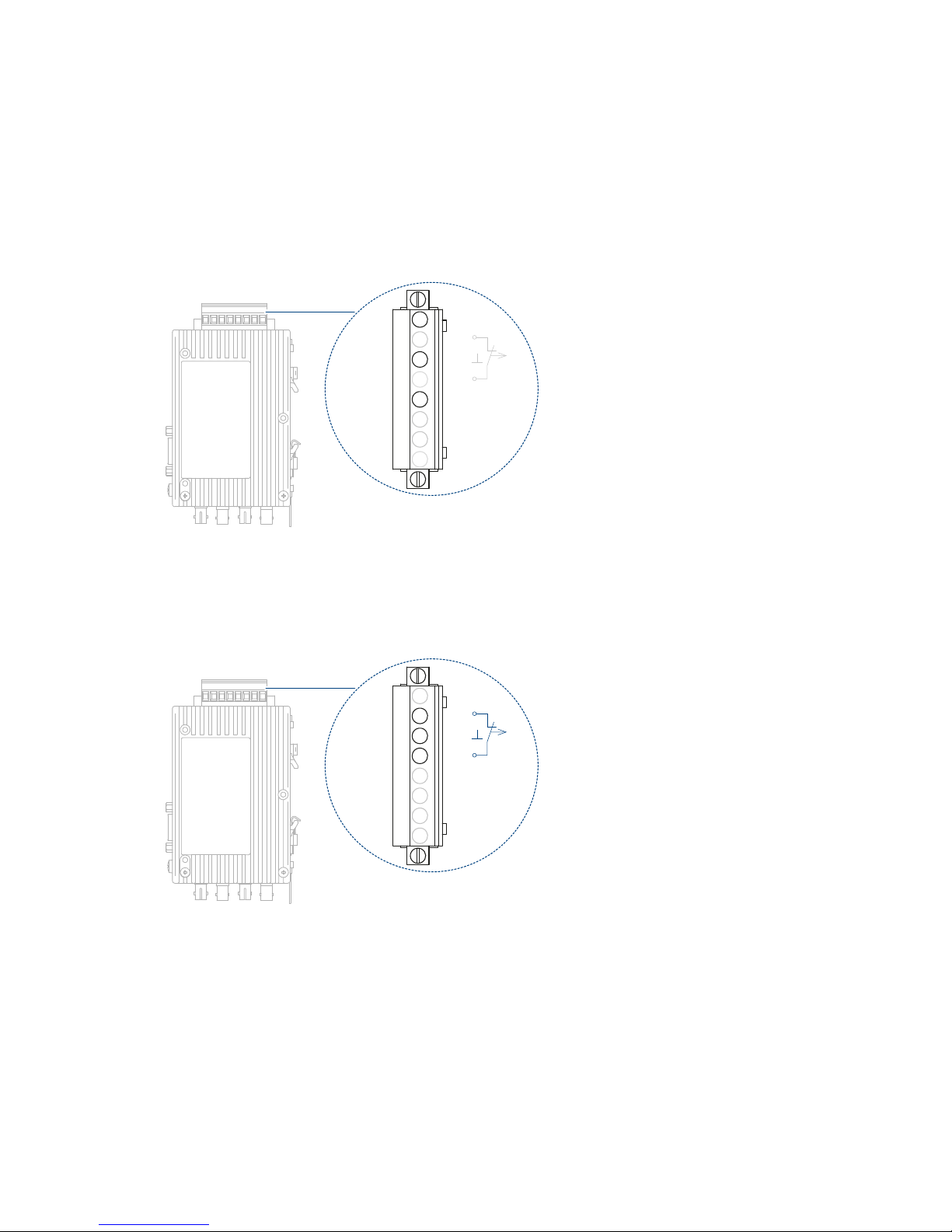
Power supply
The power supply is 24 V direct current. To improve the operating safety,
a redundant operating power supply consisting of two separate sources
can be used. For this purpose, you must connect the two supply voltages
to two different terminals of the 8-pin screw-type terminal block.Both
connections are uncoupled by means of diodes to prevent reverse voltage
supply or destruction through incorrect pole connection. There is no load
distribution between the sources. With redundant supply, the power
supply unit with the higher output voltage must supply the repeater alone.
Signal contact
A signal contact (relay with unconnected contacts) is used to signal
various disruptions in the repeaters. The signal contact is also connected
to the 8-pin screw type terminal block.
L1+
F1
0V
F2
L2+
Ua2
GND
Ua1
+24V
Fault
+24V
L1+
F1
0V
F2
L2+
Ua2
GND
Ua1
+24V
Fault
+24V
14
Installation OZD Profi 12M ...
Release 01 07/2017
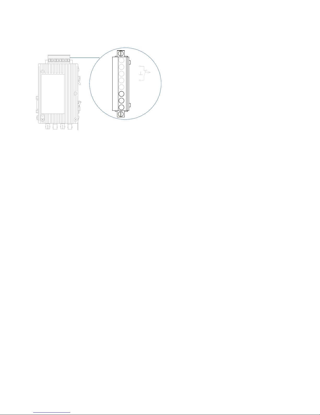
Measuring output
One measuring output is available for each optical port. The measuring
output is connected to the 8-pin screw type terminal block.
Configuration
You can easily set the configuration to meet your specific requirements by
means of DIP switches, which can easily be operated from outside.
The following settings are possible:
Setting the compatibility to OZD Profi …a version
See “Setting compatibility” on page 40.
Setting the operating mode and transmitting power
See “Setting the operating mode and transmitting power” on page 43.
Reducing the optical transmitting power
See “Reducing the optical transmitting power” on page 45.
L1+
F1
0V
F2
L2+
Ua2
GND
Ua1
+24V
Fault
+24V

Installation OZD Profi 12M ...
Release 01 07/2017
15
1.1 Non operating mode related functions
Transmission rate
The OZD Profi 12M ... support all the transmission rates defined in the EN
50170 standard:
9.6 kBit/s, 19.2 kBit/s, 45.45 kBit/s, 93.75 kBit/s,187.5 kBit/s and
500 kBit/s and additionally 1.5 MBit/s, 3 MBit/s, 6 MBit/s and 12 MBit/s.
The transmission rate is set automatically as soon as the OZD Profi 12M
... receives a frame. The setting or adjustment is dependent on the
transmission rate and the set operating mode. Depending on the OZD
Profi 12M ... this can last up to several seconds.
If the transmission speed has not been recognized, the outputs of all ports
are blocked. If the transmission rate changes during operation, this is
detected by the repeaters, which then automatically adjust their settings
accordingly.
Transfer malfunctions may temporarily occur while the rate is being
altered.
Signal regeneration
The repeaters regenerate the signal form and amplitude of the data
received. This allows up to 122 OZD Profi 12M ... to be cascaded (limited
by the address space in PROFIBUS networks).
Help when setting up
At least one bus subscriber must be switched on and active in order to
check the optical fiber connections during the installation. This bus
subscriber serves as the frame source. The OZD Profi 12M ... act
passively when it is switched on. They recognize the transfer rate from the
frames sent by the bus subscriber. An optical help when putting the
device into operation is provided by the port LED which then lights up.

16
Installation OZD Profi 12M ...
Release 01 07/2017
1.2 Operating mode related functions
The operating mode is set using switches located on the front of the repeater.
A sticker attached to the side of the repeater provides assistance with the
settings. The OZD Profi 12M ... must be switched off when switching over
DIP switches.
1.2.1 Segment monitoring at the RS 485 port
If the operating mode ”Electric channel with segment monitoring“ is set, each
receiver monitors the RS 485 bus segment connected to it for faulty frames
or continuously busy networks. If faulty frames are received by the receiver,
or if the network is busy for longer than the maximum permitted send time,
forwarding of the received signals is blocked until frames can be received
again correctly, or if no signal is received for one second.
The RS 485 bus segment is not monitored in the operating mode ”Electric
port without segment monitoring“. Interference from the electrical segment
affects the entire network.
The following functions are only available for the optical channels. Whether
the functions can be activated depends on the operating mode which has
been set.
Line monitoring with echoes
The repeaters enable the connected optical paths to be actively
monitored for interruptions in the fiber line by means of the functions
”Send echo“, ”Monitor echo“ and ”Suppress echo“.
Send echo
A frame which is received by a repeater via any port is transmitted to all
other ports. If the receiving port is an optical port, the repeater sends the
frame back to the corresponding optical sender.
Monitor echo
If a repeater sends a frame - no echo – to an optical port, the repeater
expects to receive an echo. If the echo is not received after a predefined
time, an echo monitoring error is indicated by a red LED belonging to the
port.
Suppress echo
The relevant receiver is separated from the other ports from the moment
a frame is sent until the echo has been received correctly.

Installation OZD Profi 12M ...
Release 01 07/2017
17
Segmentation
If an echo monitoring error or a frame falsification arises at an optical port,
the repeater assumes that the line is faulty and blocks this port for user
data. The connected field bus partial network is then segmented (cut off).
This segmentation causes the repeater at the other end of the optical fiber
to be segmented as well. Both repeaters connected to the segmented
field bus partial network send test frames to the segmented ports. These
test frames – which are to be received regularly – can be used by both
repeaters to check the status of the field bus partial network. The
segmentation is automatically lifted as soon as the test frames indicate to
both repeaters that the segmented field bus partial network is no longer
disturbed. If all active bus subscribers are deactivated in a previously
active network, the repeaters are segmented cyclically in order to check
the fiber links to the neighboring repeaters. If there is no frame traffic, but
the fiber links are intact, the port LEDs of the optical ports flash yellow
cyclically.
18
Installation OZD Profi 12M ...
Release 01 07/2017
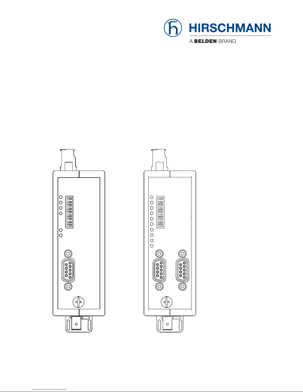
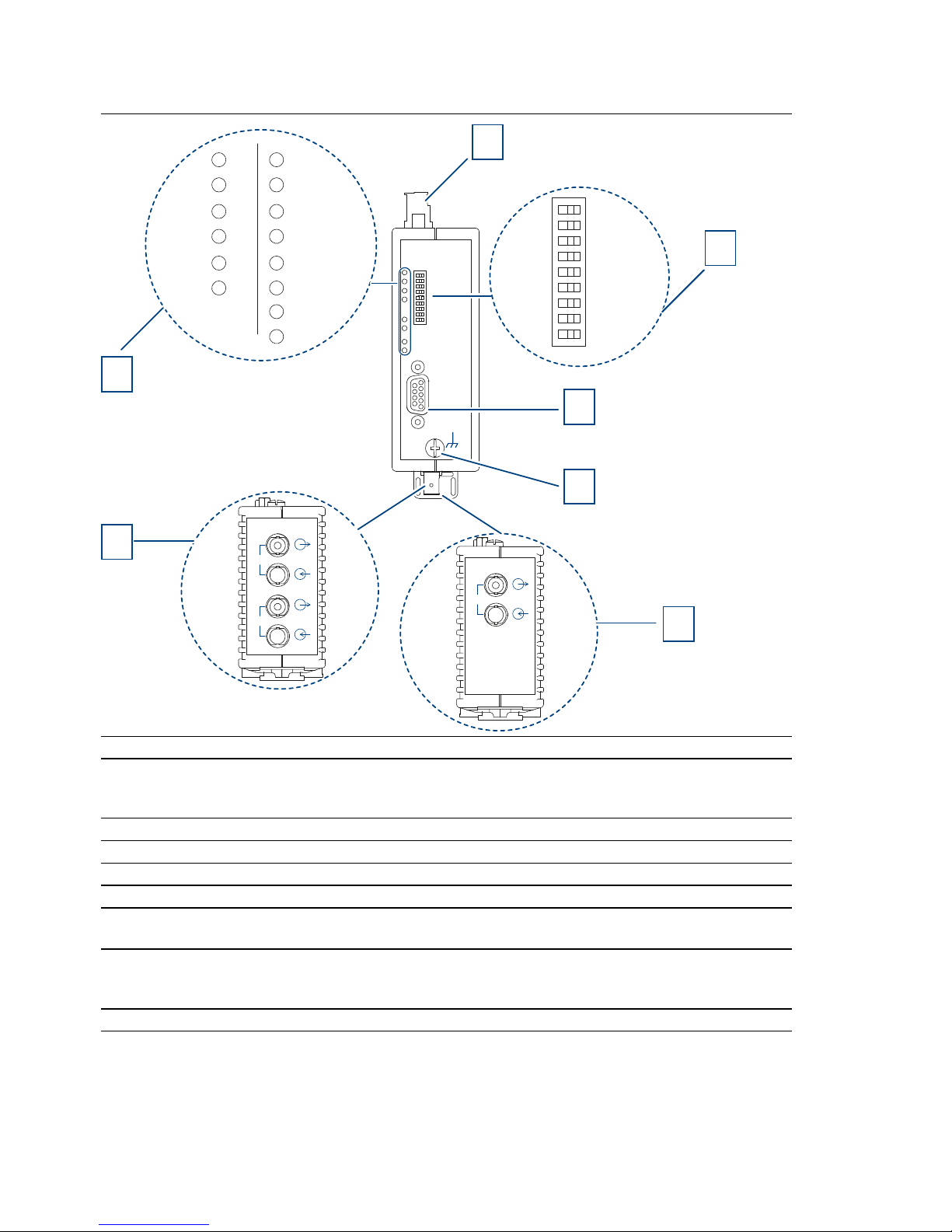
1.3 Device views
Front view using example of device variants OZD Profi 12M ...
– G11/G11-1300
– G12/G12-1300/G12-EEC/G12-1300-EEC
– P11/P12
1 8-pin terminal block for power supply, signal contact, measuring output
2 8-pin DIP switch
3 CH1 - electrical port
4 Grounding screw
5 CH3 - optical port
(only applies to the device variants OZD Profi 12M ... G11, G11-1300, P11)
6 CH3, CH4 - optical ports
(only applies to the device variants OZD Profi 12M ... G12, G12-1300, G12 EEC,G121300 EEC, P12)
7 LED display element for system status and port status
CH1
S0
S1
S2
S3
S4
S5
S6
S7
S8
1 0
System
CH1
CH3CH4
System
CH1
CH3
1
CH3
2
3
4
5
7
CH3
CH4
6
Installation OZD Profi 12M ...
Release 01 07/2017
19
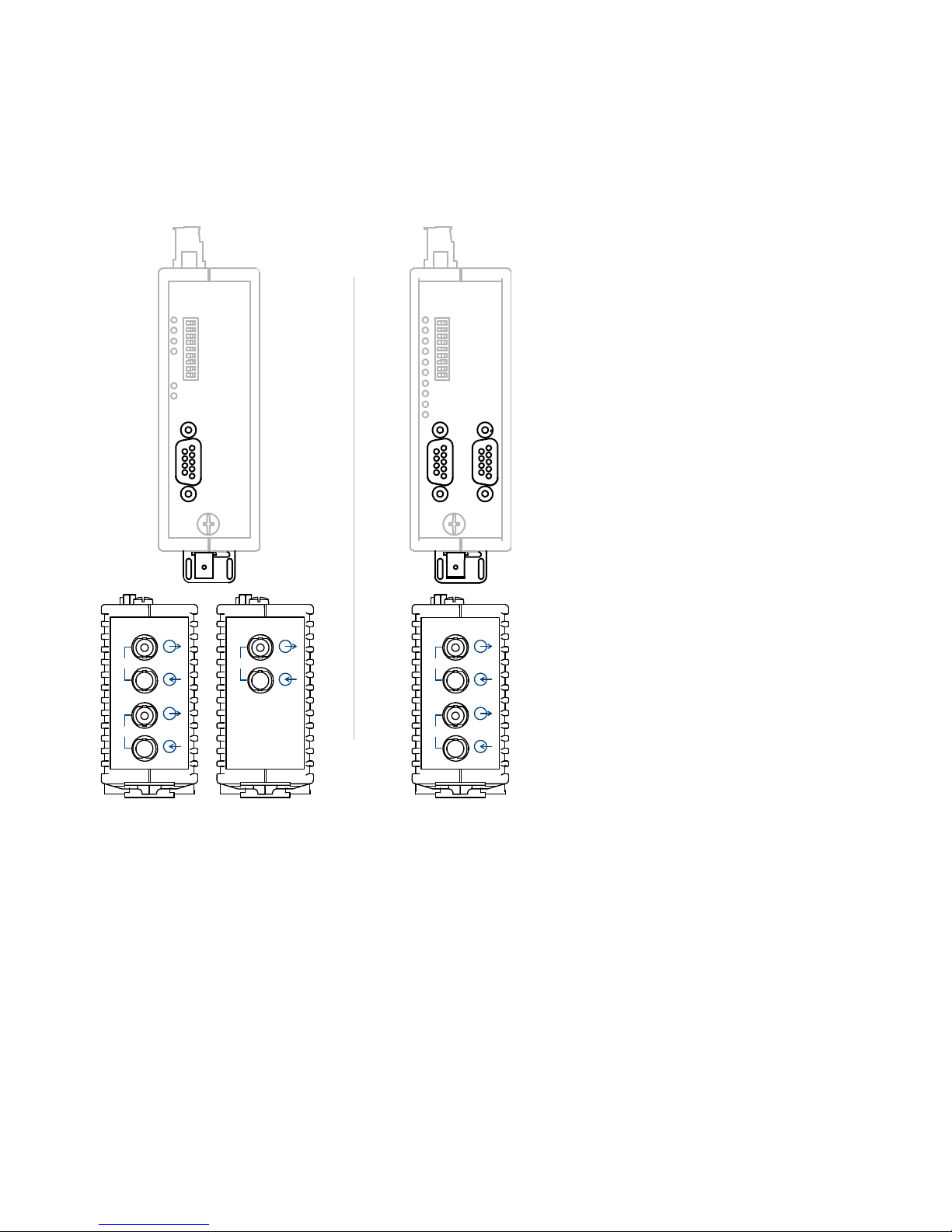
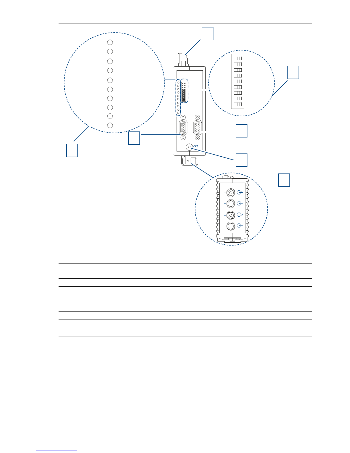
Front view using example of device variants OZD Profi 12M ...
– G22/G22-1300/G22-EEC/G22-1300-EEC
– P22
1 8-pin terminal block for power supply, signal contact, measuring output
2 8-pin DIP switch
3 CH2 - electrical port
4 Grounding screw
5 CH3, CH4 - optical ports
6 CH1 - electrical port
7 LED display element for system status and port status
CH1
CH2
CH3
CH4
S0
S1
S2
S3
S4
S5
S6
S7
S8
1 0
2
3
6
4
5
1
System
CH1CH2CH3CH4
7
20
Installation OZD Profi 12M ...
Release 01 07/2017
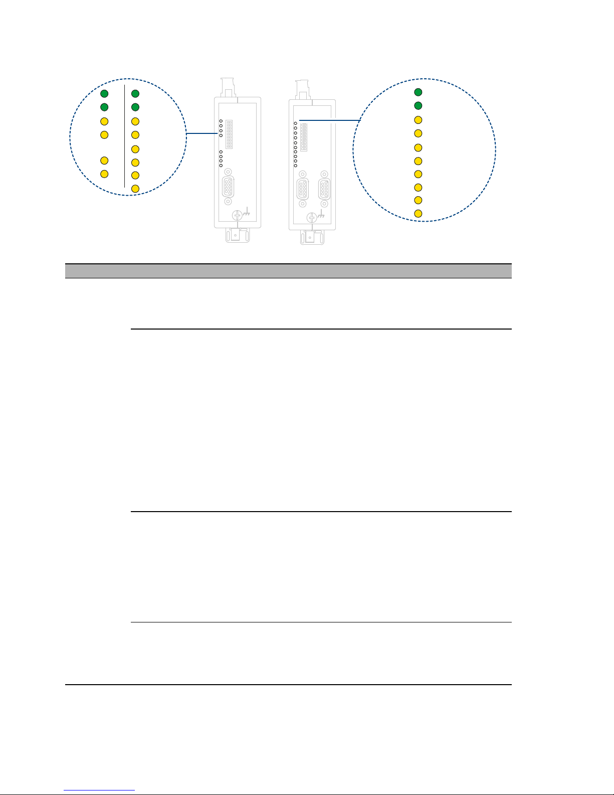
1.4 Display elements
LED Color Meaning
System green lights up The transmission rate has been recognized and the
power supply is in order
Signal contact: no signal
red flashes Transmission rate has not yet been recognized
– No transmitting bus subscriber present
– No connection to a partner repeater sending frames
– Send and receive optical fibers have been
transposed.
– Transmission rate does not correspond to
PROFIBUS-DP.
– Only one active bus subscriber is connected, which
is only sending tokens to itself. The indicator must
switch over after a second bus subscriber has been
activated (token frames on their own are not enough
to set the transfer rate).
– The connected RS 485 segment is only terminated
at one end.
Signal contact: no signal
red/green flashes Transmission rate recognized but
– the network slot time could not be determined
(network parameter HSA is set too low, no
transmitting bus subscriber present)
– one optical port is set to ”Redundant optical ring“
mode, but not the second (this operating mode must
always be set at both optical ports)
– the slot time of the network configuration is too short
Signal contact: no signal
none – Power supply has failed (total failure). Failure of
both power supply sources with redundant infeed.
– Power supply connected incorrectly
– Repeater defective
Signal contact: signal
CH1
CH1
CH2
CH4
System
CH1
CH3
System
CH1
CH3
System
CH1CH2CH3CH4

Installation OZD Profi 12M ...
Release 01 07/2017
21
electrical
ports
yellow lights up Signals are being received on the RS 485 bus line.
Signal contact: no signal
red flashes/light
s up
Sporadic interference signals because
– the RS 485 bus line being insufficiently shielded
– an open RS 485 bus line, i.e. it is only connected to
the repeater at one end
– the RS 485 segment is not terminated or only
terminated at one end
– an RS 485 bus terminal or terminal connector has
been plugged in/ pulled out
Signal contact: signal
Permanent interference because
– conductors A and B in the RS 485 bus line have
been transposed
– of an RS 485 bus line short circuit
– the send time has been exceeded caused by a bus
subscriber in a bus segment connected to Port 1
(CH1)
Signal contact: signal
– repeater and another bus subscriber connected via
Port 1 (CH1) are both sending at the same time (e.g.
because an address has been assigned twice, the
setting of the slot time is too low, or during lifting of
the segmentation in the optical lin).
Signal contact: no signal
– RS 485 driver of the repeater is defective (e.g. after
lightning strike)
none – Bus subscriber is not connected
– Connected bus subscriber is not switched on
– One or both conductors in the RS 485 bus line is
broken
Signal contact: no signal
Operating mode ”Line with optical fiber link monitoring“ and ”Redundant optical ring“
optical ports yellow lights up PROFIBUS frames are being received at the optical port
Signal contact: no signal
flashes Transmission rate has been recognized – LED ”System“
lights green or flashes red/green.
– No transmitting bus subscriber present (optical fiber
connection is OK)
Signal contact: no signal
LED Color Meaning

22
Installation OZD Profi 12M ...
Release 01 07/2017
red lights up – Send and receive optical fibers have been
transposed.
– No partner repeater connected or partner repeater
is not switched on.
– Connected partner repeater is defective
– Send time of connected partner repeater has been
exceeded
– An optical fiber line is broken
– Optical fiber link to partner repeater is too long
– Loose connection in an optical fiber connector
– Optical fiber in the optical fiber connector is loose.
– When using a redundant optical ring: if a fault in the
optical fiber has been corrected but the port LEDs
on both of the OZD Profi concerned still light red,
check whether parameter HSA has been set as
described in the chapter "Redundant Ring".
– Send and receive optical fibers have been
transposed.
Signal contact: open
red/yellow flashes – Fault occurs periodically (see above)
– Loose connection in an optical fiber connector
– Optical fiber in the optical fiber connector is loose
– Only one active bus subscriber is connected, which
only sends tokens to itself. A fault should not be
signaled as soon as a second subscriber is
activated.
Signal contact: signal
none Transmission rate has not yet been recognized – LED
”System“ flashes red
– No transmitting bus subscriber present
– Send and receive optical fibers have been
transposed
– No partner repeater connected or partner repeater
is not switched on
– Connected partner repeater is defective
Transmission rate has been recognized - LED ”System“
flashes green
– If the operating mode ”Redundant optical ring“ has
been set, the optical port works as a stand-by port.
There is no malfunction in the OZD Profi 12M ... or
the optical fiber.
– If one of the operating modes ”Line with optical fiber
link monitoring …“ has been set, no PROFIBUS
frames are received at the optical port. There is no
malfunction in the OZD Profi 12M ... or the optical
fiber.
Signal contact: no signal
Operating mode ”Line without optical fiber link monitoring“
LED Color Meaning
 Loading...