

Hirschmann OZD Profi 12M series, OZD Profi 12M G12, OZD Profi 12M G22, OZD Profi 12M G12-1300, OZD Profi 12M P12 User Manual
...
Installation OZD Profi 12M ...
Release 01 07/2017
Technical Support
https://hirschmann-support.belden.eu.com
User Manual
Installation
Fiberoptic Repeater
OZD Profi 12M ...

The naming of copyrighted trademarks in this manual, even when not specially indicated, should
not be taken to mean that these names may be considered as free in the sense of the trademark
and tradename protection law and hence that they may be freely used by anyone.
© 2017 Hirschmann Automation and Control GmbH
Manuals and software are protected by copyright. All rights reserved. The copying, reproduction,
translation, conversion into any electronic medium or machine scannable form is not permitted,
either in whole or in part. An exception is the preparation of a backup copy of the software for
your own use.
The performance features described here are binding only if they have been expressly agreed
when the contract was made. This document was produced by Hirschmann Automation and
Control GmbH according to the best of the company's knowledge. Hirschmann reserves the right
to change the contents of this document without prior notice. Hirschmann can give no guarantee
in respect of the correctness or accuracy of the information in this document.
Hirschmann can accept no responsibility for damages, resulting from the use of the network
components or the associated operating software. In addition, we refer to the conditions of use
specified in the license contract.
You can get the latest version of this manual on the Internet at the Hirschmann product site
(www.hirschmann.com).
Hirschmann Automation and Control GmbH
Stuttgarter Str. 45-51
72654 Neckartenzlingen
Germany
OZD Profi 12M ...

Installation OZD Profi 12M ...
Release 01 07/2017
3
Contents
Safety instructions 5
About this manual 10
Key 10
1 Description 11
1.1 Non operating mode related functions 15
1.2 Operating mode related functions 16
1.2.1 Segment monitoring at the RS 485 port 16
1.3 Device views 18
1.4 Display elements 20
2 Network Topologies 24
2.1 Line topology 25
2.1.1 Line topology with optical fiber link monitoring and
segmentation 26
2.1.2 Line topology without optical fiber link monitoring 27
2.2 Star topology 28
2.3 Redundant ring 30
3 Installation guidelines 32
3.1 Electromagnetic compatibility (EMC) 32
3.2 Interference suppression of switched inductances 32
3.2.1 Suppressing switched inductances with fuses 32
3.2.2 Cabinet lighting 32
3.3 Arrangement of devices and cables 33
3.3.1 Reducing interference by providing adequate space: 33
3.3.2 Standard recommendations for the arrangement of
devices and cables 33
3.3.3 Using bus line shields 33
3.3.4 Shield connections 34
3.4 Laying cables inside of buildings 35
3.5 Laying cables outside of buildings 37
4 Installation 38
4.1 Checking the package contents 38

4
Installation OZD Profi 12M ...
Release 01 07/2017
4.2 Mounting the device 39
4.2.1 Installing the device onto the DIN rail 39
4.3 Setting compatibility 40
4.4 Setting the operating mode and transmitting power 43
4.4.1 Setting the operating mode of the electrical ports
(CH1, CH2) 43
4.4.2 Setting the operating mode of the optical ports (CH3,
CH4) 44
4.4.3 Reducing the optical transmitting power 45
4.5 Connecting the optic bus cables 46
4.6 Connecting the electric bus cables 47
4.7 Connecting the function ground and the shield of the bus
cable 49
4.8 Connecting the power supply 50
4.9 Connecting the signal contact (optional) 51
4.10 Connecting the analog voltage outputs (optional) 52
5 Configuration 54
6Disassembly 56
7 Technical data 57
8 Scope of delivery, order numbers and
accessories 61
9 Underlying technical standards 62
10 Help with problems 63
10.1 Troubleshooting 63
10.2 Systematic troubleshooting 64
10.3 Problem reporting 65
A Further support 66

Installation OZD Profi 12M ...
Release 01 07/2017
5
Safety instructions
General safety instructions
You operate this device with electricity. Improper usage of the device
entails the risk of physical injury or significant property damage. The
proper and safe operation of this device depends on proper handling
during transportation, proper storage and installation, and careful
operation and maintenance procedures.
Before connecting any cable, read this document, and the safety
instructions and warnings.
Operate the device with undamaged components exclusively.
The device is free of any service components. In case of a damaged
or malfunctioning the device, turn off the supply voltage and return the
device to Hirschmann for inspection.
Qualification requirements for personnel
Only allow qualified personnel to work on the device.
Qualified personnel have the following characteristics:
Qualified personnel are properly trained. Training as well as practical
knowledge and experience make up their qualifications. This is the
prerequisite for grounding and labeling circuits, devices, and systems
in accordance with current standards in safety technology.
Qualified personnel are aware of the dangers that exist in their work.
Qualified personnel are familiar with appropriate measures against
these hazards in order to reduce the risk for themselves and others.
Qualified personnel receive training on a regular basis.
WARNING
UNCONTROLLED MACHINE ACTIONS
To avoid uncontrolled machine actions caused by data loss, configure all
the data transmission devices individually.
Before you start any machine which is controlled via data transmission, be
sure to complete the configuration of all data transmission devices.
Failure to follow these instructions can result in death, serious injury,
or equipment damage.

6
Installation OZD Profi 12M ...
Release 01 07/2017
Certified usage
Use the product only for the application cases described in the
Hirschmann product information, including this manual.
Operate the product only according to the technical specifications.
See “Technical data” on page 57.
Connect to the product only components suitable for the requirements
of the specific application case.
Device casing
Only technicians authorized by the manufacturer are permitted to open
the housing.
National and international safety regulations
Verify that the electrical installation meets local or nationally applicable
safety regulations.
Grounding the device
Functional grounding the device is by means of a separate connection on
the device.
Ground the device before connecting any other cables.
Disconnect the grounding only after disconnecting all other cables.
Ground the device via the ground screw.
Requirements for connecting electrical wires
Before connecting the electrical wires, always verify that the
requirements listed are complied with.
All of the following requirements are complied with:
The electrical wires are voltage-free.
The cables used are permitted for the temperature range of the application case.
Table 1: General requirements for connecting electrical wires
All of the following requirements are complied with:
The voltage connected complies with the requirements for a safety extra-low voltage
(SELV) as per IEC/EN 60950-1.
The connected voltage is limited by a current limitation device or a fuse.
Observe the electrical threshold values for the signal contact.
See “General technical data” on page 57.
Table 2: Requirements for connecting the signal contact

Installation OZD Profi 12M ...
Release 01 07/2017
7
Supply voltage
Only switch on the device when the housing is closed.
Requirements
All of the following requirements are complied with:
The supply voltage corresponds to the voltage specified on the type plate of the device.
The power supply conforms to overvoltage category I or II.
The power supply has an easily accessible disconnecting device (e.g., a switch or a plug).
This disconnecting device is clearly identified. So in the case of an emergency, it is clear
which disconnecting device belongs to which power supply cable.
The cross-section of the ground conductor is the same size as or bigger than the cross-
section of the power supply cables.
Relevant for North America:
The power cords are suitable for ambient air temperatures of at least 167 °F (75 °C). The
power cord wires are made of copper.
The wire diameter of the power supply cable is at least 0.75 mm² (North America: AWG18) on
the supply voltage input.
The following requirements are alternatively complied with:
Alternative 1 The power supply complies with the requirements for a limited
power source (LPS) as per EN 60950-1.
Alternative 2 Relevant for North America:
The power supply complies with the requirements as per Class 2
Alternative 3 All of the following requirements are complied with:
The power supply complies with the requirements for a safety
extra-low voltage (SELV) as per IEC/EN 60950-1.
A fuse suitable for DC voltage is located in the plus conductor
of the power supply.
The minus conductor is on ground potential. Otherwise, a fuse
is also located in the minus conductor.
Regarding the properties of this fuse:
See “General technical data” on page 57.
Table 3: Requirements for connecting the supply voltage

8
Installation OZD Profi 12M ...
Release 01 07/2017
CE marking
The labeled devices comply with the regulations contained in the following
European directive(s):
2014/30/EU (EMC)
Directive of the European Parliament and the council for standardizing the
regulations of member states with regard to electromagnetic
compatibility.
2011/65/EU (RoHS)
Directive of the European Parliament and of the Council on the restriction
of the use of certain hazardous substances in electrical and electronic
equipment.
In accordance with the above-named EU directive(s), the EU conformity
declaration will be at the disposal of the relevant authorities at the
following address:
Hirschmann Automation and Control GmbH
Stuttgarter Str. 45-51
72654 Neckartenzlingen
Germany
The product can be used in the industrial sector.
Interference immunity: EN 61000-6-2
Emitted interference: EN 55032
Reliability: EN 60950-1
You find more information on technical standards here:
“Technical data” on page 57
Warning! This is a class A device. This device can cause interference in
living areas, and in this case the operator may be required to take
appropriate measures.
Note: The assembly guidelines provided in these instructions must be
strictly adhered to in order to observe the EMC threshold values.
LED or laser components
LED or LASER components according to IEC 60825-1 (2014):
CLASS 1 LASER PRODUCT
CLASS 1 LED PRODUCT

Installation OZD Profi 12M ...
Release 01 07/2017
9
FCC note:
This device complies with part 15 of the FCC rules. Operation is subject
to the following two conditions: (1) this device may not cause harmful
interference; (2) this device must accept any interference received,
including interference that may cause undesired operation.
Appropriate testing has established that this device fulfills the
requirements of a class A digital device in line with part 15 of the FCC
regulations.
These requirements are designed to provide sufficient protection against
interference when the device is being used in a business environment.
The device creates and uses high frequencies and can also radiate these
frequencies. If it is not installed and used in accordance with this
operating manual, it can cause radio transmission interference. The use
of this device in a residential area can also cause interference, and in this
case the user is obliged to cover the costs of removing the interference.
Recycling note
After usage, this device must be disposed of properly as electronic waste,
in accordance with the current disposal regulations of your county, state,
and country.

10
Installation OZD Profi 12M ...
Release 01 07/2017
About this manual
The “Installation” user manual contains a device description, safety
instructions, a description of the display, and the other information that you
need to install the device.
Key
The symbols used in this manual have the following meanings:
Listing
Work step
Subheading

Installation OZD Profi 12M ...
Release 01 07/2017
11
1 Description
The PROFIBUS Repeaters are designed to be used in optical PROFIBUS
field bus networks according to IEC 61784. They enable electrical
PROFIBUS interfaces (RS 485 level) to be converted into optical PROFIBUS
interfaces and vice-versa. By profiting from the familiar advantages of optical
transmission technology, the repeaters can be integrated into existing
PROFIBUS field bus networks. A complete PROFIBUS field bus network
with repeaters in line, star or ring topology, and an arbitrary combination of
these, can also be built up.
Device casing
The device is supplied in a metal housing. You have the option of
mounting the device onto the DIN rail.
Glass fiber technology
The use of glass fiber transmission technology enables a very large
transmission range and ensures optimal protection from EMC effects on
the transmission path and – due to the potential separation – on the
Repeater itself.
Transmission rate
The OZD Profi 12M ... supports data rates from 9.6 kBit/s to 12 Mbit/s.
Redundancy
The redundant ring enables a very high level of transmission reliability.
The redundant operating power supply can further improve the operating
reliability.
12
Installation OZD Profi 12M ...
Release 01 07/2017
Port
Depending on a device variant, each device has 2,3,4 mutually
independent ports (channels), which in turn consist of a transmitting and
a receiving component. The electric ports are a 9-pole D-Sub socket
(female). A PROFIBUS bus segment can be connected to this ports. The
optical ports are BFOC/2.5 (ST ®) sockets.
CH3
CH4
CH3 CH3
CH4
CH1
CH1
CH2
Installation OZD Profi 12M ...
Release 01 07/2017
13
Power supply
The power supply is 24 V direct current. To improve the operating safety,
a redundant operating power supply consisting of two separate sources
can be used. For this purpose, you must connect the two supply voltages
to two different terminals of the 8-pin screw-type terminal block.Both
connections are uncoupled by means of diodes to prevent reverse voltage
supply or destruction through incorrect pole connection. There is no load
distribution between the sources. With redundant supply, the power
supply unit with the higher output voltage must supply the repeater alone.
Signal contact
A signal contact (relay with unconnected contacts) is used to signal
various disruptions in the repeaters. The signal contact is also connected
to the 8-pin screw type terminal block.
L1+
F1
0V
F2
L2+
Ua2
GND
Ua1
+24V
Fault
+24V
L1+
F1
0V
F2
L2+
Ua2
GND
Ua1
+24V
Fault
+24V
14
Installation OZD Profi 12M ...
Release 01 07/2017
Measuring output
One measuring output is available for each optical port. The measuring
output is connected to the 8-pin screw type terminal block.
Configuration
You can easily set the configuration to meet your specific requirements by
means of DIP switches, which can easily be operated from outside.
The following settings are possible:
Setting the compatibility to OZD Profi …a version
See “Setting compatibility” on page 40.
Setting the operating mode and transmitting power
See “Setting the operating mode and transmitting power” on page 43.
Reducing the optical transmitting power
See “Reducing the optical transmitting power” on page 45.
L1+
F1
0V
F2
L2+
Ua2
GND
Ua1
+24V
Fault
+24V

Installation OZD Profi 12M ...
Release 01 07/2017
15
1.1 Non operating mode related functions
Transmission rate
The OZD Profi 12M ... support all the transmission rates defined in the EN
50170 standard:
9.6 kBit/s, 19.2 kBit/s, 45.45 kBit/s, 93.75 kBit/s,187.5 kBit/s and
500 kBit/s and additionally 1.5 MBit/s, 3 MBit/s, 6 MBit/s and 12 MBit/s.
The transmission rate is set automatically as soon as the OZD Profi 12M
... receives a frame. The setting or adjustment is dependent on the
transmission rate and the set operating mode. Depending on the OZD
Profi 12M ... this can last up to several seconds.
If the transmission speed has not been recognized, the outputs of all ports
are blocked. If the transmission rate changes during operation, this is
detected by the repeaters, which then automatically adjust their settings
accordingly.
Transfer malfunctions may temporarily occur while the rate is being
altered.
Signal regeneration
The repeaters regenerate the signal form and amplitude of the data
received. This allows up to 122 OZD Profi 12M ... to be cascaded (limited
by the address space in PROFIBUS networks).
Help when setting up
At least one bus subscriber must be switched on and active in order to
check the optical fiber connections during the installation. This bus
subscriber serves as the frame source. The OZD Profi 12M ... act
passively when it is switched on. They recognize the transfer rate from the
frames sent by the bus subscriber. An optical help when putting the
device into operation is provided by the port LED which then lights up.

16
Installation OZD Profi 12M ...
Release 01 07/2017
1.2 Operating mode related functions
The operating mode is set using switches located on the front of the repeater.
A sticker attached to the side of the repeater provides assistance with the
settings. The OZD Profi 12M ... must be switched off when switching over
DIP switches.
1.2.1 Segment monitoring at the RS 485 port
If the operating mode ”Electric channel with segment monitoring“ is set, each
receiver monitors the RS 485 bus segment connected to it for faulty frames
or continuously busy networks. If faulty frames are received by the receiver,
or if the network is busy for longer than the maximum permitted send time,
forwarding of the received signals is blocked until frames can be received
again correctly, or if no signal is received for one second.
The RS 485 bus segment is not monitored in the operating mode ”Electric
port without segment monitoring“. Interference from the electrical segment
affects the entire network.
The following functions are only available for the optical channels. Whether
the functions can be activated depends on the operating mode which has
been set.
Line monitoring with echoes
The repeaters enable the connected optical paths to be actively
monitored for interruptions in the fiber line by means of the functions
”Send echo“, ”Monitor echo“ and ”Suppress echo“.
Send echo
A frame which is received by a repeater via any port is transmitted to all
other ports. If the receiving port is an optical port, the repeater sends the
frame back to the corresponding optical sender.
Monitor echo
If a repeater sends a frame - no echo – to an optical port, the repeater
expects to receive an echo. If the echo is not received after a predefined
time, an echo monitoring error is indicated by a red LED belonging to the
port.
Suppress echo
The relevant receiver is separated from the other ports from the moment
a frame is sent until the echo has been received correctly.

Installation OZD Profi 12M ...
Release 01 07/2017
17
Segmentation
If an echo monitoring error or a frame falsification arises at an optical port,
the repeater assumes that the line is faulty and blocks this port for user
data. The connected field bus partial network is then segmented (cut off).
This segmentation causes the repeater at the other end of the optical fiber
to be segmented as well. Both repeaters connected to the segmented
field bus partial network send test frames to the segmented ports. These
test frames – which are to be received regularly – can be used by both
repeaters to check the status of the field bus partial network. The
segmentation is automatically lifted as soon as the test frames indicate to
both repeaters that the segmented field bus partial network is no longer
disturbed. If all active bus subscribers are deactivated in a previously
active network, the repeaters are segmented cyclically in order to check
the fiber links to the neighboring repeaters. If there is no frame traffic, but
the fiber links are intact, the port LEDs of the optical ports flash yellow
cyclically.
18
Installation OZD Profi 12M ...
Release 01 07/2017
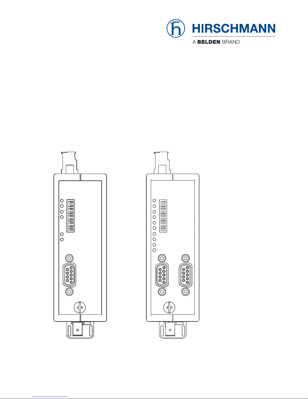
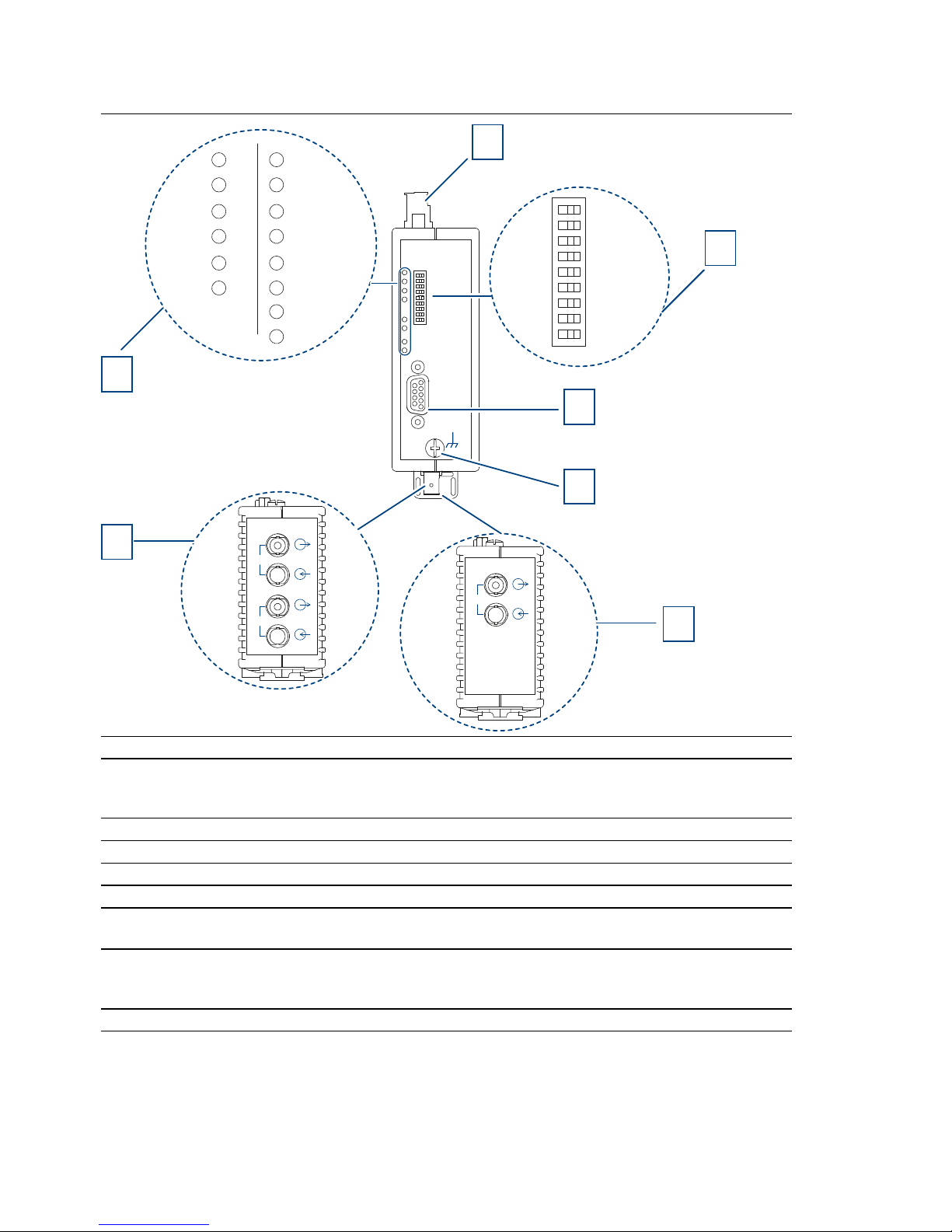
1.3 Device views
Front view using example of device variants OZD Profi 12M ...
– G11/G11-1300
– G12/G12-1300/G12-EEC/G12-1300-EEC
– P11/P12
1 8-pin terminal block for power supply, signal contact, measuring output
2 8-pin DIP switch
3 CH1 - electrical port
4 Grounding screw
5 CH3 - optical port
(only applies to the device variants OZD Profi 12M ... G11, G11-1300, P11)
6 CH3, CH4 - optical ports
(only applies to the device variants OZD Profi 12M ... G12, G12-1300, G12 EEC,G121300 EEC, P12)
7 LED display element for system status and port status
CH1
S0
S1
S2
S3
S4
S5
S6
S7
S8
1 0
System
CH1
CH3CH4
System
CH1
CH3
1
CH3
2
3
4
5
7
CH3
CH4
6
Installation OZD Profi 12M ...
Release 01 07/2017
19
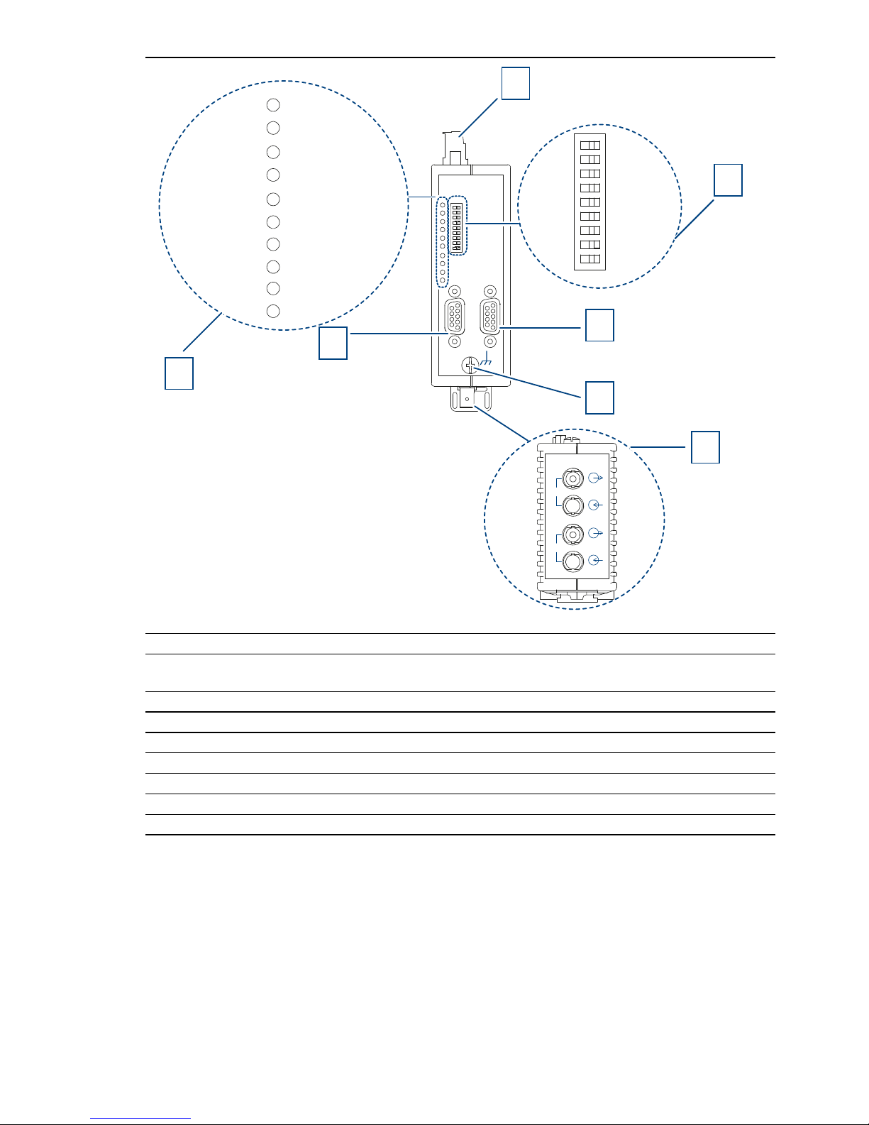
Front view using example of device variants OZD Profi 12M ...
– G22/G22-1300/G22-EEC/G22-1300-EEC
– P22
1 8-pin terminal block for power supply, signal contact, measuring output
2 8-pin DIP switch
3 CH2 - electrical port
4 Grounding screw
5 CH3, CH4 - optical ports
6 CH1 - electrical port
7 LED display element for system status and port status
CH1
CH2
CH3
CH4
S0
S1
S2
S3
S4
S5
S6
S7
S8
1 0
2
3
6
4
5
1
System
CH1CH2CH3CH4
7
20
Installation OZD Profi 12M ...
Release 01 07/2017
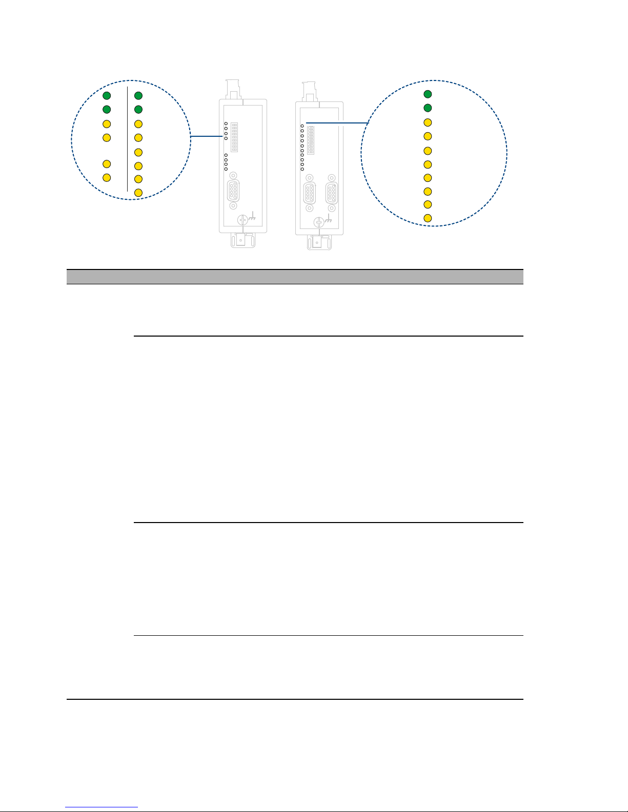
1.4 Display elements
LED Color Meaning
System green lights up The transmission rate has been recognized and the
power supply is in order
Signal contact: no signal
red flashes Transmission rate has not yet been recognized
– No transmitting bus subscriber present
– No connection to a partner repeater sending frames
– Send and receive optical fibers have been
transposed.
– Transmission rate does not correspond to
PROFIBUS-DP.
– Only one active bus subscriber is connected, which
is only sending tokens to itself. The indicator must
switch over after a second bus subscriber has been
activated (token frames on their own are not enough
to set the transfer rate).
– The connected RS 485 segment is only terminated
at one end.
Signal contact: no signal
red/green flashes Transmission rate recognized but
– the network slot time could not be determined
(network parameter HSA is set too low, no
transmitting bus subscriber present)
– one optical port is set to ”Redundant optical ring“
mode, but not the second (this operating mode must
always be set at both optical ports)
– the slot time of the network configuration is too short
Signal contact: no signal
none – Power supply has failed (total failure). Failure of
both power supply sources with redundant infeed.
– Power supply connected incorrectly
– Repeater defective
Signal contact: signal
CH1
CH1
CH2
CH4
System
CH1
CH3
System
CH1
CH3
System
CH1CH2CH3CH4

Installation OZD Profi 12M ...
Release 01 07/2017
21
electrical
ports
yellow lights up Signals are being received on the RS 485 bus line.
Signal contact: no signal
red flashes/light
s up
Sporadic interference signals because
– the RS 485 bus line being insufficiently shielded
– an open RS 485 bus line, i.e. it is only connected to
the repeater at one end
– the RS 485 segment is not terminated or only
terminated at one end
– an RS 485 bus terminal or terminal connector has
been plugged in/ pulled out
Signal contact: signal
Permanent interference because
– conductors A and B in the RS 485 bus line have
been transposed
– of an RS 485 bus line short circuit
– the send time has been exceeded caused by a bus
subscriber in a bus segment connected to Port 1
(CH1)
Signal contact: signal
– repeater and another bus subscriber connected via
Port 1 (CH1) are both sending at the same time (e.g.
because an address has been assigned twice, the
setting of the slot time is too low, or during lifting of
the segmentation in the optical lin).
Signal contact: no signal
– RS 485 driver of the repeater is defective (e.g. after
lightning strike)
none – Bus subscriber is not connected
– Connected bus subscriber is not switched on
– One or both conductors in the RS 485 bus line is
broken
Signal contact: no signal
Operating mode ”Line with optical fiber link monitoring“ and ”Redundant optical ring“
optical ports yellow lights up PROFIBUS frames are being received at the optical port
Signal contact: no signal
flashes Transmission rate has been recognized – LED ”System“
lights green or flashes red/green.
– No transmitting bus subscriber present (optical fiber
connection is OK)
Signal contact: no signal
LED Color Meaning

22
Installation OZD Profi 12M ...
Release 01 07/2017
red lights up – Send and receive optical fibers have been
transposed.
– No partner repeater connected or partner repeater
is not switched on.
– Connected partner repeater is defective
– Send time of connected partner repeater has been
exceeded
– An optical fiber line is broken
– Optical fiber link to partner repeater is too long
– Loose connection in an optical fiber connector
– Optical fiber in the optical fiber connector is loose.
– When using a redundant optical ring: if a fault in the
optical fiber has been corrected but the port LEDs
on both of the OZD Profi concerned still light red,
check whether parameter HSA has been set as
described in the chapter "Redundant Ring".
– Send and receive optical fibers have been
transposed.
Signal contact: open
red/yellow flashes – Fault occurs periodically (see above)
– Loose connection in an optical fiber connector
– Optical fiber in the optical fiber connector is loose
– Only one active bus subscriber is connected, which
only sends tokens to itself. A fault should not be
signaled as soon as a second subscriber is
activated.
Signal contact: signal
none Transmission rate has not yet been recognized – LED
”System“ flashes red
– No transmitting bus subscriber present
– Send and receive optical fibers have been
transposed
– No partner repeater connected or partner repeater
is not switched on
– Connected partner repeater is defective
Transmission rate has been recognized - LED ”System“
flashes green
– If the operating mode ”Redundant optical ring“ has
been set, the optical port works as a stand-by port.
There is no malfunction in the OZD Profi 12M ... or
the optical fiber.
– If one of the operating modes ”Line with optical fiber
link monitoring …“ has been set, no PROFIBUS
frames are received at the optical port. There is no
malfunction in the OZD Profi 12M ... or the optical
fiber.
Signal contact: no signal
Operating mode ”Line without optical fiber link monitoring“
LED Color Meaning

Installation OZD Profi 12M ...
Release 01 07/2017
23
optical ports yellow lights up Signals are received at the optical channel.
Signal contact: no signal
none – No transmitting bus subscriber present
– Send and receive optical fibers have been
transposed
– No partner repeater connected or partner repeater
is not switched on
– Connected partner repeater is defective
Signal contact: no signal
LED Color Meaning

24
Installation OZD Profi 12M ...
Release 01 07/2017
2 Network Topologies
The following network topologies can be realized with the OZD Profi 12M ...:
Point-to-point connections
Line topologies
Star topologies
Redundant optical rings
Note:
Single terminals or entire PROFIBUS segments with max. 31 subscribers
can be connected to the electrical interface of the OZD Profi 12M ...
In areas with a high EMC incidence, only lay optical fiber lines in order to
exclude the possibility of EMC affecting the whole network.
Optically only OZD Profi 12M ... of the same type can be connected
together: OZD Profi 12M P11 with … P12, OZD Profi 12M G11 with
…G12 and …G12 EEC, OZD Profi 12M G11-1300 with … G12-1300 and
…G12-1300 EEC.
Optical ports which are connected by optical fiber must be set to the same
operating mode.
Junctions between different OZD Profi 12M ... types are only possible via
the RS 485 interface.
OZD Profi 12M G12 (-1300) EEC can be used everywhere in those
network topologies described below in which a OZD Profi 12M G12(-
1300) can also be used.

Installation OZD Profi 12M ...
Release 01 07/2017
25
2.1 Line topology
Figure 1: Network structure in an optical line topology
In a line structure, the individual OZD Profi 12M ... are connected together by
dual-fiber optical fibers. Repeaters with one optical port are sufficient at the
beginning and end of a line, between which repeaters with two optical ports
are necessary.
If single point-to-point connections are to be built up, this can be achieved
using two repeaters each with one optical port.
The line topology can be realized with and without fiber link monitoring. If
both operating modes are used within an optical fiber line, the operating
mode ”Line topology without fiber link monitoring“ determines the availability
of this fiber line. It is recommended that fiber link monitoring be used in
homogeneous OZD Profi networks (default factory setting).
Please note that the following ambient conditions must be fulfilled to ensure
that network configuration functions correctly:
The parameters MIN T
SDR
described in the PROFIBUS standard EN
50170 must be set to a value ≥ 11 on all terminals. This is usually the
case, but the setting should be checked if communication malfunctions
continuously arise.
When configuring your network, select low bus subscriber addresses
wherever possible. This ensures that master timeout times which may
arise are kept as short as possible in the event of a malfunction.
CH 1
CH3
Terminal unit(s) /
bus segment
OZD …
P11
G11 (-1300)
CH 1
CH3
Terminal unit(s) /
bus segment
OZD …
P11
G11 (-1300)
CH 1
Terminal unit(s) /
bus segment
OZD …
P12
G12 (-1300)
CH4CH3

26
Installation OZD Profi 12M ...
Release 01 07/2017
2.1.1 Line topology with optical fiber link monitoring and
segmentation
This operating mode should preferably be used if an interrupted fiber
segment is to be separated from the rest of the network.
In this operating mode the individual fiber links are monitored by the two
connected repeaters.
If a repeater fails, an optical fiber breaks or faults are determined on the
optical transfer link, the fiber link between the two Fiberoptic Repeater is
interrupted (segmented).
The PROFIBUS network is divided into two partial networks, which remain
functional independently of one other. The malfunction is indicated at the two
OZD Profi 12M ... that are connected to the malfunctioning fiber link by the
port LEDs switching to red and by activation of the signaling contacts. The
segmentation is lifted automatically as soon as both repeaters recognize that
the field bus network is functioning correctly with the help of test frames.
Please note that in the case of networks with several active bus subscribers,
two logical token rings are formed in the event of an error. Every time the
partial networks are switched together, network malfunctions may arise due
to the double tokens or frame collisions.
Note: If a repeater with two optical channels is used at the beginning or end
of a line, the optical port which is not assigned must be switched to the
operating mode ”Line without fiber link monitoring“, so that it does not signal
a break in the fiber line. Please note that optical ports which are not
connected must always be fitted with protective caps to guard against
extraneous light and dirt.
Monitoring mechanisms
Send echo yes
Monitor echo yes
Suppress echo yes
Monitor yes
Segmentation yes

Installation OZD Profi 12M ...
Release 01 07/2017
27
2.1.2 Line topology without optical fiber link monitoring
Use this operating mode if you connect a OZD Profi 12M ... with another
optical fiber network component, which does not send a frame echo and does
not expect or is not compatible with a frame echo in accordance with
PROFIBUS guidelines (optical/electrical converter).
Individual fiber links are not monitored in this operating mode.
Monitoring mechanism
Send echo no
Monitor echo no
Suppress echo no
Monitor no
Segmentation no

28
Installation OZD Profi 12M ...
Release 01 07/2017
2.2 Star topology
Figure 2: Network structure in an optic star topology
Several repeaters are combined to form an active PROFIBUS star coupler.
Other repeaters are connected to this by dual-fiber optical fiber lines. The
repeaters of the star coupler are connected to one another via the electrical
port (electrical star segment). All OZD Profi 12M ... types for different fiber
types (plastic, PCF, glass) can be combined using the electrical star
segment.
CH1
CH3
Terminal unit(s) /
bus segment
OZD …
P11
G11 (-1300)
CH1
CH3
Terminal unit(s) /
bus segment
OZD …
P11
G11 (-1300)
CH1
CH3
Terminal unit(s) /
bus segment
OZD …
P11
G11 (-1300)
CH1
CH3
Terminal unit(s) /
bus segment
OZD …
P11
G11 (-1300)
CH1
CH3
Terminal unit(s) /
bus segment
OZD …
P11
G11 (-1300)
CH1
CH3
OZD …
P11
G11 (-1300)
CH1
CH3
OZD …
P11
G11 (-1300)
CH1
CH3
OZD …
P11
G11 (-1300)
CH1
OZD …
P12
G12 (-1300)
CH4CH3
Electrical star segment

Installation OZD Profi 12M ...
Release 01 07/2017
29
CH1 in mode ”Monitor off“ (S0 = 1) must be activated on all OZD Profi
12M ... which are connected to the electrical star segment. This
deactivates the segmenting function of the RS 485 port on these OZD
Profi 12M ..., providing a high degree of availability of the electrical star
segment.
Ensure that the electrical star segment is wired carefully. Keep it as small
as possible to avoid interference injection into the electrical star segment,
and from here into the entire network. This can be achieved by laying out
the OZD Profi 12M ... in the electrical star segment directly next to each
other on a hat rail.
Switch on the terminating resistors in the bus port connectors at both ends
of the electrical star segment.
See “Connecting the electric bus cables” on page 47.
Do not connect a bus subscriber to the electrical star segment wherever
possible.
This applies exclusively to device variants OZD Profi 12M x22:
Connect other bus subscribers to the second electrical port (CH2).
Repeaters with one or two optical ports can be used to create an active
PROFIBUS star coupler. Repeaters with one optical port are sufficient for
connecting a terminal or an RS 485 bus segment to the active star coupler.
If the link monitoring on the optical ports is activated, the fiber optic links are
monitored by the respectively connected OZD Profi 12M ... .
Note: Optical ports which are not assigned (for instance, because they are
reserved for a future system extension) indicate a fiber break if the link
monitoring is activated. You can prevent this error report from being issued
by activating the operating mode ”Line without fiber link monitoring“ at the
non-assigned ports. Please note that optical ports which are not connected
must always be fitted with protective caps to guard against extraneous light
and dirt.

30
Installation OZD Profi 12M ...
Release 01 07/2017
2.3 Redundant ring
Figure 3: Network structure in a redundant optical ring topology
This network topology represents a special form of line topology. A high
degree of network operating safety is achieved by ”closing“ the optical line.
A redundant optical ring ca only be realized with repeaters with two optical
ports of the same fiber.
An interruption of one or both optical fibers between two repeaters is
detected by the OZD Profi 12M ... and the ring is transformed into an optical
line.
If one repeater fails only those terminals connected to this repeater or the RS
485 segment are uncoupled from the ring. The remainder of the network itself
continues to function as a line. The error is indicated by the LEDs on the two
OZD Profi 12M ... connected to the malfunctioning optical fiber and their
signaling contacts. The segmentation is lifted automatically as soon as both
repeaters recognize that the segmented field bus network is functioning
correctly with the help of test frames. The line forms itself into a ring.
Monitoring mechanism
Send echo yes
Monitor echo yes
Suppress echo yes
Monitor yes
Segmentation yes
CH1
Terminal unit(s) /
bus segment
OZD …
P12
G12 (-1300)
CH4CH3
CH1
Terminal unit(s) /
bus segment
OZD …
P12
G12 (-1300)
CH4CH3
CH1
Terminal unit(s) /
bus segment
OZD …
P12
G12 (-1300)
CH4CH3

Installation OZD Profi 12M ...
Release 01 07/2017
31
The following ambient conditions must be fulfilled to ensure that the network
configuration functions correctly:
The operating mode ”Redundant optical ring“ must be set at both optical
ports of all the OZD Profi 12M ... .
All repeaters in a ring must be connected to one another by fiber lines.
The ring may not include an RS 485 bus line.
The parameter MIN T
SDR
described in the PROFIBUS standard
EN 50170 must be set to a value ≥ 11on all terminals. This is usually the
case, but the setting should be checked if communication malfunctions
continuously arise.
When configuring your network, select low bus subscriber addresses
wherever possible. This ensures that master timeout times which may
arise are kept as short as possible in the event of a malfunction.
If a redundancy case occurs (e.g. a line break), there is a switching time
during which data can not be correctly transmitted. In order to ensure a
smooth transition, it is recommended that the frame repeat setting (Retry)
on the PROFIBUS master be set to at least 3.
After the error has been corrected, no frames should be present in the
network when the optical line is transformed back into an optical ring to
ensure that the process is completed smoothly. This condition can arise
when a master selects a device whose address has been configured, but
which does not physically exist.
The master tries to address this device cyclically and waits for a reply only
until the configured slot time has been exceeded (”GAP request“). The
OZD Profi 12M ... recognizes this condition and closes the optical line to
an optical ring in the middle of this request sequence. This results in two
configuration requirements for the redundant optical ring:
– The value of the parameter HSA (Highest Station Address) must be
set at all terminals so that between the bus address 0 and the value
HSA at least one address in the network has not been assigned to a
bus subscriber, i.e. so that there is at least one address gap. This
address gap can also be created by simply setting the value of the
parameter HSA so that it is at least one greater than the highest
number of subscriber bus addresses present in the network.
Note: If this requirement is not or no longer fulfilled, the optical line will no
longer be closed into a redundant optical ring after segmentation. The error
report (LED and signaling contact) of the two affected OZD Profi 12M ... is
not cancelled even after the error has been corrected.
– The slot time must be set to approximately twice the value required in
a non-redundant network. Refer to the manufacturer’s documentation
provided with the terminal or configuration software for details about
how to adjust the settings.

32
Installation OZD Profi 12M ...
Release 01 07/2017
3 Installation guidelines
3.1 Electromagnetic compatibility (EMC)
Electromagnetic compatibility (EMC) covers all aspects regarding the effects
of radiated and received electrical, magnetic, and electromagnetic
emissions. In order to prevent interference in electrical systems, these
effects must be reduced to a minimum. The structural design and correct
connection of bus lines as well as the interference suppression of switched
inductances play a major role in limiting interference.
3.2 Interference suppression of switched
inductances
Figure 4: Interference suppression of fluorescent lamps in cabinet
3.2.1 Suppressing switched inductances with fuses
Switching inductances, e.g. in relays and fans, generates interference
voltages which are many times higher than the switched operating voltage.
These interference voltages can affect electronic devices. The interference
voltages of inductances must be limited at their source of emission by means
of fuses (by connecting diodes or RC elements). Only use interference
suppressors which are intended for the used relays and fans.
3.2.2 Cabinet lighting
Use filament lamps (e.g. LINESTRA lamps) for the cabinet lighting.
Do not use fluorescent lamps because they generate interference fields.
If the use of fluorescent lamps cannot be avoided, the interference
suppression measures shown in Fig. 4 must be implemented.
Shield grid
over lamp
Shielded cable
Metal-encased
switch
Mains filter or
shielded mains cable

Installation OZD Profi 12M ...
Release 01 07/2017
33
3.3 Arrangement of devices and cables
3.3.1 Reducing interference by providing adequate space:
A simple yet effective way of reducing interference is to separate devices and
cables causing interference from those affected by interference. Inductive
and capacitive interference injection decreases by the square of the distance
between the elements concerned. This means that doubling the distance
reduces the interference by a factor of 4. If the arrangement of the various
elements in a building or in the switch cabinet is taken into consideration at
the planning stage, the cost of the necessary interference suppression
measures is generally very low.
Note: Between an OZD Profi 12M ... and a power switching element (e.g.
contactor, relay, temperature regulator, switch, etc.) a minimum separation
of 5.9 in (15 cm) is to be maintained. This minimum separation is to be
measured between the outer edges of the components and in all directions
around OZD Profi 12M ... . The power supply wires (24 V DC and 0 V) for the
OZD Profi 12M ... must not be laid in the same cable duct as cables for load
circuits. The wires (24V DC and 0 V) should be twisted together.
3.3.2 Standard recommendations for the arrangement of
devices and cables
EN 50174–2 contains recommendations for arranging devices and cables
which are aimed at reducing mutual interference to a minimum.
3.3.3 Using bus line shields
It is important to observe the following when shielding bus lines:
Use only fully shielded PROFIBUS lines. The shields of these lines must
be of sufficient thickness to satisfy the legal requirements for interference
radiated and interference received.
Always attach the shields at both ends of the bus lines. The legal
requirements vis-à-vis interference radiated and interference received for
your system will only be satisfied if shields are connected at both ends
(CE symbol).
Attach the shield for the bus line at the connector plug housing or at the
cable clamps provided.
In the case of steady-state operation, it is advisable to strip the shielded
line entirely and connect it with the shielding bus/protective conductor rail.

34
Installation OZD Profi 12M ...
Release 01 07/2017
Note: If differences in potential occur between the grounding points, an
inadmissibly high compensating current could flow across the shielding
connected at both ends. Never eliminate this problem by removing the
shielding from the bus line. The following solution is permissible: Lay an
additional equipotential bonding cable parallel to the bus line. This additional
cable will carry the shield current.
3.3.4 Shield connections
Proceed as follows:
Secure the shield braid using metal cable clamps.
The clamps must fully enclose the shield and make good contact.
Only connect the lines via the copper braid shield, and not via the
aluminum foil shield. One side of the foil shield is attached to a plastic film
to increase its tearing strength, and is therefore non-conductive.
The shields of all cables which are routed into a cabinet from the outside
must be clamped at the point of entry inside the cabinet and connected to
the cabinet ground with a large contact surface area.
When removing the cable jackets, it is important to ensure that the braid
shield of the cables is not damaged. Tin-plated or galvanically stabilized
surfaces are ideal for optimum contacting between grounding elements.
With zinc-plated surfaces, suitable threaded connections must be
provided for the required contacts. Painted surfaces at the contact points
are unsuitable.
Shield clamps/contact points should not be used as strain relief devices.
Contact with the shield bus could otherwise deteriorate or break
completely.

Installation OZD Profi 12M ...
Release 01 07/2017
35
3.4 Laying cables inside of buildings
Laying cables within control cabinets
If a repeater is installed within a control cabinet, the cable shield of the
incoming bus cable should be electrically connected to a grounding rail as
close as possible to the cable lead through using a shield grounding
clamp or similar. The cable shield should continue within the cabinet to
the fieldbus device and be connected there in accordance with the
manufacturer’s instructions.
Laying cables outside of control cabinets
PROFIBUS cables and cables for DC and AC voltages > 400 V
(unscreened), areas with explosion hazard and telephone cables
separate cable runs spaced at least 10 cm apart. All cable ducts should
be constructed of electrically conducting material and connected to
functional ground at regular intervals. Bus cables should not be subject to
mechanical loads which exceed the manufacturer’s specifications. If this
cannot be avoided, additional protective measures should be taken, e.g.
by laying the cables in a steel pipe or rugged metal duct. The pipe or duct
should then be grounded at regular intervals and protected against
corrosion.

36
Installation OZD Profi 12M ...
Release 01 07/2017
Potential equalization and screening
Figure 5: Laying cables inside of buildings
The cable screen should be connected to ground at both ends of the
cable. The use of fiber optic cable is recommended if problems are
experienced with interference. A low impedance potential equalization
cable should be used if this is not possible. Situations where interference
can present a problem include: plant which extends over a large area,
power is fed to the plant from different power sources, networking extends
over several buildings. If one of these situation apply, the following should
be observed when installing the potential equalization system:
The circuit through which interference signals flow must be closed.
Each part of the plant must be electrically connected to the potential
equalization system/functional ground at as many places as possible.
Electrically conducting pipes, parts of machines or supporting
structures should be integrated in the potential equalization system. In
order to ensure long-term reliability, appropriate measures should be
undertaken to protect against corrosion.
The potential equalization cable must be protected against corrosion.
The cross-section of the potential equalization cable should be chosen
with regard to the maximum potential equalization currents which can
flow.
Special care should be taken when installing potential equalization cables
to maximize the interference immunity of the data cables. If possible, the
potential equalization cable should be laid parallel to and as close as
possible to the data cable (preferably in the same plastic pipe). The cable
screen should never be used for potential equalization. The potential
equalization cable should be finely stranded to ensure that it is also
effective at high frequencies as a result of the large surface area.
Bus cable
Potential equalization
Potential equalization
Control cabinet 1
Control cabinet 2

Installation OZD Profi 12M ...
Release 01 07/2017
37
3.5 Laying cables outside of buildings
Figure 6: Laying cables outside of buildings
Requirements:
It is recommended to use fiber optic cables for bus installations which are
outside of buildings. In the case of bus cables between buildings which
are laid in the ground, you should use a special fiber optic cable type
which is suitable for this application.
Suitable copper cable types can be used if fiber optic cables cannot be
used.
Observe the admissible minimum and maximum temperature rating for
the type of cable used.
In principle, the same rules apply to laying cables outside of buildings as
within buildings. However, for outside installation, the cables should be
provided with additional protection by laying them inside a suitable plastic
pipe.
The transition from external to internal cables should always use an auxiliary
terminal block. It is used to interconnect the cable for burial in the ground with
the standard bus cable. Lightning arrestors should be installed directly where
the cable enters the building. In addition, the auxiliary terminal block should
contain appropriate circuits to protect against overvoltages (lightning
protection).
Lightning protection Lightning protection
Plastic pipe
Functional ground
Bus cable Bus cable
Potential equalization
Functional ground
Potential equalization

38
Installation OZD Profi 12M ...
Release 01 07/2017
4 Installation
The devices have been developed for practical application in a harsh
industrial environment.
Hirschmann supplies the device ready for operation.
To configure a subdomain, follow these steps:
Checking the package contents
Mounting the device
Setting compatibility
Connecting the optic bus cables
Connecting the electric bus cables
Connecting the function ground and the shield of the bus cable
Connecting the power supply
Connecting the signal contact (optional)
Connecting the analog voltage outputs (optional)
4.1 Checking the package contents
Proceed as follows:
Check whether the package includes all items named in the section
“Scope of delivery” on page 61.
Check the individual parts for transport damage.

Installation OZD Profi 12M ...
Release 01 07/2017
39
4.2 Mounting the device
4.2.1 Installing the device onto the DIN rail
Note: The device is for mounting on a 35 mm DIN rail in accordance with DIN
EN 60715.
Requirements:
Install the device in a location where the climatic threshold values
specified in the technical data are adhered to.
See “Technical data” on page 57.
Ensure that there is sufficient room to connect the bus and power supply
cabling.
Connect the optical fiber line before mounting the repeater as this
simplifies the procedure.
Proceed as follows:
Slide the upper snap-in guide of the device into the DIN rail.
Press the device downwards onto the clip-in bar.
2
1

40
Installation OZD Profi 12M ...
Release 01 07/2017
4.3 Setting compatibility
Note: The functional compatibility on OZD Profi 12M ... a is switched on or
switched off with the DIP switch S8.
– When operating OZD Profi 12M ...
a
with OZD Profi PRO or with previous
OZD Profi 12M ...
b
the functional compatibility must be switched off
(S8=0). The devices are directly compatible.
– When operating OZD Profi 12M... with OZD Profi G3a, ... G4a, ... G3a-
1300, ... G4a-1300, ... P3a, ... P4a the functional compatibility must be
switched on (S8=1).
Only turn switch S8 to Position 1 if the OZD Profi 12M ...
a
is being used
as a spare or expansion device in existing networks in conjunction with
these devices and a direct optical connection is to be made. The following
tables show the switch assignment:
a. Device variants with 1 or 2 electrical ports (CH1, CH2),
DIP switch: S0 - S8
b. Device variants with 1 electrical port (CH1) only,
DIP switch: S0 - S7

Installation OZD Profi 12M ...
Release
01
07/2017
41
OZD Profi G3a... / G4a... OZD Profi 12M G...
a
Meaning of the DIP switches DIP switch Function DIP switch Function
S1 - Mode S1 = 0 Mode 0 S2=0 Mode 0
S1 = 1 Mode 1 S2=1 Mode 1
S2 - Redundancy function S2 = 0 OFF S3=0 OFF
S2 = 1 ON S3=1 ON
S3 - Termination S3 = 0 CH2 not terminated - not relevant (Termination extern)
S3 = 1 CH2 terminated
S4 - Termination S4 = 0 CH2 not terminated - not relevant (Termination extern)
S4 = 1 CH2 terminated
S5 - optical Power / Distance S5 = 0 Network configuration: Standard S4=0 Network configuration: Standard
S5 = 1 Network configuration: Extended S4=1 Network configuration: Extended
S6 - optical Power S6 = 0 Without function - -
S6 = 1 Without function - -
S8 =1 Compatibility ON
S0, S5 = 0 Without function
S6, S7 = 0 in Position = 0
Table 4: Switch assignment of the OZD Profi 12M ... at S8=1 as a spare or expansion device for OZD Profi G3a, ...G4a, ...G3a-
1300 and...G4a-1300.

42
Installation OZD Profi 12M ...
Release
01
07/2017
OZD Profi P3a... / P4a... OZD Profi 12M G...
a
Meaning of the DIP
switches
DIP switch Function DIP switch Function
S1 - Mode S1 = 0 Mode 0 S2=0 Mode 0
S1 = 1 Mode 1 S2=1 Mode 1
S2 - Redundancy function S2 = 0 OFF S3=0 OFF
S2 = 1 ON S3=1 ON
S3 - Termination S3 = 0 CH2 not terminated - not relevant
(Termination extern)
S3 = 1 CH2 terminated
S4 - Termination S4 = 0 CH2 not terminated - not relevant
(Termination extern)
S4 = 1 CH2 not terminated
S5 - optical Power / Distance S5 = 0 CH3 - optical Power: Standard S6=0 CH2 - optical Power: Standard
S5 = 1 CH3 - optical Power: High S6=1 CH2 - optical Power: High
S6 - optical Power / Distance S6 = 0 CH4 - optical Power: Standard S7=0 CH3 - optical Power: Standard
S6 = 1 CH4 - optical Power: High S7=1 CH3 - optical Power: High
S8 =1 Compatibility ON
S0, S1,S4 = 0 Without function
S5 = 0 in Position 0
Table 5: Switch assignment of the OZD Profi 12M ... at S8=1 as a spare or expansion device for OZD Profi P3a, ...P4a, ...P3a-1300
and ...P4a-1300.

Installation OZD Profi 12M ...
Release 01 07/2017
43
4.4 Setting the operating mode and
transmitting power
Note:
– S1 does not have a function on OZD Profi 12M ... with only one electrical
interface.
– S7 does not have a function on OZD Profi 12M ... with only one optical
interface.
The following details only apply for the S8 default position (S8 = 0).
The DIP switch S0 is used to set the operating mode of the electrical port
CH1.
The DIP switch S1 is used to set the operating mode of the electrical port
CH2.
This applies exclusively to device variants OZD Profi 12M x22:
The DIP switches S2 and S3 are used to set the operating mode of the
optical port CH3.
The DIP switches S4 and S5 are used to set the operating mode of the
optical port CH4.
4.4.1 Setting the operating mode of the electrical ports
(CH1, CH2)
Operating mode: electrical ports (CH1, CH2) with segments
monitoring
CH1 is activated in this operating mode if S0 is in Position 0.
Applies to device variants with 2 electrical ports:
CH2 is activated in this operating mode if S1 is in Position 0.
CH 3
CH 4
CH 3
CH 4
CH 1
CH 2
10
S
1
S
0
S
6
S
5
S
3
S
2
S
4
S
7
S 8
CH 3
CH 4
CH 3
CH 4
CH 1
CH 2
10
S
1
S
0
S
6
S
5
S
3
S
2
S
4
S
7
S 8

44
Installation OZD Profi 12M ...
Release 01 07/2017
Operating mode: electrical ports (CH1,CH2) without
segment monitoring
4.4.2 Setting the operating mode of the optical ports (CH3,
CH4)
The operating mode can be set individually for each optical port.
Combinations of the operating modes “Line with optical fiber link monitoring”
and “Line without optical fiber link monitoring” are also possible. Note that the
operating mode of the two optical ports which are connected by the fiber line
must always have the same settings. The operating mode “Redundant
optical ring” must always be set at both of the optical ports.
Operating mode: Line with optical fiber link monitoring and
segmentation
CH1 is activated in this operating mode if S0 is in Position 1. Please note that
this operating mode should only be set in the star segment of the star topology.
Applies to device variants with 2 electrical ports:
CH2 is activated in this operating mode if S1 is in Position 1. Please note that
this operating mode should only be set in the star segment of the star topology.
CH3 is activated in this operating mode if S2 and S3 are in Position 0.
CH4 is activated in this operating mode if S4 and S5 are in Position 0.
CH 3
CH 4
CH 3
CH 4
CH 1
CH 2
10
S
1
S
0
S
6
S
5
S
3
S
2
S
4
S
7
S 8
CH 3
CH 4
CH 3
CH 4
CH 1
CH 2
10
S
1
S 0
S 6
S 5
S 3
S 2
S 4
S 7
S 8
CH 3
CH 4
CH 3
CH 4
CH 1
CH 2
10
S
1
S
0
S
6
S
5
S
3
S
2
S
4
S
7
S 8

Installation OZD Profi 12M ...
Release 01 07/2017
45
Operating mode: Line without optical fiber link monitoring
Operating mode: Redundant optical ring
4.4.3 Reducing the optical transmitting power
The OZD Profi 12M P1x PRO and OZD Profi 12M Gxx (EEC) have a high
level of optical transmitting power. Optical overloading may result if these
repeaters are connected with non-OZD Profi 12M ... devices using plastic
optical fiber cables, particularly if short cable lengths are used. In this case
the optical transmitting power can be reduced.
The following details only apply for the S8 default position (S8 = 0).
The DIP switch S6 is used to set the transmitting power of CH3.
The DIP switch S7 is used to set the transmitting power of CH4.
CH3 is activated in this operating mode if S2 is in Position 1 and S3 is in
Position 0.
CH4 is activated in this operating mode if S4 is in Position 1 and S5 is in
Position 0.
CH3 is activated in this operating mode if S2 and S3 are in Position 1.
CH4 is activated in this operating mode if S4 and S5 are in Position 1.
Leave S6 in Position 1 (default) if the optical fiber link to CH3 functions
correctly in this position.
Leave S7 in Position 1 (default) if the optical fiber link to CH4 functions
correctly in this position.
CH 3
CH 4
CH 3
CH 4
CH 1
CH 2
10
S
1
S
0
S
6
S
5
S
3
S
2
S
4
S
7
S 8
CH 3
CH 4
CH 3
CH 4
CH 1
CH 2
10
S
1
S
0
S
6
S
5
S
3
S
2
S
4
S
7
S 8
CH 3
CH 4
CH 3
CH 4
CH 1
CH 2
10
S
1
S
0
S
6
S
5
S
3
S
2
S
4
S
7
S 8

46
Installation OZD Profi 12M ...
Release 01 07/2017
Note:
– When using OZD Profi 12M Gxx-1300 (EEC), transmit power must be set
to Default (S6/S7 in Position 1).
– When using PCF fibers, transmit power must be set to Default (S6/S7 in
Position 1) for 660 nm.
– When using PCF fibers, transmit power must be set to Default (S6/S7 in
Position 0) for 850 nm.
– S7 has no function on devices with only one optical port.
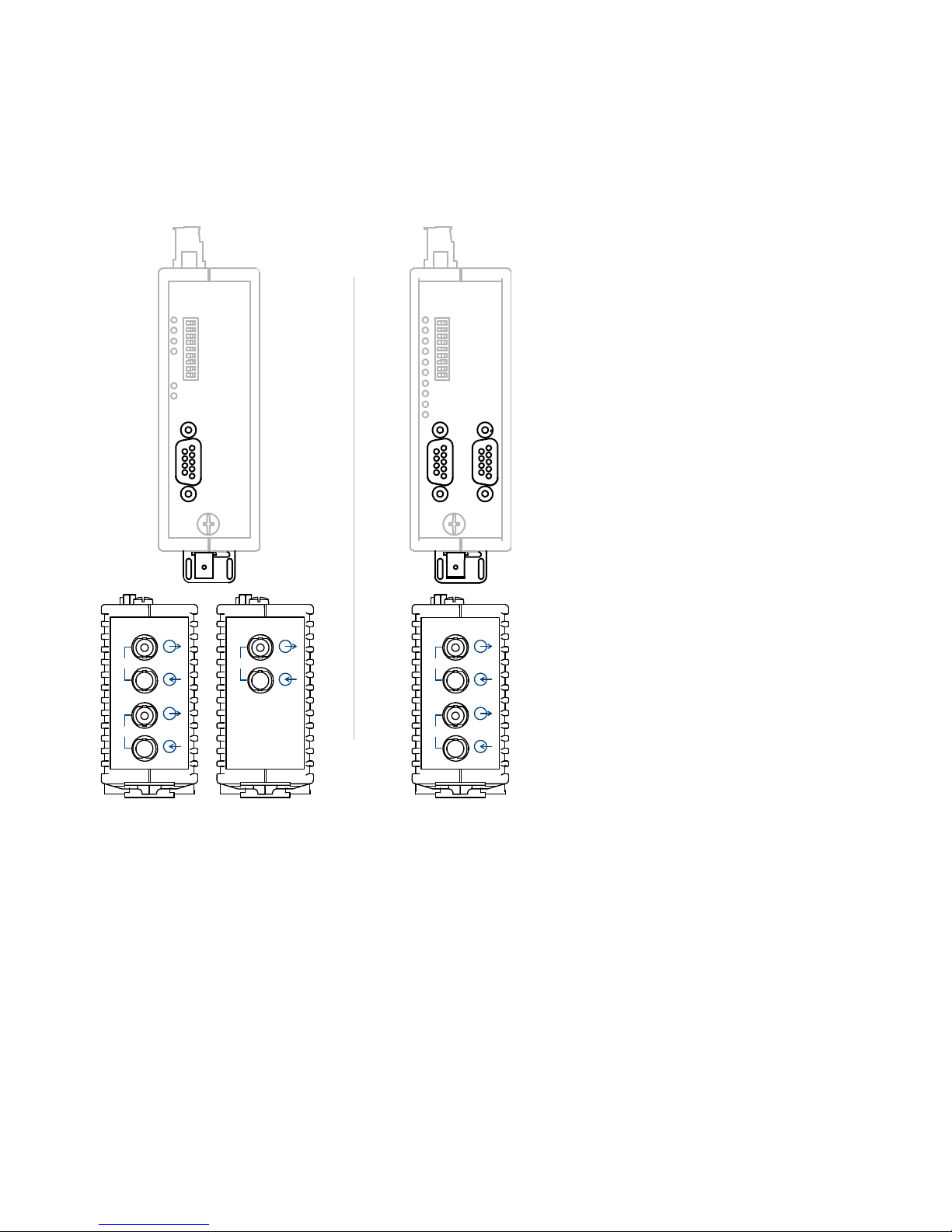
4.5 Connecting the optic bus cables
Proceed as follows:
Use a duplex fiber-optic cable with BFOC/2.5 (ST ®) connectors to
connect the individual repeaters.
Pay attention to the maximum cable length of the fiber-optic cable as well
as the possible types of fibers specified in the Technical Data.
Make sure that each optical input is connected to an optical output at the
opposite end (“cross-overlink“). The corresponding BFOC sockets of the
two ports are marked on the lower front panel.
Ensure sufficient strain relief for the fiber-optic cables and pay attention to
their minimum bend radiuses.
Unused BFOC sockets are to be covered with the protective caps
supplied. Incident ambient light and, in particular, great ambient
brightness, can affect the network. The penetration of dust may impair
operation of the optical components.
Switch S6 to Position 0 (reduced) if overloading is detected at non-OZD
Profi device at CH3.
Switch S7 to Position 0 (reduced) if overloading is detected at a non-OZD
Profi device at CH4.
optical output (Sending direction)
optical input (Receiving direction)
CH 3
CH 4
CH 3
CH 4
CH 1
CH 2
10
S
1
S
0
S
6
S
5
S
3
S
2
S
4
S
7
S 8
CH3

Installation OZD Profi 12M ...
Release 01 07/2017
47
4.6 Connecting the electric bus cables
Figure 7: Assignment of D-Sub socket
Depending on the device variant, the repeaters are fitted with one or two
RS 485 electrical ports. This is a 9-pin D-Sub socket with a screw lock
(inside thread UNC 4-40).
The pin assignment complies with the PROFIBUS standard. At Pin 6
there is a short circuit-proof 5 V output for supplying external pull-up/pulldown resistors.
As opposed to the 24V power supply, the RS 485 bus lines RxD/TxD–N
and RxD/TxD–P are indirect-coupled (functional separation) within SELV
restrictions.
The RS 485 interface is electrically connected to the front panel/function
ground.
Only use shielded and twisted-pair wiring as a RS 485 bus line.
Use a PROFIBUS bus connector plug to connect the RS 485 bus
segment.
5
4
3
2
1
Ground
RTS
RxD/TxD - P
n.c.
n.c.
n.c.
RxD/TxD – N
n.c.
+ 5 V Output
9
8
7
6

48
Installation OZD Profi 12M ...
Release 01 07/2017
Note:
– If the repeater is at the beginning or end of a bus segment, this connector
must have an activated bus terminal resistor combination.
– Ensure that the bus segment connected to the RS 485 interface is
terminated at both ends.
– Only use a connecting cable which is terminated at both ends to connect
a single device.
– All PROFIBUS bus connector plugs in a network must be securely
screwed onto the RS 485 interfaces.
– Attaching or removing the bus connector plugs, inadequately attached
bus connector plugs or loose bus wires within the plug can lead to
malfunctions in the optical and electrical networks.
Proceed as follows:
Attach or remove the RS 485 bus connector plug quickly and without
twisting them.
Remove the RS 485 bus line from the OZD Profi 12M ... if a device is not
connected to the other end, or there is an OZD Profi which has been
disconnected from the power supply. The open line otherwise acts as an
antenna and can cause interference.
When connecting a RS 485 bus line to the OZD Profi 12M … in an active
network, keep to the following sequence in order to avoid interference:
– Place the RS 485 bus connector plug onto the device which is to be
connected (e.g. to a programming device) and screw it on tightly.
– Attach the RS 485 bus connector plug to the OZD Profi 12M ... quickly
and without twisting the connector, and screw it on tightly. Proceed in
the reverse order when removing a device from the network.
Data rate Range per segment
12 Mbit/s 100 m
6 Mbit/s 100 m
3 Mbit/s 100 m
1.5 Mbit/s 200 m
500 kBit/s 400 m
187.5 kBit/s 1000 m
93.75 kBit/s 1200 m
45.45 kBit/s 1200 m
19.2 kBit/s 1200 m
9.6 kBit/s 1200 m
Table 6: Range of RS 485 bus segment with cable type A

Installation OZD Profi 12M ...
Release 01 07/2017
49
Properties of cable type A:
– Characteristic impedance: 135 - 165 Ohm
– Capacity coating: ≤ 30 pF/m
– Loop resistance: ≤ 110 Ohm/km
– Wire diameter: > 0.64 mm
– Wire cross section: > 0.34 mm
2
4.7 Connecting the function ground and the
shield of the bus cable
WARNING
There is no contact separation between the bus lines and the
connection for the function ground.
Observe the following safety instructions:
Do not use bus lines to connect repeaters to device parts which have a
different earth potential. The different voltages could destroy the
repeaters.
Avoid electrical bus lines, which are partly or entirely laid outside
buildings. If lightening strikes close by, this could destroy the repeaters.
Use F/O cables for bus connections outside buildings.
The shield of the bus cable, together with the function ground connection,
must be connected to an equipotential rail in the switch cabinet. The
equipotential rails of the switch cabinets, which are connected to one
another by means of an electrical RS 485 bus cable, must have a lowimpedence connection to one another.
The function ground of the repeater is effected by means of the
connection of the screw terminal block on front of the device.

50
Installation OZD Profi 12M ...
Release 01 07/2017
4.8 Connecting the power supply
Note: To connect the lines for the power supply, remove the 8-pin terminal
block on the top of the repeater from the device.
Proceed as follows:
Only supply the OZD Profi 12M ... with a stabilized safety extra-low
voltage (SELV) in accordance with IEC/EN 60950-1, EN 61131-25, 24 V
maximum. It is supplied via the 8-pin terminal block on the top of the
repeater.
To improve the operating safety, a redundant power supply consisting of
separate sources can be used. You can input the supply voltage in two
ways:
Terminal +24 V (L1+) of the terminal block
Terminal +24 V (L2+) of the terminal block
The minus connection for each is indicated by “0V”.
The two voltages can have any values – even different ones – within the
specified limits.
However, there is no load distribution. If necessary, the power supply unit
with the higher output voltage must supply the power alone.
The supply voltage inputs are protected against incorrect pole connection.
The operating voltage is electrically isolated from the function ground
connection and from the other connections.
L1+
F1
0V
F2
L2+
Ua2
GND
Ua1
+24V
Fault
+24V

Installation OZD Profi 12M ...
Release 01 07/2017
51
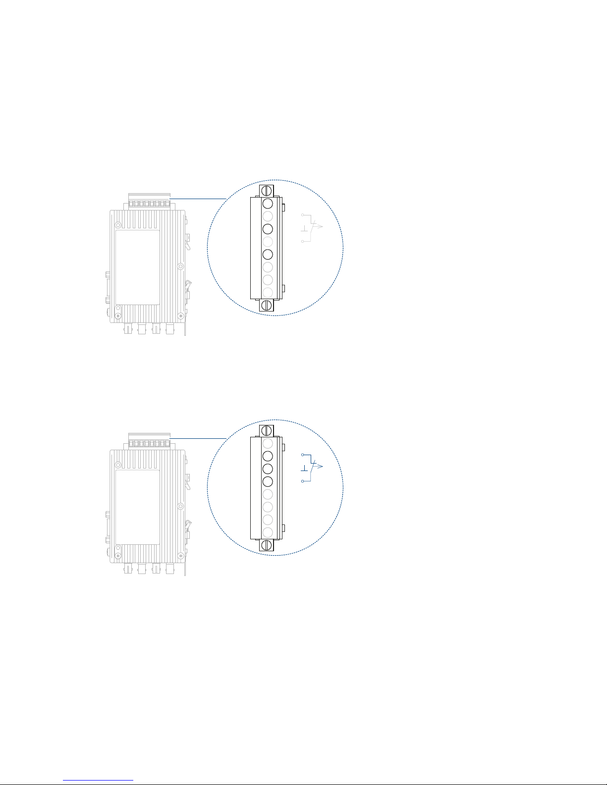
4.9 Connecting the signal contact (optional)
Note:
– To connect the signal contact lines, remove the 8-pin screw terminal block
on top of the repeater from the device.
– Use the correct pin assignment for the 8-pin terminal block.
– Make sure that the electrical insulation of the connection cables of the
signal contacts is sufficient. Incorrect connections can destroy the
repeater.
On the 8-pin terminal block on the top of the repeater, the unconnected pins
of a relay can be used as signal contacts. When the OZD Profi 12M ... is
working correctly, the contact is closed. If there is an error or a power failure,
the contact is opened.
The following problems with the network and the repeater can be signalled
by means of the signal contact:
Supply voltage interrupted
incorrectly connected
Internal device errors
Received data no input signal at port 3 (optical)
(The numbering of the ports depends on device variant)
no input signal at port 4 (optical)
(The numbering of the ports depends on device variant)
faults on port 1 (electrical) or port 2 (electrical)
Redundant optical ring interruption of an optical fiber
a repeater fails
L1+
F1
0V
F2
L2+
Ua2
GND
Ua1
+24V
Fault
+24V

52
Installation OZD Profi 12M ...
Release 01 07/2017
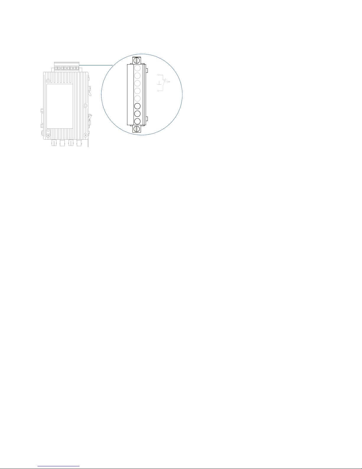
4.10 Connecting the analog voltage outputs
(optional)
Figure 8: Analog voltage outputs – connections for 3-pin terminal block
The device has two analog voltage outputs, Ua1 and Ua2. These voltage
outputs are connected using a 8-pin screw terminal on top of the repeater.
The screw terminal is suitable for cable leads that have a cross section
between 0.2 - 2.5 mm
2
.
The analog voltage outputs supply a short-circuit-proof output voltage
dependent on the optical power input at port 2 or port 3, for diagnosis
purposes and, for example, for preventative maintenance, in the range from
0 - 5 V (each with reference to “GND” of the 8-pin terminal block). The analog
voltage outputs are electrically connected to the front panel/function ground.
The measuring voltage can be determined by a standard volt meter
(ungrounded, high-impedance) . This allows the incoming optical power to be
documented , e.g. for later measurements (aging, damage), a pass/fail
examination to be performed (threshold value), wiring to be carried out on
input terminals of a Profibus I/O module, thereby making the control system
available. As with other process variables, it is possible to define warning
thresholds there and use them for preventative maintenance.
L1+
F1
0V
F2
L2+
Ua2
GND
Ua1
+24V
Fault
+24V

Installation OZD Profi 12M ...
Release 01 07/2017
53
Figure 9: Correlation of measured output voltage to signal quality
Note: For a measured value to be valid, it is necessary that the partner OZD
Profi 12M ... on the other end of the optical fiber transmits regular PROFIBUS
telegrams. An OZD Profi 12M ... is no substitute for a calibrated, optical level
meter. However, it provides each optical port with a voltage derived from the
peak value of the optical PROFIBUS telegram without disrupting the
communication of data. With regular bus operation, this analog voltage can
be used as an indicator for an alteration in optical attenuation. Because data
traffic and temperature can affect the voltage value, you should not set any
warning threshold too close to the actual value.
Signal
output
voltage
0 100 200 300 400 500 600 700 800 900
Optical power input [μW]
1
0
2
0.5
1.5
2.5
3.5
3
4
Reserve

54
Installation OZD Profi 12M ...
Release 01 07/2017
5 Configuration
During configuration, the PROFIBUS network parameter "Slot time" must be
adapted to the network coverage, network topology and the data rate due to
frame delays caused by lines and network components, as well as by
monitoring mechanisms in the network components.
Configuration of redundant optical rings
The following configuration conditions must be fulfilled in the redundant
optical ring See “Redundant ring” on page 30.
– (1) Configuration of a non-existent bus subscriber
– (2) Increasing the retry value to at least 3
– (3) Checking and adjusting the slot time
Use the user-specific profile of the configuration tool to set the parameters
under (2) and (3).
Calculate the slot time with the following equation:
Slot time = a + (b × Length
OF
) + (c × Number
OZD
)
Slot time is the monitoring period in bit times.
Length
OF
is the sum of all the optical fiber lines (segment lengths) in
the network.
Number
OZD
is the number of OZD Profi 12M ... in the network.
Data rate a b c
12 Mbit/s
a
a. Use the values from table 9 if the calculated slot time is smaller than the
minimum slot time indicated in the table.
1651 240 28
6Mbit/s
a
951 120 24
3Mbit/s
a
551 60 24
1.5 Mbit/s
a
351 30 24
500 kBit/s 251 10 24
187.5 kBit/s 171 3.75 24
93.75 kBit/s 171 1.875 24
45.45 kBit/s 851 0.909 24
19.2 kBit/s 171 0.384 24
9.6 kBit/s 171 0.192 24
Table 7: Constants for calculating the slot time at DP standard (redundant optical
ring).

Installation OZD Profi 12M ...
Release 01 07/2017
55
The calculation of the slot time only takes into consideration the optical
network and the connection of bus subscribers to the OZD Profi 12M ...
via an RS 485 bus segment with a respective length of max. 20 m. Longer
RS 485 bus segments must be allowed for by adding them to the
Length
OF
.
Note: When the slot time is configured with a too small value the OZD
Profi 12M ... will, through it’s fault function and fault indications, indicate
such. The System-LED will blink red/green.
Note: Using the OZD Profi 12M G11-1300 and … G12-1300 (EEC) at
data rates of 12 MBit/s, 6 MBit/s, 3 MBit/s and 1.5 MBit/s the minimum slot
times according to the following table must be met.
See table 9 on page 55.
Data rate a b c
12 Mbit/s
a
1651 240 28
6 Mbit/s
a
951 120 24
3 Mbit/s
a
551 60 24
1.5 Mbit/s
a
2011 30 24
500 kBit/s 771 10 24
187.5 kBit/s 771 3.75 24
93.75 kBit/s 451 1.875 24
45.45 kBit/s 851 0.909 24
19.2 kBit/s 181 0.384 24
9.6 kBit/s 171 0.192 24
Table 8: Constants for calculating the slot time at DP/FMS (”universal“) and DP
with S595U (redundant optical ring)
Data rate Minimum slot time
12 MBit/s 3800 t
Bit
6 MBit/s 2000 t
Bit
3 MBit/s 1000 t
Bit
1.5 MBit/s 530 t
Bit
Table 9: Minimum slot time on OZD Profi 12M G11-1300 and OZD Profi 12M G12-
1300 (EEC)

56
Installation OZD Profi 12M ...
Release 01 07/2017
6 Disassembly
To remove the device, pull down on the locking slide.
1

Installation OZD Profi 12M ...
Release 01 07/2017
57
7 Technical data
General technical data
OZD Profi 12M ... P11
P12
G11
G12
G12-EEC
G11-1300
G12-1300
G12-1300-EEC
Dimensions
W × H × D
See “Dimension drawings” on page 60.
Weight approx. 19.75 oz (560 g)
Supply voltage
See “Requirements for connecting electrical wires” on page 6.
Nominal voltage DC 24 V
Voltage range DC incl.
maximum tolerances
18 V ... 32 V
Connection type 8-pin terminal block
Power loss buffer > 10 ms at 20.4 V DC
Overload current protection
at input
Non-replaceable fuse
Back-up fuse for each
voltage input
Nominal rating:
Characteristic:
2A
slow blow
Output voltage/current for
terminal resistors (Pin 6 DSub socket)
5 V DC + 5%, -10%
Peak inrush current < 4 A
Signal contact
See “Requirements for connecting electrical wires” on page 6.
Maximum Switching current 1 A
Maximum switching voltage 60 V DC
Maximum switching capacity max. 30 V DC, resistive load
Signal transmission
Transmission speed 9.6; 19.2; 45.45; 93.75; 187.5; 500 kBit/s 1.5; 3; 6; 12 Mbit/s
Setting transmission rate automatic
Bit error rate <10
-9
Signal processing time
(any input/output)
≤ 6.5 t
Bit
Retimer
Input port 1 to 4
– Signal distortion
– Mean bit length
±30%
±0.12%
Output Port 1 to 4
Mean bit length
±0.01%
Electrical port
Isolation voltage 500 V
Input/output signal RS 485 level

58
Installation OZD Profi 12M ...
Release 01 07/2017
Climatic conditions during operation
Ambient temperature
OZD Profi 12M ...
without “EEC” feature
OZD Profi 12M ... with
feature “EEC”
a
+32 °F ... +140 °F
(0 °C ... +60 °C)
+32 °F ... +140 °F
(0 °C ... +60 °C)
−4 °F ... +140 °F
(−20 °C ... +60 °C)
+32 °F ... +140 °F
(0 °C ... +60 °C)
−4 °F ... +140 °F
(−20 °C ... +60 °C)
Humidity 5 % ... 95 %
(non-condensing)
Air pressure minimum 700 hPa (+9842 ft; +3000 m)
Climatic conditions during storage
Ambient temperature −40 °F ... +158 °F (−40 °C ... +70 °C)
Humidity 5 % ... 95 %
(non-condensing)
Air pressure minimum 700 hPa (+9842 ft; +3000 m)
Pollution degree 2
Protection classes Laser protection Class 1 in compliance with IEC 60825-1
Degree of protection IP20
a. The OZD Profi 12M G12(-1300) can also be supplied in a special design for more severe
environmental conditions. This variant is designated the OZD Profi 12M G12(-1300) EEC.
The DIP switches on the OZD Profi 12M G12(-1300) EEC may also only be operated at
ambient temperatures between +32 °F ... +140 °F (0 °C ... + 60 °C).
Optical port P G G-1300
Wavelength 650 nm 860 nm 1300 nm
Launchable optical power: - - in fiber 10/125 (default) - - -19 dBm
in fiber 50/125 (default) -17 dBm -17 dBm
in fiber 62.5/125 (default) - -13 dBm -17 dBm
in fiber 200/230/125 (default) -17 dBm - in fiber 200/230/125 (reduced) - 13 dBm in fiber 980/1000 (default) -5 dBm - in fiber 980/1000 (reduced) -10 dBm - Receiver sensitivity -25 dBm -28 dBm -29 dBm
Receiver overload limit 0 dBm -1 dBm -3 dBm
Damping values of the fiber
optic
P G G-1300
Wavelength 650 nm 860 nm 1300 nm
Damping values:
Fiber 10/125 - - 0.5 dB/km
Fiber 50/125 - 3 dB/km 1 dB/km
Fiber 62.5/125 - 3.5 dB/km 1 dB/km
Fiber 200/230 10 dB/km 8 dB/km Fiber 980/1000 0.225 dB/m - -
Transmission distance
a
P G G-1300
Wavelength 650 nm 860 nm 1300 nm
System reserve 2 dB 3 dB 2 dB

Installation OZD Profi 12M ...
Release 01 07/2017
59
EMC and immunity
Power consumption/power output
Transmission distance:
Fiber 10/125 - 15000 m
Fiber 50/125 (default) - 3000 m 10000 m
Fiber 62.5/125 (default) - 3000 m 10000 m
Fiber 200/230/125 (default) 400 m - Fiber 200/230/125 (reduced) - 800 m (12 MBit/s)
1000 m
(<12 MBit/s)
-
Fiber 980/1000 (default) 80 m - Fiber 980/1000 (reduced) 57 m - -
a. The specified transmission distance must not be exceeded regardless of the maximum
allowed attenuation line.
EMC interference emission
Radiated emission
EN 55022 Class A
EN 55032 Class A
FCC 47 CFR Part 15 Class A
EMC interference immunity
Electrostatic discharge
EN 61000-4-2
IEEE C37.90.3
Contact discharge ± 4 kV
EN 61000-4-2
IEEE C37.90.3
Air discharge ± 8 kV
Electromagnetic field
EN 61000-4-3 80 MHz ... 1000 MHz 10 V/m
1400 MHz ... 2000 MHz
Fast transients (burst)
EN 61000-4-4
IEEE C37.90.1
DC supply connection ± 2 kV
EN 61000-4-4
IEEE C37.90.1
Data line ± 1 kV
Voltage surges - data line
EN 61000-4-5 line/ground ± 1 kV
Conducted disturbances
EN 61000-4-6 150 kHz ... 80 MHz 10 V
Device name Maximum power consumption Maximum power output
OZD Profi 12M ... 3.9 W (1 electrical port) 13.3 BTU (IT)/h
4.7 W (2 electrical ports) 16 BTU (IT)/h
Transmission distance
a
P G G-1300

60
Installation OZD Profi 12M ...
Release 01 07/2017
Dimension drawings
39,5
110,4
4.35
16,35
0.64
10,75
0.42
12,47
0.49
mm
inch
83,95
3.31
1.56
20
0.79

Installation OZD Profi 12M ...
Release 01 07/2017
61
8 Scope of delivery, order numbers and
accessories
Scope of delivery
Order numbers/product description
Number Article
1× Device
1 × General safety instructions
Device name Order number
OZD Profi 12M G11 942 148-001
OZD Profi 12M G12 942 148-002
OZD Profi 12M G22 942 148-003
OZD Profi 12M G11-1300 942 148-004
OZD Profi 12M G12-1300 942 148-005
OZD Profi 12M G22-1300 942 148-006
OZD Profi 12M P11 942 148-007
OZD Profi 12M P12 942 148-008
OZD Profi 12M P22 942 148-009
OZD Profi 12M G12 EEC 942 148-102
OZD Profi 12M G12-1300 EEC 942 148-105
OZD Profi 12M G22 EEC 942 148-103
OZD Profi 12M G22-1300 EEC 942 148-106

62
Installation OZD Profi 12M ...
Release 01 07/2017
9 Underlying technical standards
The device has an approval based on a specific standard only if the approval
indicator appears on the device casing.
The device generally fulfills the technical standards named in their current
versions.
Name
CSA C22.2 No. 142 Canadian National Standard(s) – Process Control Equipment –
Industrial Products
FCC 47 CFR Part 15 Code of Federal Regulations
UL/IEC 61010-1,
UL/IEC 61010-2-201
Safety for Control Equipment
EN 55022 Information technology equipment – Radio disturbance
characteristics – Limits and methods of measurement
EN 55032 Electromagnetic compatibility of multimedia equipment.
EN 61000-3-2 Electromagnetic compatibility (EMC) - Part 3-2: Limits - Limits for
harmonic current emissions
EN 61000-3-3 Electromagnetic compatibility (EMC) - Part 3-3: Limits - Limitation
of voltage changes, voltage fluctuations and flicker.
EN 61000-6-2 Electromagnetic compatibility (EMC) – Part 6-2: Generic
standards – Immunity for industrial environments
EN 61000-6-4 Electromagnetic compatibility (EMC) – Part 6-4: Generic
standards – Emission standard for industrial environments
EN 61131-2 Programmable controllers – Part 2: Equipment requirements and
tests
Table 10: List of the technical standards

Installation OZD Profi 12M ...
Release 01 07/2017
63
10 Help with problems
10.1 Troubleshooting
This chapter helps you to localize faults after they have been indicated (by
LEDs or signal contacts).
Fault indicated on the system LED
For more details see chapter “Display elements” on page 20.
Fault indicated on CH1, CH2
Make sure that the DIP switch S0 is in Position 1 if the OZD Profi
connected to the electrical star segment of a star topology.
See “Star topology” on page 28.
Make sure that the fault is still displayed after removal of the RS 485
connector.
Still displayed: Device is defective
c
. Replace the OZD Profi.
No longer displayed: The fault lies in the RS485 bus segment.
Check all RS 485 connectors as described in “Connecting the
electric bus cables”.
See “Connecting the electric bus cables” on page 47.
Check the structure and shielding of the RS 485 bus segment.
Check the RS 485 bus segment using a PROFIBUS bus monitor.
Check the configuration of all bus subscribers.
Fault indicated on CH3, CH4
Make sure that optically only repeaters of the same type are
connected together.
See “Network Topologies” on page 24.
Make sure that the optical ports, which are connected via optical
fibers, have been set to the same operating mode.
See “Setting the operating mode and transmitting power” on page 43.
Make sure that the settings given in chapter ”Connecting the optic bus
cables“ have been observed when connecting and laying the optical
bus lines.
See “Connecting the optic bus cables” on page 46.
c. This is not the case if the monomaster of a PROFIBUS network is connected to the RS 485
bus segment which is to be examined. Replace the OZD Profi concerned with another OZD
Profi from the network, and then carry out the test described above.
If the OZD Profi still malfunctions when connected elsewhere, the device is defective.
Replace the OZD Profi.
If the OZD Profi does not malfunction elsewhere, the fault lies in the RS 485 bus segment.
Carry out the measures described above.

64
Installation OZD Profi 12M ...
Release 01 07/2017
10.2 Systematic troubleshooting
This chapter helps you to localize an error systematically with the help of the
following questions.
See also the description of the LED displays. See “Display elements” on
page 20.
Check the following points:
Are all the electrical bus lines terminated at both ends in accordance with
PROFIBUS specification (even for short electrical lines)?
Are the lengths of the optical cables within the threshold values specified
in this manual?
See “Technical data” on page 57.
Is the reception level of the optical ports within the permissible range?
Are the DIP switches set according to the topology, mode of operation,
compatibility and optical transmission power?
See “Setting the operating mode and transmitting power” on page 43.
See “Setting compatibility” on page 40.
Were the following points taken into account regarding topology:
Line topology
Line topology selected and set according to the specifications in chapter
“Line topology” with or without F/O link monitoring.
See “Line topology” on page 25.
Star topology
CH1 must be switched to “Monitor off” mode (S0=1) for all OZD Profi 12M
… connected to the electrical star segment.
Wiring of the electrical star segment must be undertaken with care.
Expansion of the electrical star segment is to be as small as possible.
The electrical star segment must be terminated at both ends.
No bus subscribers are to be connected to the electrical star segment.
Non-busy optical ports are to be switched to “Line without F/O link
monitoring” operating mode.
Redundant optical ring
Both ports of all the OZD Profi 12M … must be set to “Redundant optical
ring” operating mode.
All the OZD Profi 12M … within a ring must be optically linked with one
another.

Installation OZD Profi 12M ...
Release 01 07/2017
65
Note: Configuration (these settings can usually be set on the PROFIBUS
master using configuration software, not on the OZD Profi 12M … ):
– Slot time configured correctly? (for basics, see chapter “Redundant ring”
for calculation, see “TSLOT.exe”)
– Retry value configured correctly? (target value ≥ 3, see chapter
“Redundant ring”).
– Value of MIN T
SDR
configured correctly? (target value ≥ 11, see chapter
Retry).
– In case of redundant optical ring only: “HSA” (Highest Station Address)
configured correctly or “a non-existent bus subscriber” configured?
Note: Check the status of the LEDs and use chapter “Display elements” and
“Troubleshooting” to check the possible causes and resolve the errors
detected.
10.3 Problem reporting
If the transmission in the RS 485 network is still not satisfactory after all the
points in chapter “Display elements” and “Troubleshooting” have been
clarified, then please contact our support with answers to the following
questions:
Exact type designation of the OZD Profi 12M ... . For identification
purposes, please provide the order number printed on the device (18
digits).
What data rate is being used?
How are the DIP switches set on all the devices?
Send us a detailed network plan with the fiber type and fiber length, the
location and length of the electrical segments and the position of the
terminators.
Give as detailed a description of the error as possible in your own words.
Which values were configured for slot time, retry value and MIN T
SDR
?
What is the status of the LEDs on the relevant OZD Profi 12M ... ?
Please provide the voltage values of the analog voltage outputs for the
relevant OZD Profi 12M ... .
See “Connecting the analog voltage outputs (optional)” on page 52.
In case of redundant optical ring only: Which value was configured for
HSA (Highest Station Address)? Was a non-existent bus subscriber
configured?
Note: If you do not provide complete answers to the questions, we cannot
process your query.

66
Installation OZD Profi 12M ...
Release 01 07/2017
A Further support
Technical questions
For technical questions, please contact any Hirschmann dealer in your area
or Hirschmann directly.
You find the addresses of our partners on the Internet at
http://www.hirschmann.com.
A list of local telephone numbers and email addresses for technical support
directly from Hirschmann is available at
https://hirschmann-support.belden.eu.com.
This site also includes a free of charge knowledge base and a software
download section.
Hirschmann Competence Center
The Hirschmann Competence Center is ahead of its competitors on three
counts with its complete range of innovative services:
Consulting incorporates comprehensive technical advice, from system
evaluation through network planning to project planning.
Training offers you an introduction to the basics, product briefing and user
training with certification.
You find the training courses on technology and products currently
available at http://www.hicomcenter.com.
Support ranges from the first installation through the standby service to
maintenance concepts.
With the Hirschmann Competence Center, you decided against making any
compromises. Our client-customized package leaves you free to choose the
service components you want to use.
Internet:
http://www.hicomcenter.com

Installation OZD Profi 12M ...
Release 01 07/2017
67

68
Installation OZD Profi 12M ...
Release 01 07/2017

Installation OZD Profi 12M ...
Release 01 07/2017
69

70
Installation OZD Profi 12M ...
Release 01 07/2017

Installation OZD Profi 12M ...
Release 01 07/2017
71

 Loading...