

Page 1
System
OZD Profi 12M
Receive
Signal
Intensity
CH 1
CH 1
CH 2
CH 2
GND
CH 3
CH 3
Manual
PROFIBUS Repeater OZD Profi 12M …
Page 2

2
Order Numbers
OZD Profi 12M P11 943 728-221
OZD Profi 12M P12 943 728-321
OZD Profi 12M G11 943 727-221
OZD Profi 12M G12 943 727-321
OZD Profi 12M G12-EEC 943 730-321
OZD Profi 12M G11-1300 943 729-221
OZD Profi 12M G12-1300 943 729-321
OZD Profi 12M G12-1300 EEC 943 256-321
Description and Operating Instructions 039 629-001
PROFIBUS-Repeater OZD Profi 12M …
Description and Operating Instructions are protected by copyright.
All rights reserved.
The reproduction, duplication, translation, conversion to any electronic
medium or machine-readable form in whole or in part is not permitted
The following Description and Operating Instructions have been
produced by Hirschmann Automation and Control GmbH to the best of
the company's knowledge.
Hirschmann reserves the right to amend the contents of this Description
and Operating Instructions without prior notice.
Hirschmann cannot provide any warranty or guarantee with regard
to the correctness or accuracy of the information contained in this
Description and Operating Instructions.
Under no circumstances can Hirschmann be held liable for any damage
arising from the use of the PROFIBUS-Repeater OZD Profi 12M … .
© 2007 Hirschmann Automation and Control GmbH
The naming of registered trademarks in the following Description and
Operating Instructions, even if not specifically identified as such, should
not warrant the assumption that such names are not subject to the
terms stipulated in the trademark and trademark protection legislation
and that they can therefore be freely used by anyone.
Page 3

3
Version 2.4 04/07
Contents
1 Introduction . . . . . . . . . . . . . . . . . . . . . . . . . . . . . . . . . . . . . . . . . . . . . . . . . . . . . . . . . . . . . . . . . . . . . . . . . . 5
2 General Functions . . . . . . . . . . . . . . . . . . . . . . . . . . . . . . . . . . . . . . . . . . . . . . . . . . . . . . . . . . . . . . . . . . . . 7
2.1 Non operating mode related functions . . . . . . . . . . . . . . . . . . . . . . . . . . . . . . . . . . . . . . . . . . . . . . 7
2.2 Operating mode related functions . . . . . . . . . . . . . . . . . . . . . . . . . . . . . . . . . . . . . . . . . . . . . . . . . 7
3 Network Topologies . . . . . . . . . . . . . . . . . . . . . . . . . . . . . . . . . . . . . . . . . . . . . . . . . . . . . . . . . . . . . . . . . . . 9
3.1 Line topology . . . . . . . . . . . . . . . . . . . . . . . . . . . . . . . . . . . . . . . . . . . . . . . . . . . . . . . . . . . . . . . . . 9
3.1.1 Line topology with optical fiber link monitoring and segmentation . . . . . . . . . . . . . . . . . . 10
3.1.2 Line topology without optical fiber link monitoring . . . . . . . . . . . . . . . . . . . . . . . . . . . . . . 11
3.2 Star topology . . . . . . . . . . . . . . . . . . . . . . . . . . . . . . . . . . . . . . . . . . . . . . . . . . . . . . . . . . . . . . . . . 12
3.3 Redundant optical ring . . . . . . . . . . . . . . . . . . . . . . . . . . . . . . . . . . . . . . . . . . . . . . . . . . . . . . . . . . 13
4 Setting Up . . . . . . . . . . . . . . . . . . . . . . . . . . . . . . . . . . . . . . . . . . . . . . . . . . . . . . . . . . . . . . . . . . . . . . . . . . . . . 15
4.1 Safety notice . . . . . . . . . . . . . . . . . . . . . . . . . . . . . . . . . . . . . . . . . . . . . . . . . . . . . . . . . . . . . . . . . 15
4.2 Notes on CE marking . . . . . . . . . . . . . . . . . . . . . . . . . . . . . . . . . . . . . . . . . . . . . . . . . . . . . . . . . . . 16
4.3 General information about setting up . . . . . . . . . . . . . . . . . . . . . . . . . . . . . . . . . . . . . . . . . . . . . . . 16
4.4 Setting compatibility, operating mode and transmitting power . . . . . . . . . . . . . . . . . . . . . . . . . . . 17
4.4.1 Setting the compatibility . . . . . . . . . . . . . . . . . . . . . . . . . . . . . . . . . . . . . . . . . . . . . . . . . . . 17
4.4.2 Setting the operating mode . . . . . . . . . . . . . . . . . . . . . . . . . . . . . . . . . . . . . . . . . . . . . . . . 18
4.4.3 Reducing the optical transmitting power on the OZD Profi 12M P11 . . . . . . . . . . . . . . . . 19
and OZD Profi 12M P12
4.5 Installation . . . . . . . . . . . . . . . . . . . . . . . . . . . . . . . . . . . . . . . . . . . . . . . . . . . . . . . . . . . . . . . . . . . 20
4.5.1 Installation guidelines . . . . . . . . . . . . . . . . . . . . . . . . . . . . . . . . . . . . . . . . . . . . . . . . . . . . 20
4.5.2 Connecting the optical lines . . . . . . . . . . . . . . . . . . . . . . . . . . . . . . . . . . . . . . . . . . . . . . . .22
4.5.3 Mounting the modules . . . . . . . . . . . . . . . . . . . . . . . . . . . . . . . . . . . . . . . . . . . . . . . . . . . .22
4.5.4 Connecting the electric RS 485 bus lines . . . . . . . . . . . . . . . . . . . . . . . . . . . . . . . . . . . . . 24
4.5.5 Connecting the power supply . . . . . . . . . . . . . . . . . . . . . . . . . . . . . . . . . . . . . . . . . . . . . . 25
4.5.6 Connecting the signaling contact lines . . . . . . . . . . . . . . . . . . . . . . . . . . . . . . . . . . . . . . . 25
4.5.7 Defining the receiving level of the optical ports . . . . . . . . . . . . . . . . . . . . . . . . . . . . . . . . . 26
5 LED Indicators and Troubleshooting . . . . . . . . . . . . . . . . . . . . . . . . . . . . . . . . . . . . . . . . . . . . . . . . . 27
5.1 LED Indicators . . . . . . . . . . . . . . . . . . . . . . . . . . . . . . . . . . . . . . . . . . . . . . . . . . . . . . . . . . . . . . . . 27
5.2 Troubleshooting . . . . . . . . . . . . . . . . . . . . . . . . . . . . . . . . . . . . . . . . . . . . . . . . . . . . . . . . . . . . . . . 29
6 Configuration . . . . . . . . . . . . . . . . . . . . . . . . . . . . . . . . . . . . . . . . . . . . . . . . . . . . . . . . . . . . . . . . . . . . . . . . . 31
6.1 Configuration of redundant optical rings . . . . . . . . . . . . . . . . . . . . . . . . . . . . . . . . . . . . . . . . . . . . 31
7 Technical Data . . . . . . . . . . . . . . . . . . . . . . . . . . . . . . . . . . . . . . . . . . . . . . . . . . . . . . . . . . . . . . . . . . . . . . . . 33
Contents
Page 4

Contents
4
Version 2.4 04/07
8 Appendix . . . . . . . . . . . . . . . . . . . . . . . . . . . . . . . . . . . . . . . . . . . . . . . . . . . . . . . . . . . . . . . . . . . . . . . . . . . . . . 33
8.1 FCC conformity . . . . . . . . . . . . . . . . . . . . . . . . . . . . . . . . . . . . . . . . . . . . . . . . . . . . . . . . . . . . . . . 35
8.2 FM approval . . . . . . . . . . . . . . . . . . . . . . . . . . . . . . . . . . . . . . . . . . . . . . . . . . . . . . . . . . . . . . . . . 35
8.3 Ex approval . . . . . . . . . . . . . . . . . . . . . . . . . . . . . . . . . . . . . . . . . . . . . . . . . . . . . . . . . . . . . . . . . . 35
8.4 UL/CSA-Zulassung . . . . . . . . . . . . . . . . . . . . . . . . . . . . . . . . . . . . . . . . . . . . . . . . . . . . . . . . . . . . 35
8.5 C-Tick . . . . . . . . . . . . . . . . . . . . . . . . . . . . . . . . . . . . . . . . . . . . . . . . . . . . . . . . . . . . . . . . . . . . . . 36
8.6 Literature notes . . . . . . . . . . . . . . . . . . . . . . . . . . . . . . . . . . . . . . . . . . . . . . . . . . . . . . . . . . . . . . . 36
8.7 List of abbreviations . . . . . . . . . . . . . . . . . . . . . . . . . . . . . . . . . . . . . . . . . . . . . . . . . . . . . . . . . . . . 36
8.8 Measuring sockets . . . . . . . . . . . . . . . . . . . . . . . . . . . . . . . . . . . . . . . . . . . . . . . . . . . . . . . . . . . . . 37
9 Application Support . . . . . . . . . . . . . . . . . . . . . . . . . . . . . . . . . . . . . . . . . . . . . . . . . . . . . . . . . . . . . . . . . . . 38
Page 5
5
1 Introduction
Version 2.4 04/07
1 Introduction
The PROFIBUS Repeaters OZD Profi 12M …
䡲 OZD Profi 12M P11,
䡲 OZD Profi 12M P12,
䡲 OZD Profi 12M G11,
䡲 OZD Profi 12M G12,
䡲 OZD Profi 12M G12 EEC,
䡲 OZD Profi 12M G11-1300,
䡲 OZD Profi 12M G12-1300 and
OZD Profi 12M G12-1300 EEC
are designed to be used in optical PROFIBUS field bus
networks. They enable electrical PROFIBUS interfaces
(RS 485 level) to be converted into optical PROFIBUS
interfaces and vice-versa.
Table 1, p. 6 shows the different methods for connecting
the modules, and the maximum optical ranges of each
port.
By profiting from the familiar advantages of optical transmission technology, the modules can be integrated into
existing PROFIBUS field bus networks.
A complete PROFIBUS field bus network with modules in
line, star or ring topology, and an arbitrary combination
of these, can also be built up.
The redundant ring is also supported, thereby increasing
the fail-safety of the field bus network.
Each module has two or three mutually independent
ports, which in turn consist of a transmitting and a
receiving component.
The device is powered by 24V DC voltage. A redundant
feed increases operational safety.
The electric port is a 9-pole Sub-D socket (female). An
RS 485 bus segment in line with the PROFIBUS standard
EN 50170 can be connected to this port.
The optical fibers are connected using BFOC /2.5 (ST
®
)
connectors.
Four multicolored light-emitting diodes indicate the
current operating status and possible operating malfunctions.
One measuring output is available for each optical port
where the optical input level can be measured using a
conventional voltmeter.
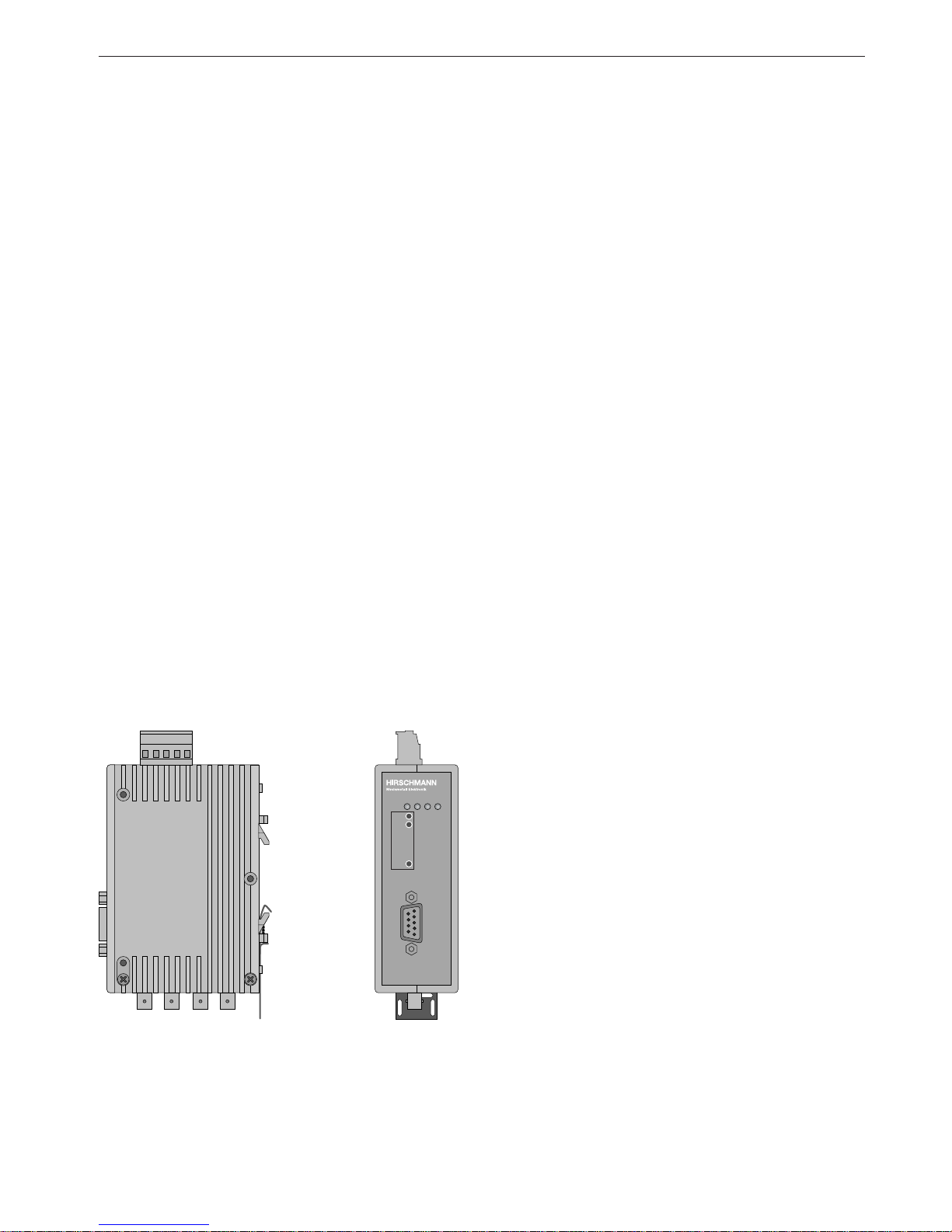
System
OZD Profi 12M
Receive
Signal
Intensity
CH 1
CH 1
CH 2
CH 2
GND
CH 3
CH 3
Operating voltage supply /
signaling contact
5-pole terminal block
Port 1
electric,
Sub-D socket
Port 2
optical,
BFOC/2.5
socket
Port 3
optical,
BFOC/2.5
socket
LED Indicators
Measuring
sockets
Fig.1: OZD Profi 12M … module showing the location of the
LED indicators, measuring sockets and the individual ports.
Page 6

1 Introduction
6
Version 2.4 04/07
Different OZD Profi 12M … malfunction reports are provided as an accumulative signal via a signaling contact
(relay with unconnected contacts) for further processing.
The mechanical design consists of a compact, stable
metal housing which can be mounted on a hat rail or
mounting plate as required.
The module is configured using easily accessible
switches.
The OZD Profi 12M … complies with the standard
EN 50170 and the technical guidelines issued by the
PROFIBUS user organization, PNO, ”PROFIBUS optical
transmission technology“.
OZD Profi 12M G12 and OZD Profi 12M G12-EEC have
the same function. They only differ in the specification
of the climatic ambient conditions: while the OZD Profi
12M G12 is suitable for employment in the standard
temperature range from 0°C to 60°C, the OZD Profi
12M G12-EECC (extended environmental conditions)
can be used in the extended temperature range from –
20°C to +60°C and at up to 100% humidity.
OZD Profi 12M P11 P 12 G11 G12 G11-1300 G12–1300
G12-EEC G12–1300 EEC
Number of ports
– electrical 1111 1 1
– optical 1212 1 2
Fiber types
– Plastic optical fibers
980/1000 µm 80 m 80 m – – – –
– PCF optical fibers
200/230 µm 400 m 400 m – – – –
– Quartz glass optical fibers
10/125 µm –––– 15 km15 km
50/125 µm – – 3000 m 3000 m 10 km 10 km
62.5/125 µm – – 3000 m 3000 m 10 km 10 km
Table 1: Number of electrical and optical ports per module, fiber types which can be used, as well as the maximum possible optical
fiber distances between two modules. See Technical Data, p. 33 for more details about ambient conditions.
PCF stands for Polymer Cladded Fiber, and is the same as HCS
®
. HCS is a registered trademark of Ensign-Bickford
Optics Company.
Page 7

2.1 Non operating mode related functions
7
2 General Functions
Version 2.4 04/07
2 General Functions
Transmission rate
The OZD Profi 12M … support all the transmission
speeds (transmission rates) defined in the EN 50170
standard:
9.6 kBit/s, 19.2 kBit/s, 45.45 kBit/s, 93.75 kBit/s,
187.5 kBit/s and 500 kBit/s,
and additionally
1.5 MBit/s, 3 MBit/s, 6 MBit/s and 12 MBit/s.
The transmission rate is set automatically as soon as the
OZD Profi 12M … receives a frame. The setting or adjustment is dependent on the transmission rate and the
set operating mode. Depending on the OZD Profi 12M … ,
this can last up to several seconds.
If the transmission speed has not been recognized, the
outputs of all ports are blocked. If the transmission rate
changes during operation, this is detected by the modules, which then automatically adjust their settings accordingly.
Transfer malfunctions may temporarily occur while the
rate is being altered.
Signal regeneration
The modules regenerate the signal form and amplitude
of the data received. This allows up to 122 OZD Profi
12M … to be cascaded (limited by the address space in
PROFIBUS networks).
Help when setting up
At least one bus subscriber must be switched on and
active in order to check the optical fiber connections
during the installation. This bus subscriber serves as the
frame source. The OZD Profi 12M … act passively when
it is switched on. They recognize the transfer speed from
the frames sent by the bus subscriber. An optical help
when putting the device into operation is provided by the
port LED which then lights up.
The operating mode is set using switches located on the
top of the module. A sticker attached to the side of the
module provides assistance with the settings.
Segment monitoring at the RS 485 port
If the operating mode ”Electric port with segment monitoring“ is set, each receiver monitors the RS 485 bus
segment connected to it for faulty frames or continuously
busy networks. If faulty frames are received by the receiver,
or if the network is busy for longer than the maximum
permitted send time, forwarding of the received signals
is blocked until frames can be received again correctly,
or if no signal is received for one second.
The RS 485 bus segment is not monitored in the operating mode ”Electric port without segment monitoring“.
Interference from the electrical segment affects the entire
network.
Please observe the installation notes in 4.5.4. ”Connecting the electric RS 485 bus lines“, p. 24.
The following functions are only available for the optical
ports. Whether the functions can be activated depends
on the operating mode which has been set. Please refer
to the following chapters for details.
2.1 Non operating mode related functions
2.2 Operating mode related functions
Page 8

2 General Functions 2.2 Operating mode related functions
8
Version 2.4 04/07
Line monitoring with echoes
The modules enable the connected optical paths to be
actively monitored for interruptions in the fiber line by
means of the functions ”Send echo“, ”Monitor echo“ and
”Suppress echo“.
Send echo
A frame which is received by a module via any port is
transmitted to all other ports. If the receiving port is an
optical port, the module sends the frame back to the
corresponding optical sender.
Monitor echo
If a module sends a frame - no echo! – to an optical port,
the module expects to receive an echo. If the echo is not
received after a predefined time, an echo monitoring
error is indicated by a red LED belonging to the port.
Suppress echo
The relevant receiver is separated from the other ports
from the moment a frame is sent until the echo has been
received correctly.
Segmentation
If an echo monitoring error or a frame falsification arises
at an optical port, the module assumes that the line is
faulty and blocks this port for user data. The connected
field bus partial network is then segmented (cut off). This
segmentation causes the module at the other end of the
optical fiber to be segmented as well.
Both modules connected to the segmented field bus
partial network send test frames to the segmented ports.
These test frames – which are to be received regularly –
can be used by both modules to check the status of the
field bus partial network.
The segmentation is automatically lifted as soon as the
test frames indicate to both modules that the segmented
field bus partial network is no longer disturbed.
If all active bus subscribers are deactivated in a previously
active network, the modules are segmented cyclically in
order to check the fiber links to the neighboring modules.
If there is no frame traffic, but the fiber links are intact,
the port LEDs of the optical ports flash yellow cyclically.
Page 9

3.1 Line topology
9
3 Network Topologies
Version 2.4 04/07
3 Network Topologies
The following network topologies can be realized with the
OZD Profi 12M … :
䡲 Point-to-point connections
䡲 Line topologies
䡲 Star topologies
䡲 Redundant optical rings
Combinations of these basic types are also possible.
Lines with two optical fibers are used to create the fiber
links for these network topologies.
If a malfunction – e.g. a break in a fiber line – makes a
high degree of field bus network fail-safety necessary,
the availability of the network can be increased using a
redundant network configuration.
Please note:
䡲 Single terminals or entire PROFIBUS segments
with max. 31 subscribers can be connected to the
electrical interface of the OZD Profi 12M … .
䡲 In areas with a high EMC incidence, only lay opti-
cal fiber lines in order to exclude the possibility of
EMC affecting the whole network.
䡲 Optically only OZD Profi 12M … of the same
type can be connected together:
– OZD Profi 12M P11 with … P12
– OZD Profi 12M G11 with … G12 and …G12 EEC
– OZD Profi 12M G11-1300 with … G12-1300
and …G12-1300 EEC
䡲 Optical ports which are connected by optical fiber
must be set to the same operating mode.
䡲 Junctions between different OZD Profi 12M …
types are only possible via the RS485 interface.
䡲 OZD Profi 12M G12(-1300) EEC can be used every-
where in those network topologies described
below in which a OZD Profi 12M G12(-1300) can
also be used.
3.1 Line topology
Fig. 2: Network structure in an optical line topology
CH 2
TR
CH 2
TR
CH 3
TR
OZD … P11
OZD … G11 (-1300)
OZD … P12
OZD … G12 (-1300)
CH 1
CH 1
Terminal unit /
bus segment
CH 2
TR
OZD … P11
OZD … G11 (-1300)
CH 1
Terminal unit /
bus segment
Terminal unit /
bus segment
CH 2
TR
CH 3
TR
OZD … P12
OZD … G12 (-1300)
CH 1
Terminal unit /
bus segment
RS 485 bus line
Optical fiber
Page 10

3 Network Topologies 3.1 Line topology
10
Version 2.4 04/07
3.1.1 Line topology with optical fiber link
monitoring and segmentation
This operating mode should preferably be used if an
interrupted fiber segment is to be separated from the
rest of the network.
䡲 Monitoring mechanisms:
Send echo: yes
Monitor echo: yes
Suppress echo: yes
Monitor: yes
Segmentation: yes
In this operating mode the individual fiber links are monitored by the two connected modules.
If a module fails, an optical fiber breaks or faults are
determined on the optical transfer link, the fiber link
between the two OZD Profi 12M … is interrupted
(segmented).
The PROFIBUS network is divided into two partial networks, which remain functional independently of one
other.
The malfunction is indicated at the two OZD Profi 12M …
is connected to the malfunctioning fiber link by the port
LEDs switching to red and by activation of the signaling
contacts. The segmentation is lifted automatically as
soon as both modules recognize that the field bus network is functioning correctly with the help of test frames.
Please note that in the case of networks with several
active bus subscribers, two logical token rings are
formed in the event of an error. Every time the partial
networks are switched together, network malfunctions
may arise due to the double tokens or frame collisions.
Note:
If a module with two optical ports is used at the
beginning or end of a line, the optical port which is
not assigned must be switched to the operating mode
”Line without fiber link monitoring“, so that it does not
signal a break in the fiber line.
Please note that optical ports which are not connected
must always be fitted with protective caps to guard
against extraneous light and dirt.
In a line structure, the individual OZD Profi 12M … are
connected together by dual-fiber optical fibers. Modules
with one optical port are sufficient at the beginning and
end of a line, between which modules with two optical
ports are necessary.
If single point-to-point connections are to be built up,
this can be achieved using two modules each with one
optical port.
The line topology can be realized with and without fiber
link monitoring. If both operating modes are used within
an optical fiber line, the operating mode ”Line topology
without fiber link monitoring“ determines the availability
of this fiber line. It is recommended that fiber link monitoring be used in homogeneous OZD Profi networks
(default factory setting).
Please note that the following ambient conditions must
be fulfilled to ensure that network configuration functions
correctly:
䡲 The parameters MIN T
SDR
described in the
PROFIBUS standard EN 50170 must be set to a
value >_ 11 on all terminals. This is usually the
case, but the setting should be checked if communication malfunctions continuously arise.
䡲 When configuring your network, select low bus
subscriber addresses wherever possible. This
ensures that master timeout times which may arise
are kept as short as possible in the event of a malfunction.
Refer to the manufacturer’s manual of the terminal concerned for details about how to alter the settings.
Page 11

3.1 Line topology
11
3 Network Topologies
Version 2.4 04/07
3.1.2 Line topology without optical fiber
link monitoring
Use this operating mode if you connect a OZD Profi
12M … with another optical fiber network component,
which does not send a frame echo and does not expect
or is not compatible with a frame echo in accordance
with PROFIBUS guidelines (optical/electrical converter).
䡲 Monitoring mechanisms:
Send echo: no
Monitor echo: no
Suppress echo: no
Monitor: no
Segmentation: no
Individual fiber links are not monitored in this operating
mode.
Page 12
3 Network Topologies 3.2 Star topology
12
Version 2.4 04/07
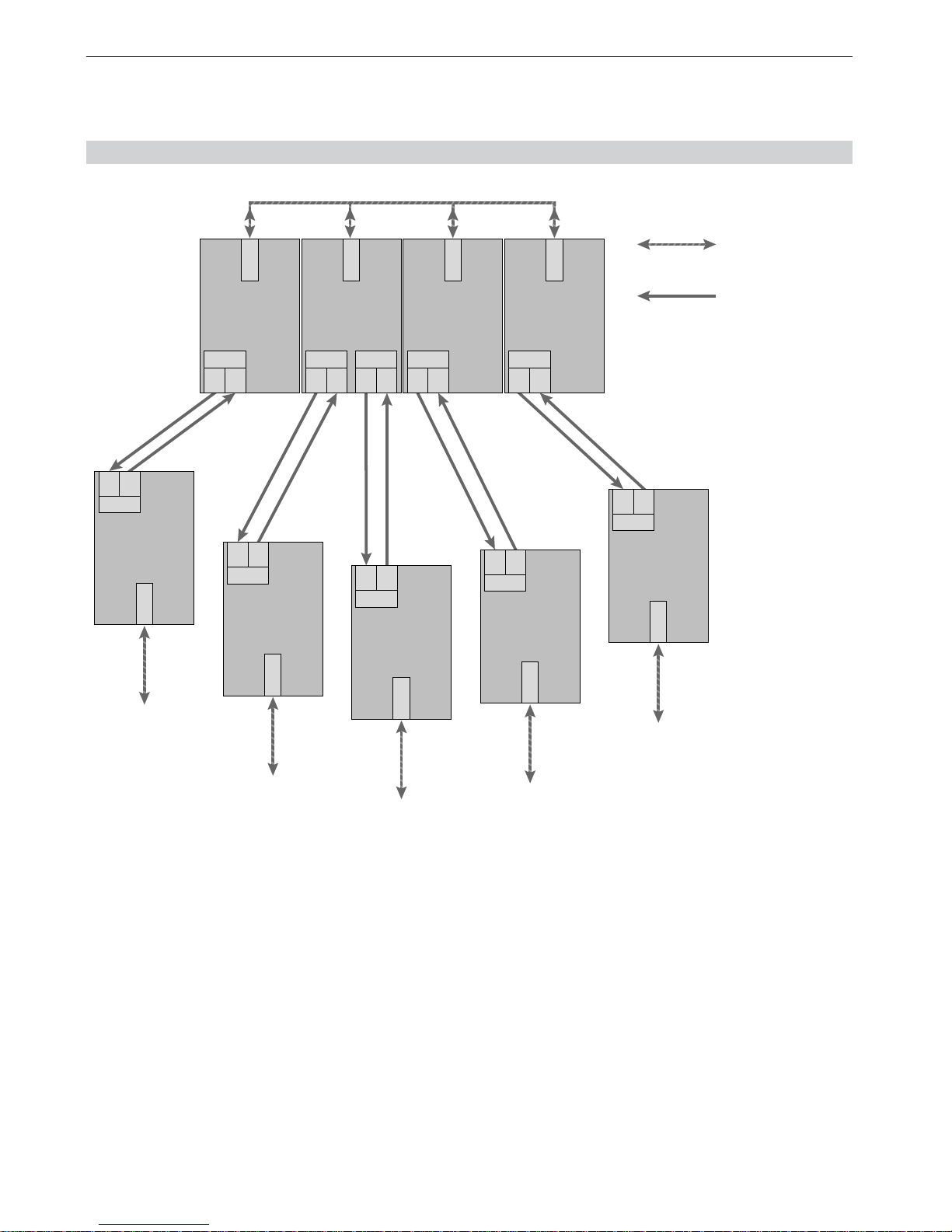
3.2 Star topology
Fig. 3: Network structure in an optic star topology
Terminal unit /
bus segment
Terminal unit /
bus segment
Terminal unit /
bus segment
Terminal unit /
bus segment
Terminal unit /
bus segment
CH 2
TR
OZD … P11
CH 1
CH 2
TR
OZD … P11
CH 1
CH 2
TR
CH 3
TR
OZD … G12
CH 1
CH 2
TR
OZD … G11-1300
CH 1
OZD … P11
CH 2
TR
CH 1
OZD … G11-1300
CH 2
TR
CH 1
OZD … P11
CH 2
TR
CH 1
OZD … G11
CH 2
TR
CH 1
OZD … G11
CH 2
TR
CH 1
Electrical star segment
S0 = 1 S0 = 1 S0 = 1 S0 = 1
RS 485 bus line
Optical fiber
Several modules are combined to form an active PROFIBUS star coupler. Other modules are connected to this
by dual-fiber optical fiber lines. The modules of the star
coupler are connected to one another via the electrical
port (electrical star segment).
All OZD Profi types for different fiber types (plastic, PCF,
glass) can be combined using the electrical star segment.
Please note:
䡲 CH1 in mode ”Monitor off“ (S0 = 1) must be acti-
vated on all OZD Profi 12M … which are connected
to the electrical star segment. This deactivates the
segmenting function of the RS 485 port on these
OZD Profi 12M …, providing a high degree of availability of the electrical star segment.
Page 13

3.2 Star topology
13
3 Network Topologies
Version 2.4 04/07
Fig. 4: Network structure in a redundant optical ring topology
RS 485 bus line
Optical fiber
Terminal unit /
bus segment
OZD … P12
OZD … G12 (-1300)
CH 1
CH 3
TR
CH 2
TR
Terminal unit /
bus segment
OZD … P12
OZD … G12 (-1300)
CH 1
CH 3
TR
CH 2
TR
Terminal unit /
bus segment
OZD … P12
OZD … G12 (-1300)
CH 1
CH 3
TR
CH 2
TR
Terminal unit /
bus segment
OZD … P12
OZD … G12 (-1300)
CH 1
CH 3
TR
CH 2
TR
3.3 Redundant optical ring
䡲 Ensure that the electrical star segment is wired
carefully. Keep it as small as possible to avoid
interference injection into the electrical star
segment, and from here into the entire network.
This can be achieved by laying out the OZD Profi
12M … in the electrical star segment directly next
to each other on a hat rail.
䡲 Switch on the terminating resistors in the bus port
connectors (see 4.5.4, ”Connecting the electric RS
485 bus lines“, p. 24) at both ends of the electrical
star segment.
䡲 Do not connect a bus subscriber to the electrical
star segment wherever possible.
Modules with one or two optical ports can be used to
create an active PROFIBUS star coupler. Modules with
one optical port are sufficient for connecting a terminal
or an RS 485 bus segment to the active star coupler.
If the link monitoring on the optical ports is activated,
the fiber optic links are monitored by the respectively
connected OZD Profi 12M ….
Note:
Optical ports which are not assigned (for instance,
because they are reserved for a future system extension)
indicate a fiber break if the link monitoring is activated.
You can prevent this error report from being issued by
activating the operating mode ”Line without fiber link
monitoring “ at the non-assigned ports.
Please note that optical ports which are not connected
must always be fitted with protective caps to guard
against extraneous light and dirt.
Page 14

3 Network Topologies 3.3 Redundant optical ring
14
Version 2.4 04/07
This network topology represents a special form of line
topology. A high degree of network operating safety
is achieved by ”closing“ the optical line. A redundant
optical ring can only be realized with modules with two
optical ports of the same type.
䡲 Monitoring mechanisms:
Send echo: yes
Monitor echo: yes
Suppress echo: yes
Segmentation: yes
An interruption of one or both optical fibers between two
modules is detected by the OZD Profi 12M … and the
ring is transformed into an optical line.
If one module fails only those terminals connected to this
module or the RS 485 segment are uncoupled from the
ring. The remainder of the network itself continues to
function as a line. The error is indicated by the LEDs on
the two OZD Profi 12M … connected to the malfunctioning optical fiber and their signaling contacts.
The segmentation is lifted automatically as soon as both
modules recognize that the segmented field bus network
is functioning correctly with the help of test frames. The
line forms itself into a ring.
Please note:
The following ambient conditions must be fulfilled to
ensure that the network configuration functions correctly:
䡲 The operating mode ”Redundant optical ring“
must be set at both optical ports of all the
OZD Profi 12M ….
䡲 All modules in a ring must be connected to one
another by fiber lines. The ring may not include an
RS 485 bus line.
䡲 The parameter MIN T
SDR
described in the PROFIBUS standard EN 50170 must be set to a value
>_ 11 on all terminals. This is usually the case, but
the setting should be checked if communication
malfunctions continuously arise.
䡲 When configuring your network, select low bus
subscriber addresses wherever possible. This
ensures that master timeout times which may
arise are kept as short as possible in the event
of a malfunction.
䡲 If a redundancy case occurs (e.g. a line break),
there is a switching time during which data cannot
be correctly transmitted. In order to ensure a
smooth transition, it is recommended that the
frame repeat setting (Retry) on the PROFIBUS
master be set to at least 3.
After the error has been corrected, no frames
should be present in the network when the optical
line is transformed back into an optical ring to
ensure that the process is completed smoothly.
This condition can arise when a master selects a
device whose address has been configured, but
which does not physically exist.
The master tries to address this device cyclically
and waits for a reply only until the configured slot
time has been exceeded (”GAP request“). The
OZD Profi 12M … recognizes this condition and
closes the optical line to an optical ring in the
middle of this request sequence.
This results in two configuration requirements for
the redundant optical ring:
– The value of the parameter HSA (Highest Station
Address) must be set at all terminals so that between the bus address 0 and the value HSA at
least one address in the network has not been
assigned to a bus subscriber, i.e. so that there is
at least one address gap. This address gap can
also be created by simply setting the value of the
parameter HSA so that it is at least one greater
than the highest number of subscriber bus
addresses present in the network.
Attention: If this requirement is not or no longer
fulfilled, the optical line will no longer be closed
into a redundant optical ring after segmentation.
The error report (LED and signaling contact) of
the two affected OZD Profi 12M … is not cancelled even after the error has been corrected.
– The slot time must be set to approximately twice
the value required in a non-redundant network.
Further information can be found in Chapter 6
”Configuration“, p. 31.
Refer to the manufacturer’s documentation provided
with the terminal or configuration software for details
about how to adjust the settings.
Page 15

4.1 Safety notice
15
4 Setting Up
Version 2.4 04/07
4 Setting Up
Only use the OZD Profi 12M … as described in
this ”Description and Operating Instructions“.
Pay particular attention to all the warnings and
safety instructions.
Only operate the modules with a safety extra-low
voltage in accordance with IEC 950/EN 60 950/
VDE 0805 with a maximum rating of +32 VDC
(typically +24 VDC).
The power source must comply with NEC, Class 2,
regulations as stipulated by UL/CSA.
Pay attention to the electrical limit values when
connecting the power supply to the signaling
contacts:
max. voltage 60 VDC, 42 VAC.
The connected power supply must also be safety
extra-low voltage in accordance with IEC 950/
EN 60 950/ VDE 0805 and comply with NEC,
Class 2, regulations as stipulated by UL/CSA.
DANGER: Never connect the OZD Profi 12M … to
the main power supply.
Only install the device in a location where the
climatic and mechanical limit values given in the
Technical Data can be complied with.
WARNING: Do not look directly into the aperture of
the optical transmitting diode or the optical fiber.
The light beam which is emitted could endanger
your eyesight.
WARNING: All OZD Profi 12M … are approved for
use in Zone 2 explosive hazardous areas as defined
by EEx nC [L] IIC T5. If used in those areas, the
modules must be installed in a housing (switch
cabinet) with protection class IP 54 as per IEC 529.
4.1 Safety notice
OZD Profi 12M P11
OZD Profi 12M P12
OZD Profi 12M G11-1300
OZD Profi 12M G12-1300
OZD Profi 12M G12-1300 EEC
The optical radiated power of the components used in this device does not
represent a potential health hazard of any description under normal, foreseeable conditions, and it complies with Class 1 in accordance with IEC
60825-1:1994+A1:1997 resp. the Degree of Endangerment 1 in accordance
with IEC 60825-2:1993.
OZD Profi 12M G11
OZD Profi 12M G12
OZD Profi 12M G12-EEC
Non-visible LED radiation.
Do not look into the beam, not even with optical instruments. LED class 1M.
Classification according
IEC 60825-1:1993+A1:1997+A2:2000.
Page 16

4 Setting Up 4.2 Notes on CE marking
16
Version 2.4 04/07
4.3 General information about setting up
+24 VDC
+24 VDC *
Fault
L1+
L2+
M
F1
F2
NEC Class 2 24VDC, 200mA
01
S 6
S 7
S 1
S 0
S 2
S 4
S 5
S 3
Out. Power CH 3
Compatibility
Out. Power CH 2
Mode CH 1
Mode CH 2
Mode CH 3
Fig. 5: Top view of the Module OZD Profi 12M – location of the
DIL switches and terminal block for the operating power
supply/signaling contacts.
The illustration shows the factory settings of the
DIL switches (switches S0, S1, S2, S3, S4 and S7 in
Position "0", switches S5 and S6 in Position "1").
Select the network topology which is most suitable for
your requirements. The modules can then be put into
operation in the following steps:
䊳
Check and adjust (if necessary) the DIL switches.
Note: The DIL switches may only be operated in an
ambient temperature of between 0°C and +60°C.
This also applies to the OZD Profi 12M G12-EEC.
䊳
Mount the modules
䊳
Connect the power supply and the signaling contacts
䊳
Connect the electric RS 485 bus line with pre-mounted bus connector
䊳
Connect the optical bus lines
4.2 Notes on CE marking
The PROFIBUS-Repeater OZD Profi 12M …
complies with the specifications of the following
"European Directive" as well as with the harmonized European Standards (EN) quoted therein:
89/336/EEC Council Directive on the Approximation
of the Laws of Member States relating to Electromagnetic Compatibility (amended by Directives
91/263/EEC; 92/31/EEC und 93/68/EEC)
Compliance with the EMC limit values required by this
legislation (see Technical Data) presupposes observance
of the “Description and Operating Instructions“ and in
particular the installation specifications indicated in
Sections 4.3 - 4.5.
䊳
Ensure adequate grounding of the PROFIBUS-Repeaters OZD Profi 12M …, by providing a low-impedance,
low-inductance connection between the top-hat
rail or base plate and the local ground.
䊳
Make exclusive use of shielded and twisted two-wire
leads as RS 485 bus line.
In accordance with the above EU Directive, the EU
Conformity Declarations are kept at the disposal of
the appropriate authorities by:
Hirschmann Automation and Control GmbH
Abteilung AM
Stuttgarter Strasse 45 -51
72654 Neckartenzlingen
Germany
Page 17

4.4 Setting compatibility, operating mode and transmitting power
17
4 Setting Up
Version 2.4 04/07
4.4 Setting compatibility, operating mode and transmitting power
Please note:
The OZD Profi 12M … must be switched off when
changing the operating mode.
You can switch off the OZD Profi 12M … by, e.g.,
unplugging the 5-pin terminal block.
4.4.1 Setting the compatibility
The DIL switch S7 is used to switch the functional
compatibility to devices of the preceding generation
OZD Profi P3a, … P4a, … G3a, … G4a,… G3a-1300 and
… G4a-1300 either off or on. Default setting at S7 is
Position 0 (compatibility is switched off).
DIL switch S7 (compatibility) in
Position 0:
compatibility to
OZD Profi P3a, OZD Profi P4a,
OZD Profi G3a, OZD Profi G4a,
OZD Profi G3a-1300 and
OZD Profi G4a-1300
switched off
DIL switch S7 (compatibility) in
Position 1:
compatibility to
OZD Profi P3a, OZD Profi P4a,
OZD Profi G3a, OZD Profi G4a,
OZD Profi G3a-1300 and
OZD Profi G4a-1300
switched on
01
S 6
S 7
S 1
S 2
S 4
S 5
S 3
S 0
01
S 6
S 7
S 1
S 2
S 4
S 5
S 3
S 0
The functional compatibility to OZD Profi modules of
the preceding generation OZD Profi P3a, … P4a, … G3a,
… G4a, … G3a-1300 and … G4a-1300 is switched on
with the DIL switch S7=1.
This operating mode is required when operating this
module together with new devices.
Only turn switch S7 to Position 1 if the OZD Profi 12M …
is being used as a spare or expansion device in existing
networks in conjunction with OZD Profi of the preceding
generation, and a direct optical connection is to be
made.
The following illustrations show the switch assignment of
the OZD Profi 12M … at S7=1 for
as a spare device for as a spare device for
OZD Profi P3a OZD Profi G3a,
and OZD Profi G4a,
OZD Profi P4a OZD Profi G3a-1300
and
OZD Profi G4a-1300
OZD Profi 12M G11,
OZD Profi 12M G11-1300:
S2 reserved
OZD Profi 12M …
G11, G12,
G11-1300, G12-1300:
OZD Profi 12M P11,
OZD Profi 12M P12:
OZD Profi 12M P11:
S6 reserved
S7 = 1 Compatibility Mode ON
S0 Reserved
S3,S4 Reserved
S1 Mode Monitor
0 Line/Ring On
1 Line Off
0 Off
1On
S2 Redundancy
S7 = 1 Compatibility Mode ON
S0 Reserved
S1 Mode Monitor
0 Line/Ring On
1 Line Off
0 Off
1On
S2 Redundancy
S5 Output Power CH3
0 Standard
1 High
0 Standard
1 High
S6 Output Power CH4
S3 Distance
0 Extended
1 Standard
S4,S5,S6 Reserved
Page 18
4 Setting Up 4.4 Setting compatibility, operating mode and transmitting power
18
Version 2.4 04/07
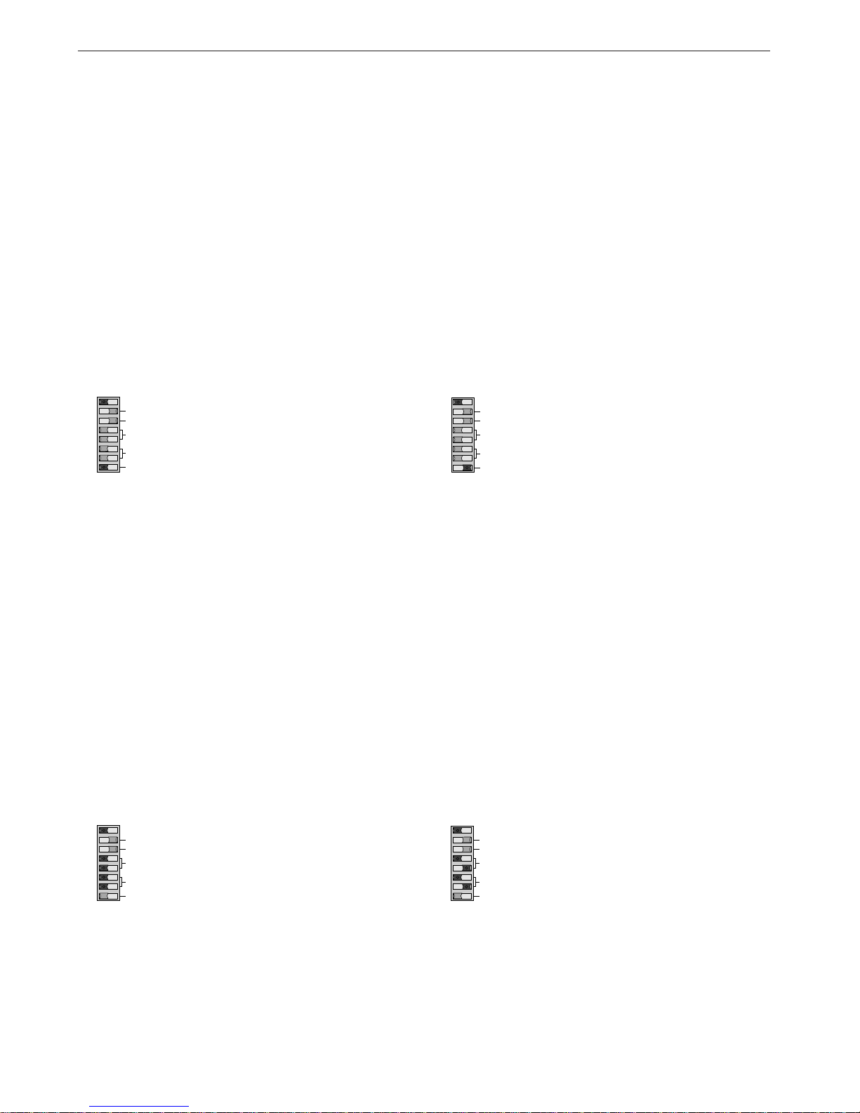
4.4.2 Setting the operating mode
Attention! The following details only apply for the
S7 default position (S7 = 0)!
The DIL switch S0 is used to set the operating mode of
the electrical port CH1.
The DIL switches S1 and S2 are used to set the operating mode of the optical port CH2.
The DIL switches S3 and S4 are used to set the operating mode of the optical port CH3.
S3 and S4 do not have a function on OZD Profi 12M …
with only one optical interface.
4.4.2.1 Setting the operating mode of the
electrical port (CH1)
Operating mode ”Electrical Port with segment
monitoring“
CH1 is activated in this operating
mode if S0 is in Position 0.
Operating mode ”Electrical Port without segment
monitoring“
CH1 is activated in this operating
mode if S0 is in Position 1.
Please note that this operating
mode should only be set in the star
segment of the star topology.
01
S 6
S 7
S 1
S 2
S 4
S 5
S 3
CH 3
CH 2
CH 3
CH 2
S 0
CH 1
01
S 6
S 7
S 1
S 2
S 4
S 5
S 3
CH 3
CH 2
CH 3
CH 2
S 0
CH 1
4.4.2.2 Setting the operating mode of the optical
ports (CH2, CH3)
The operating mode can be set individually for each optical
port. Combinations of the operating modes "Line with
optical fiber link monitoring" and "Line without optical
fiber link monitoring" are also possible.
Note that the operating mode of the two optical ports
which are connected by the fiber line must always have
the same settings!
The operating mode "Redundant optical ring" must
always be set at both of the optical ports.
Operating mode ”Line with optical fiber link
monitoring and segmentation“
CH3 is activated in this operating mode
if S3 and S4 are in Position 0.
CH2 is activated in this operating mode
if S1 and S2 are in Position 0.
Operating mode ”Line without optical fiber link
monitoring“
CH3 is activated in this operating
mode if S3 is in Position 1 and S4
is in Position 0.
CH2 is activated in this operating
mode if S1 is in Position 1 and S2
is in Position 0.
01
S 6
S 7
S 1
S 2
S 4
S 5
S 3
CH 3
CH 2
CH 3
CH 2
S 0
CH 1
01
S 6
S 7
S 1
S 2
S 4
S 5
S 3
CH 3
CH 2
CH 3
CH 2
S 0
CH 1
Page 19

4.4 Setting compatibility, operating mode and transmitting power
19
4 Setting Up
Version 2.4 04/07
Operating mode ”Redundant optical ring“
CH3 is activated in this operating mode
if S3 and S4 are in Position 1.
CH2 is activated in this operating mode
if S1 and S2 are in Position 1.
Note: This operating mode must always be set at both of
the optical ports of a module.
01
S 6
S 7
S 1
S 2
S 4
S 5
S 3
CH 3
CH 2
CH 3
CH 2
S 0
CH 1
4.4.3 Reducing the optical transmitting
power on theOZD Profi 12M P11
and OZD Profi 12M P12
Attention! The following details only apply for the
S7 default position (S7 = 0)!
The OZD Profi 12M P11 and OZD Profi 12M P12 have
a high level of optical transmitting power. Optical overloading may result if these modules are connected with
non-OZD Profi devices using plastic optical fiber cables,
particularly if short cable lengths are used.
In this case the optical transmitting power can be
reduced.
The DIL switch S5 is used to set the transmitting power
of CH2.
The DIL switch S6 is used to set the transmitting power
of CH3.
S6 does not have a function on the OZD Profi 12M P11.
Leave S6 in Position 1 (default) if the
optical fiber link to CH3 functions
correctly in this position.
Leave S5 in Position 1 (default) if the
optical fiber link to CH2 functions
correctly in this position.
Switch S6 to Position 0 (reduced)
if overloading is detected at a nonOZD Profi device when using plastic
optical fiber cables to CH3.
Switch S5 to Position 0 (reduced) if
overloading is detected at a non-OZD
Profi device when using plastic optical
fiber cables to CH2.
01
S 6
S 7
S 1
S 2
S 4
S 5
S 3
CH 3
CH 2
CH 3
CH 2
S 0
CH 1
01
S 6
S 7
S 1
S 0
S 2
S 4
S 5
S 3
CH 3
CH 2
CH 3
CH 1
CH 2
Note:
The DIL switches S5 and S6 on the OZD Profi 12M … for
glass optical fiber cables do not have a function (the
optical transmitting power cannot be reduced).
The transmitting power default setting (S5 or S6 in
Position 1) must be set when using PCF fibers.
Page 20

4 Setting Up 4.5 Installation
20
Version 2.4 04/07
Interference suppression of switched inductances
䡲 Suppressing switched inductances with fuses:
Switching inductances, e.g. in relays and fans,
generates interference voltages which are many
times higher than the switched operating voltage.
These interference voltages can affect electronic
devices.
The interference voltages of inductances must be
limited at their source of emission by means of
fuses (by connecting diodes or RC elements). Only
use interference suppressors which are intended
for the used relays and fans.
䡲 Cabinet lighting:
Use filament lamps (e.g. LINESTRA lamps) for the
cabinet lighting. Do not use fluorescent lamps
because they generate interference fields. If the
use of fluorescent lamps cannot be avoided, the
interference suppression measures shown in Fig. 6
must be implemented.
4.5.1 Installation guidelines
Electromagnetic compatibility (EMC)
Electromagnetic compatibility (EMC) covers all aspects
regarding the effects of radiated and received electrical,
magnetic, and electromagnetic emissions.
In order to prevent interference in electrical systems,
these effects must be reduced to a minimum.
The structural design and correct connection of bus lines
as well as the interference suppression of switched
inductances play a major role in limiting interference.
4.5 Installation
Shield grid
over lamp
Shielded cable
Metal-encased
switch
Mains filter or
shielded mains cable
Fig. 6: Interference suppression of fluorescent lamps in cabinet
Arrangement of devices and cables
䡲 Reducing interference by providing adequate
space:
A simple yet effective way of reducing interference
is to separate devices and cables causing interference from those affected by interference.
Inductive and capacitive interference injection
decreases by the square of the distance between
the elements concerned. This means that doubling
the distance reduces the interference by a factor of 4.
If the arrangement of the various elements in a
building or in the switch cabinet is taken into consideration at the planning stage, the cost of the
necessary interference suppression measures is
generally very low.
䡲 Please note:
Between an OZD Profi 12M … and a power switching
element (e.g. contactor, relay, temperature regulator,
switch, etc.) a minimum separation of 15 cm is to
be maintained.
This minimum separation is to be measured between the outer edges of the components and in all
directions around an OZD Profi 12M ….
The power supply wires (+24 V DC and ) for the
OZD Profi 12M … must not be laid in the same
cable duct as cables for load circuits.
The wires (+24V DC and ) should be twisted
together.
Page 21

4.5 Installation
21
4 Setting Up
Version 2.4 04/07
Shield connections
Always observe the following points when installing bus
line shielding:
䡲 Secure the shield braid using metal cable clamps.
䡲 The clamps must fully enclose the shield and make
good contact (see Fig. 7).
䡲 Only connect the lines via the copper braid shield,
and not via the aluminum foil shield. One side of the
foil shield is attached to a plastic film to increase its
tearing strength, and is therefore non-conductive!
䡲 The shields of all cables which are routed into a
cabinet from the outside must be clamped at the
point of entry inside the cabinet and connected to
the cabinet ground with a large contact surface
area.
䡲 When removing the cable jackets, it is important to
ensure that the braid shield of the cables is not
damaged. Tin-plated or galvanically stabilized
surfaces are ideal for optimum contacting between
grounding elements. With zinc-plated surfaces,
suitable threaded connections must be provided for
the required contacts. Painted surfaces at the
contact points are unsuitable.
䡲 Shield clamps/contact points should not be used
as strain relief devices. Contact with the shield bus
could otherwise deteriorate or break completely.
䡲 Standard recommendations for the arrangement of
devices and cables:
EN 50174–2 contains recommendations for arranging devices and cables which are aimed at reducing mutual interference to a minimum.
䡲 Using bus line shields:
It is important to observe the following when
shielding bus lines:
䡲 - Use only fully shielded lines. The shields of these
lines must be of sufficient thickness to satisfy the
legal requirements for interference radiated and
interference received.
䡲 - Always attach the shields at both ends of the bus
lines. The legal requirements vis-à-vis interference
radiated and interference received for your system
will only be satisfied if shields are connected at
both ends (CE symbol).
䡲 - Attach the shield for the bus line at the connector
plug housing or at the cable clamps provided.
䡲 - In the case of steady-state operation, it is advisable
to strip the shielded line entirely and connect it
with the shielding bus/protective conductor rail.
Note:
If differences in potential occur between the grounding points, an inadmissibly high compensating
current could flow across the shielding connected at
both ends. Never eliminate this problem by removing
the shielding from the bus line!
The following solution is permissible:
Lay an additional equipotential bonding cable parallel
to the bus line. This additional cable will carry the
shield current.
Fig. 7: Securing shielded lines using cable clamps and tube
clips (schematic diagram)
Page 22

4 Setting Up 4.5 Installation
22
Version 2.4 04/07
4.5.3 Mounting the modules
The OZD Profi 12M … modules can either be mounted
on a 35 mm hat rail in accordance with DIN EN 50022
or directly on to a flat surface.
䊳
Install the device in a location where the climatic and
mechanical limit values defined in the Technical Data
can be complied with.
䊳
Ensure that there is sufficient room to connect the bus
and power supply cabling.
䊳
Connect the optical fiber line before mounting the
module. This is easier than connecting it after the
module has been installed.
䊳
Only mount the module on a low-impedance and
low-induction grounded hat rail or base plate. No
other grounding measures are required.
4.5.2 Connecting the optical lines
䊳
Connect the individual modules using a dual-fiber
optical fiber line with BFOC/2.5 connectors.
䊳
Ensure
– that the end faces of the optical plugs are free of
contamination.
– that respectively one optical input a and one
optical output J are connected to one another
(crossover connection).
The BFOC port sockets which belong to one other
are marked on the bottom of the front plate.
– that the optical plugs on the BFOC socket are
securely attached (bayonet fastener must be
slotted in).
– that, with single-mode optical fiber, the BFOC plug
spike is fully pushed into the optical fiber cable
sockets. If necessary, make sure that the optical
fibers are contacted correctly by gripping the
reinforcing sleeve and pushing the connector into
the socket.
䊳
Ensure that there is sufficient strain relief on the
optical fiber line, and pay attention to the minimum
bend radius.
䊳
Seal BFOC sockets which have not been assigned
using the supplied protective caps (note: an optical
port which has not been assigned should be switched
to the operating mode ”Line without optical fiber link
monitoring“ to avoid a break in the fiber line from
being signaled).
Extraneous ambient light can cause interference in
the network, especially under very bright conditions.
Optical components can be rendered useless if dust
infiltrates them.
䊳
Please note the maximum length of the optical fiber
line and the possible fiber types which are shown in
Table 1, p. 6 and in the Technical Data, p. 33.
䊳
After installing the optical network, check the quality
of the link using the measuring sockets. The measured
values must be within the permissible range, as
shown in Appendix 8.7 ”Measuring sockets“, Diagram
1, p.37.
I
I
J
J
CH 2
CH 3
Fig. 8: View of the bottom of the module with the optical ports
2 and 3 (device with two optical ports).
Page 23
4.5 Installation
23
4 Setting Up
Version 2.4 04/07
Mounting on a hat rail
䊳
Hang the top snap-in hooks of the module into the hat
rail and press the underside onto the rail (as shown in
Fig. 7) until it audibly clicks in.
䊳
To remove the module, pull down on the locking slide.
Mounting on a mounting plate
The modules have three through-holes. This allow it to be
mounted on any flat surface, e.g. on the mounting plate
of a switch cabinet.
䊳
Drill three holes in the mounting plate corresponding
to the drilling template in Fig. 8.
䊳
Secure the modules with machine bolts
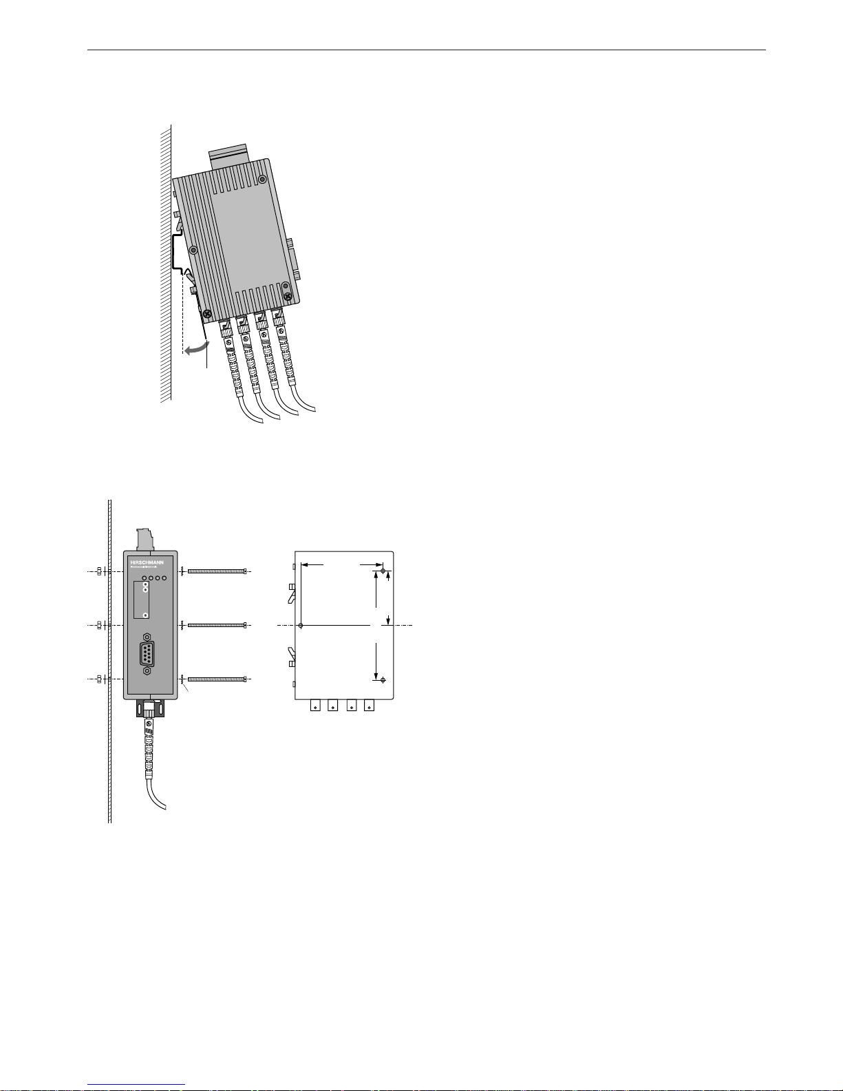
(e.g. M 3 x 40).
䊳
Ensure that there is a reliable electrical connection
between the module housing and the mounting plate.
Place toothed washers under the bolt heads to pierce
the varnish.
Locking slide
Fig. 9: Mounting a module on a standard hat rail
Fig. 10: Mounting a module on a mounting plate
Toothed washer
System
OZD Profi 12M
Receive
Signal
Intensity
CH 1
CH 1
CH 2
CH 2
GND
CH 3
CH 3
61.2 mm
40.6 mm
81.2 mm
Ø 3 mm
Ø 3 mm
Page 24
4 Setting Up 4.5 Installation
24
Version 2.4 04/07
4.5.4 Connecting the electric RS 485 bus
lines
The modules are fitted with an RS 485 electrical port.
This is a 9-pin Sub-D socket with a screw lock (inside
thread UNC 4-40).
The pin assignment complies with the PROFIBUS standard. At Pin 6 there is a short circuit-proof 5 V output for
supplying external pull-up/pull-down resistors.
As opposed to the 24V power supply, the RS 485 bus
lines RxD/TxD–N and RxD/TxD–P are indirect-coupled
(functional separation) within SELV restrictions.
The RS 485 interface is electrically connected to the
housing.
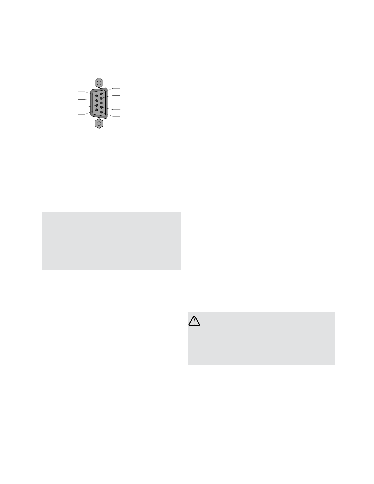
Fig. 11: Electrical port – assignment of Sub-D sockets
9 / n.c.
8 / RxD/TxD –N
7 / n.c.
6 / + 5 V Output
Ground
n.c.
RxD/TxD –P
Ground
PE
Shield
/ 5
/ 4
/ 3
/ 2
/ 1
䊳
Only use shielded and twisted-pair wiring as a RS 485
bus line.
䊳
Use a PROFIBUS bus connector plug to connect the
RS 485 bus segment.
Notes:
- If the module is at the beginning or end of a bus
segment, this connector must have an activated
bus terminal resistor combination.
- Ensure that the bus segment connected to the
RS 485 interface is terminated at both ends.
- Only use a connecting cable which is terminated at
both ends to connect a single device.
䊳
All PROFIBUS bus connector plugs in a network must
be securely screwed onto the RS 485 interfaces.
䊳
Attaching or removing the bus connector plugs,
inadequately attached bus connector plugs or loose
bus wires within the plug can lead to malfunctions in
the optical and electrical networks.
䊳
Attach or remove the RS 485 bus connector plug
quickly and without twisting them.
䊳
Remove the RS 485 bus line from the OZD Profi if a
device is not connected to the other end, or there is
an OZD Profi which has been disconnected from the
power supply. The open line otherwise acts as an
antenna and can cause interference.
䊳
When connecting a RS 485 bus line to the OZD Profi
12M … in an active network, keep to the following
sequence in order to avoid interference:
1. Place the RS 485 bus connector plug onto the
device which is to be connected (e.g. to a programming device) and screw it on tightly.
2. Attach the RS 485 bus connector plug to the
OZD Profi 12M … quickly and without twisting the
connector, and screw it on tightly.
Proceed in the reverse order when removing a device
from the network.
Warning !
Do not connect any bus lines which have been
partially or totally laid outside of buildings. Otherwise
lightning strikes in the vicinity of the cable could destroy
the module. Use optical fiber lines for bus connections
which lead out of a building!!
Page 25

4.5 Installation
25
4 Setting Up
Version 2.4 04/07
4.5.5 Connecting the power supply
The terminal block can be removed from the device to
connect the lines.
䊳
The module should only be supplied with a regulated
safety extra-low voltage in accordance with
IEC 950/EN 60 950/VDE 0805 with a maximum of
+32 VDC (typical +24 VDC). The power source must
comply with the regulations of the NEC, Class 2 in
accordance with UL/CSA approval.
It can be fed in using the 5-pin terminal block on the
top of the module.
䊳
To increase operational safety, the module can be
redundantly supplied via the terminals L2+/+24 VDC*
and M/ .
In the event of a failure of the regular power supply,
the module switches automatically to the redundant
power supply. Load distribution between the individual
alternative supply sources does not take place.
The signaling contact does not signal the failure of
a single 24 V infeed. Both of the infeeds and the
signaling contact must be connected to an input
module for monitoring to take place.
Clips on the terminal block ensure that it is securely
attached to the device, and simultaneously provide
polarity reversal protection.
4.5.6 Connecting the signaling contact
lines
The terminal block can be removed from the device to
connect the lines.
A relay with unconnected contacts as signaling contacts
is fitted to the 5-pin terminal block on the top of the
module. This signals faults and interference in the network and modules. The contact is open if a fault occurs.
This also signals a total loss of power at the module.
Refer to Chapter 5.1 ”LED indicators“ p. 27 for more
details about malfunctions which are signaled by the
signaling contact.
Signaling contact limit values:
– maximum switching voltage 60 VDC; 42 VAC
– maximum switching current 1.0 A
The voltage connected to the relay must be regulated
safety extra-low voltage in accordance with
IEC 950/EN 60 950/ VDE 0805 and must comply with
the regulations of the NEC, Class 2 in accordance with
UL/CSA approval.
L1+ / +24 VDC
F1
M /
F2
L2+ / +24 VDC*
Fig. 12: Operating voltage supply – assignment of 5-pin terminal
block
Fig. 13: Signaling contact - relay with unconnected contacts;
the contact is open if a fault occurs
F1 F2
Page 26

4 Setting Up 4.5 Installation
26
Version 2.4 04/07
4.5.7 Defining the receiving level of the
optical ports
The receiving level of the two optical Ports CH2 and CH 3
can be measured using a conventional voltmeter connected to the measuring sockets. The voltmeter can be
connected and disconnected while the module is in
operation without any interference using 2 mm laboratory
test plugs.
The OZD Profi 12M … is protected against short circuits
at the measuring sockets, although data transmission
may be briefly disrupted.*
With this
– the incoming optical performance can be documented,
e.g. for later measurements (ageing, damage)
– a good/poor check can be carried out (limit value).
Further information can be found in Appendix 8.7
”Measuring sockets“ p.37.
* Only an ungrounded, high-resistance voltmeter may be
used to take measurements.
The reference potential socket may not be connected
to the OZD Profi 12M … housing.
䊳
Pin assignment, 5-pin terminal block: terminals F1
and F2.
䊳
Always ensure that the pins are correctly assigned at
the 5-pin terminal block. Make sure that the connecting leads of the signaling contacts are adequately
insulated, particularly if you are working with voltages
greater than 32 V. Incorrect assignment can lead to
destruction of the module.
Fig. 14: Signaling contact – pin assignment 5-pin terminal block
L1+ / +24 VDC
F1
M /
F2
L2+ / +24 VDC*
System
OZD Profi 12M
Receive
Signal
Intensity
CH 1 CH 2
CH 2
GND
CH 3
CH 3
Measuring sockets
Reference potential
Fig. 15: Location of the measuring sockets
Page 27

5.1 LED Indicators
27
5 LED Indicators and Troubleshooting
Version 2.4 04/07
5 LED Indicators and Troubleshooting
Fig. 16: LED indicators on the front plate
System
OZD Profi 12M
Receive
Signal
Intensity
CH 1 CH 2
CH 2
GND
CH 3
CH 3
LED indicators
Possible causes
– The transmission rate has been recognized and the power supply is in order
– Power supply has failed (total failure*)
– Power supply connected incorrectly
– Module defective
Transmission rate has not yet been recognized
– No transmitting bus subscriber present
– No connection to a partner module sending frames
– Send and receive optical fibers have been transposed
– Transmission rate does not correspond to the PROFIBUS standard
– Only one active bus subscriber is connected, which is only sending tokens to
itself. The indicator must switch over after a second bus subscriber has been
activated (token frames on their own are not enough to set the transfer rate).
– The connected RS 485 segment is only terminated at one end.
Transmission rate recognized but
– the network slot time could not be determined (network parameter HSA is set
too low, no transmitting bus subscriber present)
– one optical port is set to ”Redundant optical ring“ mode, but not the second
(this operating mode must always be set at both optical ports)
– the slot time of the network configuration is too short
* failure of both power supply sources with redundant infeed
LED Indicator
System
䡲 lights green
䡲 not lit
䡲 flashes red
䡲 flashes red/green
Signaling contact
no signal
signal
no signal
no signal
5.1 LED Indicators
Page 28

5 LED Indicators and Troubleshooting 5.1 LED Indicators
28
Version 2.4 04/07
Possible causes
Signals are being received on the RS 485 bus line
– Bus subscriber is not connected
– Connected bus subscriber is not switched on
– One or both conductors in the RS 485 bus line is broken
Sporadic interference signals because
– the RS 485 bus line being insufficiently shielded
– an open RS 485 bus line, i.e. it is only connected to the module at one end
– the RS 485 segment is not terminated or only terminated at one end
– an RS 485 bus terminal or terminal connector has been plugged in/ pulled out
Permanent interference because
– conductors A and B in the RS 485 bus line have been transposed
– of an RS 485 bus line short circuit
– the send time has been exceeded caused by a bus subscriber in a bus
segment connected to Port 1
– module and another bus subscriber connected via Port 1 are both sending at
the same time (e.g. because an address has been assigned twice, the setting
of the slot time is too low, or during lifting of the segmentation in the optical
line, see Chap. 3.1.1)
– RS 485 driver of the module is defective (e.g. after lightning strike)
PROFIBUS frames are being received at the optical port
Operating mode ”Line with optical fiber link monitoring“ and
”Redundant optical ring“
Transmission rate has not yet been recognized – LED ”System“ flashes red
– No transmitting bus subscriber present
– Send and receive optical fibers have been transposed
– No partner module connected or partner module is not switched on
– Connected partner module is defective
Transmission rate has been recognized - LED ”System“ flashes green
– If the operating mode ”Redundant optical ring“ has been set, the optical port
works as a stand-by port. There is no malfunction in the OZD Profi or the
optical fiber.
– If one of the operating modes ”Line with optical fiber link monitoring …“ has
been set, no PROFIBUS frames are received at the optical port. There is no
malfunction in the OZD Profi or the optical fiber.
Transmission rate has been recognized – LED ”System“ lights green or
flashes red/green
– No transmitting bus subscriber present (optical fiber connection is OK)
– Send and receive optical fibers have been transposed
– No partner module connected or partner module is not switched on
– Connected partner module is defective
– Send time of connected partner module has been exceeded
– An optical fiber line is broken
– Optical fiber link to partner module is too long
– Loose connection in an optical fiber connector
– Optical fiber in the optical fiber connector is loose
– When using a redundant optical ring: if a fault in the optical fiber has been
corrected but the port LEDs on both of the OZD Profi concerned still light
red, check whether parameter HSA has been set as described the in Chap. 3.3.
– Fault occurs periodically (see above)
– Loose connection in an optical fiber connector
– Optical fiber in the optical fiber connector is loose
– Only one active bus subscriber is connected, which only sends tokens to
itself. A fault should not be signaled as soon as a second subscriber is
activated.
Operating mode ”Line without optical fiber link monitoring“
Signals are received at the optical port.
– No transmitting bus subscriber present
– Send and receive optical fibers have been transposed
– No partner module connected or partner module is not switched on
– Connected partner module is defective
LED Indicator
CH1
䡲 lights yellow
electric
䡲
not lit
䡲 flashes/lights red
CH2, CH3
䡲 lights yellow
optical
䡲 not lit
䡲 flashes yellow
䡲 lights red
䡲 flashes red/ yellow
䡲 lights yellow
䡲 not lit
Signaling contact
no signal
no signal
signal
no signal
no signal
no signal
no signal
signal
signal
no signal
no signal
Table 2: What the LED indicators and signaling contacts mean
Page 29

5.2 Troubleshooting
29
5 LED Indicators and Troubleshooting
Version 2.4 04/07
This chapter helps you to localize faults after they have
been indicated (by LEDs or signal contacts).
Please also refer to the description of the LED indicators
in 5.1, p. 27.
5.2 Troubleshooting
Fault indicated on the system LED
See description of the LED indicators in 5.1, p. 27.
Fault indicated on CH1
Check the following:
䊳
the DIL switch S0 is in Position 1 if the OZD Profi
connected to the electrical star segment of a star
topology (see Chap. 3.2 ”Star topology“, p. 12).
䊳
the fault is still displayed after removal of the RS485
connector.
Still displayed: Device is defective*.
Replace the OZD Profi.
No longer displayed: The fault lies in the RS485 bus
segment.
Check
– all RS485 connectors as described in 4.5.4
”Connecting the electrical RS 485 bus lines“,
p. 24
– the structure and shielding of the RS485 bus
segment
– the RS485 bus segment using a PROFIBUS bus
monitor
– the configuration of all bus subscribers.
* This is not the case if the monomaster of a PROFIBUS network is connected to the RS485 bus segment
which is to be examined. Replace the OZD Profi concerned with another OZD Profi from the network, and
then carry out the test described above.
If the OZD Profi still malfunctions when connected
elsewhere, the device is defective. Replace the OZD
Profi.
If the OZD Profi does not malfunction elsewhere, the
fault lies in the RS485 bus segment.
Carry out the measures described above.
Fault indicated on CH2 / CH3
1. Check the following:
䊳
optically only modules of the same type are connected together (see 3, ”Network topologies“, p. 9)
䊳
the optical fiber has been approved for the module
type being used, and that it does not exceed the permitted length (see Table 1, p. 6)
䊳
the optical ports, which are connected via optical
fibers, have been set to the same operating mode
(see 4.4, ”Setting compatibility, operating mode and
transmitting power“, p. 17)
䊳
the settings given in 4.5.2, ”Connecting the optical
lines“ (p. 22) have been observed when connecting
and laying the optical bus lines.
2. Define the optical receiving level (see 4.5.7 ”Defining
the receiving level of the optical ports“, p. 26 and
8.7 ”Measuring sockets“, p. 37):
– Level is in the range ”Function is not guaranteed“.
䊳
Check the optical fiber absorption using an optical level measuring device.
too high: replace the optical fiber
in valid one of the two OZD Profi of the disturbed
range: optical fiber segments is defective.
First replace the other OZD Profi of the
disturbed optical fiber segments (i.e.
the OZD Profi, which supplies the send
signal for the measurement described
above). If the fault still persists, replace
the other OZD Profi instead.
– Level is in the range ”Optical system reserves
reduced“ or ”Normal mode“.
䊳
As described above, check the optical receiving
level of the other OZD Profi in the disturbed optical
fiber segment at the appropriate port.
Page 30

5 LED Indicators and Troubleshooting 5.2 Troubleshooting
30
Version 2.4 04/07
– The levels at both OZD Profi of the disturbed
optical fiber segments are in the range ”Optical
system reserves reduced“ or ”Normal mode": one
of the two OZD Profi in the disturbed optical fiber
segments is defective.
䊳
First replace one of the OZD Profi in the disturbed optical fiber segment. If the fault still
persists, replace the other OZD Profi instead.
Page 31

6.1 Configuration of redundant optical rings
31
6 Configuration
Version 2.4 04/07
6 Configuration
During configuration, the PROFIBUS network parameter
"Slot time" must be adapted to the network coverage,
network topology and the data rate due to frame delays
caused by lines and network components, as well as by
monitoring mechanisms in the network components.
6.1 Configuration of redundant optical rings
The following configuration conditions must be fulfilled in
the redundant optical ring (for details see Chap. 3.3
”Redundant optical ring“, p.13):
䡲 (1) Configuration of a non-existent bus subscriber
䡲 (2) Increasing the retry value to at least 3
䡲 (3) Checking and adjusting the slot time
Use the user-specific profile of the configuration tool to
set the parameters under (2) and (3).
Calculate the slot time with the following equation:
Slot time = a + (b.Length OF) + (c.Number
OZD
)
䡲 ”Slot time“ is the monitoring period in bit times
䡲 ”Length OF“ is the sum of all the optical fiber
lines (segment lengths) in the network.
The length must be given in km!
䡲 ”Number
OZD
“ is the number of OZD Profi 12M …
in the network.
The factors a, b and c are dependent on the transmission
rate and are listed in the tables below.
Data rate a b c
12 MBit/s
1)
1651 240 28
6 MBit/s
1)
951 120 24
3 MBit/s
1)
551 60 24
1.5 MBit/s 351 30 24
500 kBit/s 251 10 24
187.5 kBit/s 171 3.75 24
93.75 kBit/s 171 1.875 24
45.45 kBit/s 851 0.909 24
19.2 kBit/s 171 0.384 24
9.6 kBit/s 171 0.192 24
Table 3a: Constants for calculating the slot time at DP standard
(redundant optical ring)
Data rate a b c
12 MBit/s
1)
1651 240 28
6 MBit/s
1)
951 120 24
3 MBit/s
1)
551 60 24
1.5 MBit/s 2011 30 24
500 kBit/s 771 10 24
187.5 kBit/s 771 3.75 24
93.75 kBit/s 451 1.875 24
45.45 kBit/s 851 0.909 24
19.2 kBit/s 181 0.384 24
9.6 kBit/s 171 0.192 24
Table 3b: Constants for calculating the slot time at DP/FMS
(”universal“) and DP with S595U (redundant optical
ring)
1)
see p. 32
Page 32

6 Configuration 6.1 Configuration of redundant optical rings
32
Version 2.4 04/07
The calculation of the slot time only takes into consideration the optical network and the connection of bus subscribers to the OZD Profi via an RS 485 bus segment
with a respctive length of max. 20 m. Longer RS 485 bus
segments must be allowed for by adding them to the
LengthOF.
Note:
When the slot time is configured with a too small value
the OZD Profi 12M … will, through it’s fault function and
fault indications, indicate such. The System-LED will
blink red/green.
1)
Using the OZD Profi 12M G11-1300 (EEC) and … G121300 (EEC) at data rates of 12 MBit/s, 6 MBit/s, 3 MBit/s
and 1.5 MBit/s the minimum slot times according to the
following table must be met.
Data rate Minimum slot time
12 MBit/s 3800 t
Bit
6 MBit/s 2000 t
Bit
3 MBit/s 1000 t
Bit
1.5 MBit/s 530 t
Bit
Table 4: Minimum slot time on OZD Profi 12M G11-1300
(EEC) and OZD Profi 12M G12-1300 (EEC)
Use the values from Table 4 if the calculated slot time
is smaller than the minimum slot time indicated in the
table.
Page 33

33
7 Technical Data
Version 2.4 04/07
OZD Profi 12M … P11 G11 G11-1300
P12 G12 G12-1300
G12-EEC G12-1300 EEC
Voltage/power supply
Operating voltage 18 V to 32 VDC, typ. 24 VDC, (redundant inputs uncoupled),
safety extra-low voltage, indirect-coupled
Current consumption max. 200 mA
Output voltage/current for terminal 5 V + 5%, – 10%/90 mA; short circuit-proof
resistors (Pin 6 Sub-D socket)
Signaling contact
Maximum switch voltage 60 VDC; 42 VAC (safety extra-low voltage)
Maximum switch current 1.0 A
Signal transmission
Transmission rate 9.6; 19.2; 45.45; 93.75; 187.5; 500 kBit/s
1.5; 3; 6; 12 Mbit/s
Setting transmission rate automatic
Bit error rate < 10
-9
Signal processing time (any input/output) <_ 6.5 t
Bit
Retimer
Input Port 1 to 3
Signal distortion ± 30 %
Bit length ± 0.12 %
Output Port 1 to 3
Mean bit length ± 0.01 %
Safety
VDE regulation VDE 0805 = EN 60950 und IEC 60950
UL/CSA approval UL 1950/CSA 950
FM approval CLASS I: DIV 2 GROUP A; B; C und D; T5
Ex approval EEx nC [L] IIC T5; TA: 0 °C … 60 °C
Electrical port
Input/output signal RS 485 level
Input dielectric strength – 10 V to + 15 V
PIN assignment, port 1 in accordance with EN 50170 Part 1
Optical ports
Wavelength 660 nm 860 nm 1310 nm
Launchable optical power
– in glass fiber E 10/125 – – –19 dBm
– in glass fiber G 50/125 – –15 dBm –17 dBm
– in glass fiber G 62.5/125 – –13 dBm –17 dBm
– in PCF fiber S 200/230
transmitting power ”Reduced“ – – –
transmitting power ”Default“ – 17 dBm – 10 dBm –
– in plastic fiber S 980/1000
transmitting power ”Reduced“ –10 dBm – –
transmitting power ”Default“ –5 dBm – –
Receiver sensitivity – 25 dBm – 28 dBm – 29 dBm
Receiver overload limit – 3 dBm – 3 dBm – 3 dBm
7 Technical Data
Page 34

7 Technical Data
34
Version 2.4 04/07
OZD Profi 12M … P11 G11 G11-1300
P12 G12 G12-1300
G12-EEC G12-1300 EEC
Transmission distance
– with glass fiber E 10/125 – – 0 - 15 000 m
2)
(0.5 dB/km)
– with glass fiber G 50/125 – 0 - 3 000 m
2)
0 - 10 000 m
(860 nm: 3.0 dB/km; 1310 nm: 1.0 dB/km)
– with glass fiber G 62.5/125 – 0 - 3 000 m
2)
0 - 10 000 m
(860 nm: 3.5 dB/km; 1310 nm: 1.0 dB/km)
– with PCF fiber S 200/230
Transmitting power ”Reduced“ – – –
Transmitting power ”Default“ 0 - 400 m
2)
0 - 1000 m
2)
–
(660 nm: 10.0 dB/km; 860 nm: 8.0 dB/km)
– with plastic fiber S 980/1000
Transmitting power ”Reduced“ 0 - 50 m – –
Transmitting power ”Default“ 0 - 80 m – –
(0.2 dB/m)
Connector BFOC/2.5
Electromagnetic compatibility (EMC)
Interference emissions Limit class B (EN 55022)
Interference immunity against static charges At shielded socket and housing parts: ±8 kV contact discharge
(EN 61000-4-2)
Immunity against high-frequency interference – 10 V/m at 80% amplitude modulation with 1 kHz,
– 80 MHz - 1 GHz (EN 61000-4-3)
– 10 V/m at 50% on-period at 900 MHz (ENV 50204)
– 10 V/m at 80% amplitude modulation with 1 kHz,
– 10 kHz - 80 MHz
Immunity against line-conducted disturbance On power supply lines and shielded
(Burst) RS 485 bus lines: ±2 kV (EN 61000-4-4)
Immunity against line-conducted disturbance – On power supply lines: ±1 kV symmetrical
(Surge) – On shielded RS 485 bus lines: ±2 kV asymmetrical
– (EN 61000-4-5)
Climatic ambient conditions
Ambient temperature (IEC 68-2-1, IEC 68-2-2) 0 °C to +60 °C
–20 °C to +60 °C at OZD … G12-EEC
1)
(IEC 68-2-1, IEC 68-2-2)
Storage temperature –40 °C to +70 °C (IEC 68-2-14)
Relative humidity (IEC 68-2-30) <95 %, non-condensing
100 %, condensing at OZD … G12-EEC
1)
(IEC 68-2-30)
Mechanical ambient conditions
Vibration (during operation) 10 to 58 Hz, 0.075 mm displacement;
58 to 150 Hz, 10 m/s
2
(1 g) acceleration (IEC 68–2–6)
Vibration (during transport) 5 to 9 Hz, 3.5 mm displacement;
9 to 500 Hz, 10 m/s
2
(1 g) acceleration
Protection class IP 40
Dimensions (W x H x D) 40 x 111 x 73.5 mm
Housing material Die-cast zinc
Weight approx. 500 g
1) The OZD Profi 12M G12 can also be supplied in a special design for more severe environmental conditions. This variant is designated the
OZD Profi 12M G12-EEC.
The DIL switches on the OZD Profi 12M G12-EEC may also only be operated at ambient temperatures between 0°C and + 60°C.
2) The specified distance allowed between two OZD Profi must not be exceeded regardeless of the optical power budget.
The module does not contain any silicon.
Page 35

8.1 FCC conformity
35
8 Appendix
Version 2.4 04/07
8.1 FCC conformity
Note: This equipment has been tested and found to
comply with the limits for a Class B digital device,
pursuant to part 15 of the FCC Rules.
These limits are designed to provide reasonable protection against harmful interference in a residential installation.
This equipment generates, uses and can radiate radio
frequency energy and, if not installed and used in accordance with the instructions, may cause harmful interference to radio communications. However, there is no
guarantee that interference will not occur in a particular
installation. If this equipment does cause harmful inter-
ference to radio or television reception, which can be
determined by turning the equipment off and on, the user
is encouraged to try to correct the interference by one or
more of the following measures:
- Reorient or relocate the receiving antenna.
- Increase the separation between the equipment and
receiver.
- Connect the equipment into an outlet on a circuit
different from that to which the receiver is connected.
-Consult the dealer or an experienced radio/TV technician
for help.
8 Appendix
8.2 FM approval
FM 3611
9
INDUSTRIAL CONTROL EQUIPMENT
FOR USE IN
HAZARDOUS LOCATIONS
CLASS I: DIV. 2
GROUP A; B; C AND D
T5: T
A
: O °C … 60 °C
8.3 Ex approval
8
II 3 G
EEx nC [L] IIC T5
KEMA 00 ATEX 1141 X
8.4 UL/CSA approval
1
UL 1950/CSA 950
File Nr. E 168 643
Page 36

8 Appendix 8.5 C-Tick
36
Version 2.4 04/07
8.6 Literature notes
– Wrobel, Christoph (Herausgeber):
„Optische Übertragungstechnik in industrieller
Praxis“,
Hüthig Buch Verlag GmbH, Heidelberg 1994
– G. Mahlke, P Gössig:
„Lichtwellenleiterkabel: Grundlagen, Kabeltechnik“
3. Auflage, Berlin 1992
– Technical directive:
„Optische Übertragungstechnik für Profibus“,
Publisher Profibus-Nutzerorganisation e. V.,
Karlsruhe
– EN 50170-1-2 1996:
„General Purpose Field Communication System“,
Volume 2 „Physical Layer Spezification and Service
Definition“
– DIN 19245:
„Messen, Steuern, Regeln; PROFIBUS Teil 1;
Process Field Bus; Übertragungstechnik, …“
„Messen, Steuern, Regeln; PROFIBUS Teil 3;
Process Field Bus; Dezentrale Peripherie (DP)“
– EIA Standard RS–485 (April 1983):
„Standard for electrical characteristics of generators“
8.7 List of abbreviations
BFOC Bajonet Fiber Optic Connector
DIN Deutsche Industrie Norm
(German Industrial Standard)
EEC Extended Environmental Conditions
EIA Electronic Industries Association
EN Europäische Norm (European Standard)
EMC Electromagnetic Compatibility
HCS™ Hard Polymer Cladded Silica Fiber
(registered trademark of Ensign-Bickford)
IEC International Electrotechnical
Commission
LED Light Emitting Diode
PCF Polymer Cladded Fiber
(equal to HCS™)
PNO PROFIBUS Nutzer Organisation
(PROFIBUS User Organization)
SELV Secure Electrical Low Voltage
UL Underwriter Laboratories
VDE Verein Deutscher Elektroingenieure
(Association of German Electrical Engineers)
8.5 C-Tick
Australia / New Zealand
N13320
This product meets the requirements of
the AS/NZS 3548 standard.
Page 37

8.7 Measuring sockets
37
8 Appendix
Version 2.4 04/07
8.8 Measuring sockets
Normal operation
0 100 200 300 400 500 600 700 800 900
Output voltage [mV]
Signal
quality
good
critical
poor
Reduced optical system reserves
Function not guaranteed
Diagram 1: Assignment of measured output voltage to signal quality.
Notes:
In order to attain a valid reading, it is necessary for the
partner OZD Profi at the other end of the optical fiber
to send regular PROFIBUS frames. This can be seen on
the LED display of the partner OZD Profi (see 5, ”LED
Indicators and Troubleshooting“, p. 27).
The output voltage at the measuring sockets is subject to
many influencing factors, such as:
䡲 the strength of the transmitting power of the
partner OZD Profi
䡲 the ambient temperature of the optical sender
and receiver
䡲 attenuation of the transmitting link
䡲 the transfer rates being used
The measuring sockets are therefore not intended as a
substitute for a calibrated level measuring device with a
calibrated light source.
The readings taken should only serve to classify the
optical signal being received in the 3 classes
䡲 good (normal operation)
䡲 critical (reduced optical system reserves)
䡲 poor (function not guaranteed)
Measurements must be taken with a conventional
ungrounded and high-resistance voltmeter. A connection
to the OZD Profi 12M … housing is not permitted either
from the measuring sockets or the reference potential.
Page 38

9 Application Support
38
Version 2.4 04/07
9 Application Support
Contact address for technical support
Hirschmann Automation and Control GmbH
Stuttgarter Strasse 45 - 51
72654 Neckartenzlingen
Germany/Allemagne
Tel.: ++49 / 1805/ 14-1538
Fax: ++49 / 7127/ 14-1551
E-Mail: [email protected]
Internet: http://www.hirschmann.com
Page 39

Hirschmann Automation and Control GmbH
Stuttgarter Strasse 45 - 51
72654 Neckartenzlingen
Germany/Allemagne
Tel.: +49 / 1805/ 14-1538
Fax: +49 / 7127/ 14-1551
E-Mail: [email protected]
Internet: http://www.hirschmann.com
039 629-001-E-04-0407 Printed in Germany
 Loading...