

Installation OZD Genius...
Release 01 09/2017
Technical Support
https://hirschmann-support.belden.eu.com
User Manual
Installation
Fiberoptic Repeater
OZD Genius...

The naming of copyrighted trademarks in this manual, even when not specially indicated, should
not be taken to mean that these names may be considered as free in the sense of the trademark
and tradename protection law and hence that they may be freely used by anyone.
© 2017 Hirschmann Automation and Control GmbH
Manuals and software are protected by copyright. All rights reserved. The copying, reproduction,
translation, conversion into any electronic medium or machine scannable form is not permitted,
either in whole or in part. An exception is the preparation of a backup copy of the software for
your own use.
The performance features described here are binding only if they have been expressly agreed
when the contract was made. This document was produced by Hirschmann Automation and
Control GmbH according to the best of the company's knowledge. Hirschmann reserves the right
to change the contents of this document without prior notice. Hirschmann can give no guarantee
in respect of the correctness or accuracy of the information in this document.
Hirschmann can accept no responsibility for damages, resulting from the use of the network
components or the associated operating software. In addition, we refer to the conditions of use
specified in the license contract.
You can get the latest version of this manual on the Internet at the Hirschmann product site
(www.hirschmann.com).
Hirschmann Automation and Control GmbH
Stuttgarter Str. 45-51
72654 Neckartenzlingen
Germany
Installation OZD Genius... 14.09.2017

Installation OZD Genius...
Release 01 09/2017
3
Contents
Safety instructions 5
About this manual 10
Key 11
1 Description 12
1.1 General description 12
1.2 Device view 16
1.3 Display elements 17
2 Network Topologies 19
2.1 Line topology without redundancy 19
2.2 Redundant optical ring 20
3 Installation 22
3.1 Checking the package contents 22
3.2 Installing and grounding the device 23
3.2.1 Installing the device onto the DIN rail 23
3.2.2 Mounting the device on a mounting plate 24
3.2.3 Grounding the device 24
3.3 Connecting the optic bus cables 25
3.4 Connecting the electric bus cables 26
3.5 Connecting the power supply 27
3.6 Connecting the signal contact 28
3.7 Setting the data rate 29
3.8 Setting the optical transmitting power 30
3.9 Network range for line and ring topologies 30
4 Disassembly 32

4
Installation OZD Genius...
Release 01 09/2017
5 Technical data 33
6 Scope of delivery, order numbers and
accessories 36
7 Underlying technical standards 37
8 Troubleshooting 38
A Further support 39

Installation OZD Genius...
Release 01 09/2017
5
Safety instructions
General safety instructions
You operate this device with electricity. Improper usage of the device
entails the risk of physical injury or significant property damage. The
proper and safe operation of this device depends on proper handling
during transportation, proper storage and installation, and careful
operation and maintenance procedures.
Before connecting any cable, read this document, and the safety
instructions and warnings.
Operate the device with undamaged components exclusively.
The device is free of any service components. In case of a damaged
or malfunctioning the device, turn off the supply voltage and return the
device to Hirschmann for inspection.
Qualification requirements for personnel
Only allow qualified personnel to work on the device.
Qualified personnel have the following characteristics:
Qualified personnel are properly trained. Training as well as practical
knowledge and experience make up their qualifications. This is the
prerequisite for grounding and labeling circuits, devices, and systems
in accordance with current standards in safety technology.
Qualified personnel are aware of the dangers that exist in their work.
Qualified personnel are familiar with appropriate measures against
these hazards in order to reduce the risk for themselves and others.
Qualified personnel receive training on a regular basis.
WARNING
UNCONTROLLED MACHINE ACTIONS
To avoid uncontrolled machine actions caused by data loss, configure all
the data transmission devices individually.
Before you start any machine which is controlled via data transmission, be
sure to complete the configuration of all data transmission devices.
Failure to follow these instructions can result in death, serious injury,
or equipment damage.

6
Installation OZD Genius...
Release 01 09/2017
Certified usage
Use the product only for the application cases described in the
Hirschmann product information, including this manual.
Operate the product only according to the technical specifications.
See “Technical data” on page 33.
Connect to the product only components suitable for the requirements
of the specific application case.
Device casing
Only technicians authorized by the manufacturer are permitted to open
the housing.
National and international safety regulations
Verify that the electrical installation meets local or nationally applicable
safety regulations.
Grounding the device
Functional grounding the device is by means of a separate connection on
the device.
Ground the device before connecting any other cables.
Disconnect the grounding only after disconnecting all other cables.
Ground the device via the ground screw.
Requirements for connecting electrical wires
Before connecting the electrical wires, always verify that the
requirements listed are complied with.
All of the following requirements are complied with:
The electrical wires are voltage-free.
The cables used are permitted for the temperature range of the application case.
Table 1: General requirements for connecting electrical wires
All of the following requirements are complied with:
The voltage connected complies with the requirements for a safety extra-low voltage
(SELV) as per IEC/EN 60950-1.
The connected voltage is limited by a current limitation device or a fuse.
Observe the electrical threshold values for the signal contact.
See “General technical data” on page 33.
Table 2: Requirements for connecting the signal contact

Installation OZD Genius...
Release 01 09/2017
7
Supply voltage
Only switch on the device when the housing is closed.
Requirements
All of the following requirements are complied with:
The supply voltage corresponds to the voltage specified on the type plate of the device.
The power supply conforms to overvoltage category I or II.
The power supply has an easily accessible disconnecting device (e.g., a switch or a plug).
This disconnecting device is clearly identified. So in the case of an emergency, it is clear
which disconnecting device belongs to which power supply cable.
The cross-section of the ground conductor is the same size as or bigger than the cross-
section of the power supply cables.
Relevant for North America:
The power supply cables are suitable for ambient air temperatures of at least 167 °F
(75 °C). The power supply cable wires are made of copper.
The wire diameter of the power supply cable is at least 0.75 mm² (North America: AWG18) on
the supply voltage input.
The following requirements are alternatively complied with:
Alternative 1 The power supply complies with the requirements for a limited
power source (LPS) as per EN 60950-1.
Alternative 2 Relevant for North America:
The power supply complies with the requirements according to
NEC Class 2.
Alternative 3 All of the following requirements are complied with:
The power supply complies with the requirements for a safety
extra-low voltage (SELV) as per IEC/EN 60950-1.
A fuse suitable for DC voltage is located in the plus conductor
of the power supply.
The minus conductor is on ground potential. Otherwise, a fuse
is also located in the minus conductor.
Regarding the properties of this fuse:
See 33 “General technical data”.
Table 3: Requirements for connecting the supply voltage

8
Installation OZD Genius...
Release 01 09/2017
CE marking
The labeled devices comply with the regulations contained in the following
European directive(s):
2014/30/EU (EMC)
Directive of the European Parliament and of the Council on the
harmonisation of the laws of the Member States relating to
electromagnetic compatibility.
2011/65/EU (RoHS)
Directive of the European Parliament and of the Council on the restriction
of the use of certain hazardous substances in electrical and electronic
equipment.
In accordance with the above-named EU directive(s), the EU conformity
declaration will be at the disposal of the relevant authorities at the
following address:
Hirschmann Automation and Control GmbH
Stuttgarter Str. 45-51
72654 Neckartenzlingen
Germany
The product can be used in the industrial sector.
Interference immunity: EN 61000-6-2
Emitted interference: EN 55032
Reliability: EN 60950-1
You find more information on technical standards here:
“Technical data” on page 33
Warning! This is a class A device. This device can cause interference in
living areas, and in this case the operator may be required to take
appropriate measures.
Note: The assembly guidelines provided in these instructions must be
strictly adhered to in order to observe the EMC threshold values.
LED or laser components
LED or LASER components according to IEC 60825-1 (2014):
CLASS 1 LASER PRODUCT
CLASS 1 LED PRODUCT

Installation OZD Genius...
Release 01 09/2017
9
FCC note:
This device complies with part 15 of the FCC rules. Operation is subject
to the following two conditions: (1) this device may not cause harmful
interference; (2) this device must accept any interference received,
including interference that may cause undesired operation.
Appropriate testing has established that this device fulfills the
requirements of a class A digital device in line with part 15 of the FCC
regulations.
These requirements are designed to provide sufficient protection against
interference when the device is being used in a business environment.
The device creates and uses high frequencies and can also radiate these
frequencies. If it is not installed and used in accordance with this
operating manual, it can cause radio transmission interference. The use
of this device in a residential area can also cause interference, and in this
case the user is obliged to cover the costs of removing the interference.
Recycling note
After usage, this device must be disposed of properly as electronic waste,
in accordance with the current disposal regulations of your county, state,
and country.

10
Installation OZD Genius...
Release 01 09/2017
About this manual
The “Installation” user manual contains a device description, safety
instructions, a description of the display, and the other information that you
need to install the device.

Installation OZD Genius...
Release 01 09/2017
11
Key
The symbols used in this manual have the following meanings:
Listing
Work step
Subheading

12
Installation OZD Genius...
Release 01 09/2017
1 Description
1.1 General description
The Fiberoptic Repeater OZD Genius... is designed for use in optical Genius
bus field bus networks. It allows conversions of electrical Genius bus
interfaces into optical Genius bus interfaces and vice versa.
The repeaters can be integrated in existing Genius bus field bus networks.
OZD Genius... repeaters can also be used to configure a complete Genius
bus field bus network with the line or ring topology.
Apart from setting the data rate, no other adjustments have to be made
during set-up.
Device casing
The device is supplied in a metal housing. You have the option of
mounting the device onto the DIN rail or to the mounting plate.
Glass fiber technology
The use of glass fiber transmission technology enables a very large
transmission range and ensures optimal protection from EMC effects on
the transmission path and – due to the potential separation – on the
Repeater itself.
Data rate
The fiber-optic repeater OZD Genius G12… supports the data rates
153.6 kBaud (standard and extended),76.8 kBaud and 38.4 kBaud.
Redundancy
Redundant optical signal transmission ensures a very high level of
transmission reliability. The redundant operating power supply can further
improve the operating reliability.
Installation OZD Genius...
Release 01 09/2017
13
Port
The repeater has three mutually independent ports (channels), each of
which consists of a transmitter and receiver. The electrical port is a 4-pin
connector, the optical ports are BFOC/2.5 (ST ®) sockets.
CH2
CH3
CH1

14
Installation OZD Genius...
Release 01 09/2017
Power supply
The power supply is 24 V direct current. To improve the operating safety,
a redundant operating power supply consisting of two separate sources
can be used. For this purpose, you must connect the two supply voltages
to two different terminals of the 8-pin screw-type terminal block. There is
no load distribution between the sources. There is no load distribution
between the sources. With redundant supply, the power supply unit with
the higher output voltage must supply the repeater alone.
Signal contact
A signal contact (relay with unconnected contacts) is used to signal
various disruptions in the repeaters. The signal contact is also connected
to the 8-pin screw type terminal block.
L1+
F1
0V
F2
L2+
Ua2
GND
Ua1
+24V
Fault
+24V
L1+
F1
0V
F2
L2+
Ua2
GND
Ua1
+24V
Fault
+24V

Installation OZD Genius...
Release 01 09/2017
15
Measuring output
One measuring output is available for each optical port. The measuring
output is connected to the 8-pin screw type terminal block.
Signal regeneration
The OZD Genius... regenerates the signal form and amplitude of the
received data. This function allows unlimited cascading of optical links.
Network range
The maximum permissible network range for line and ring topologies
depends on both the number of OZD Genius... devices used and the data
rate.
L1+
F1
0V
F2
L2+
Ua2
GND
Ua1
+24V
Fault
+24V

16
Installation OZD Genius...
Release 01 09/2017
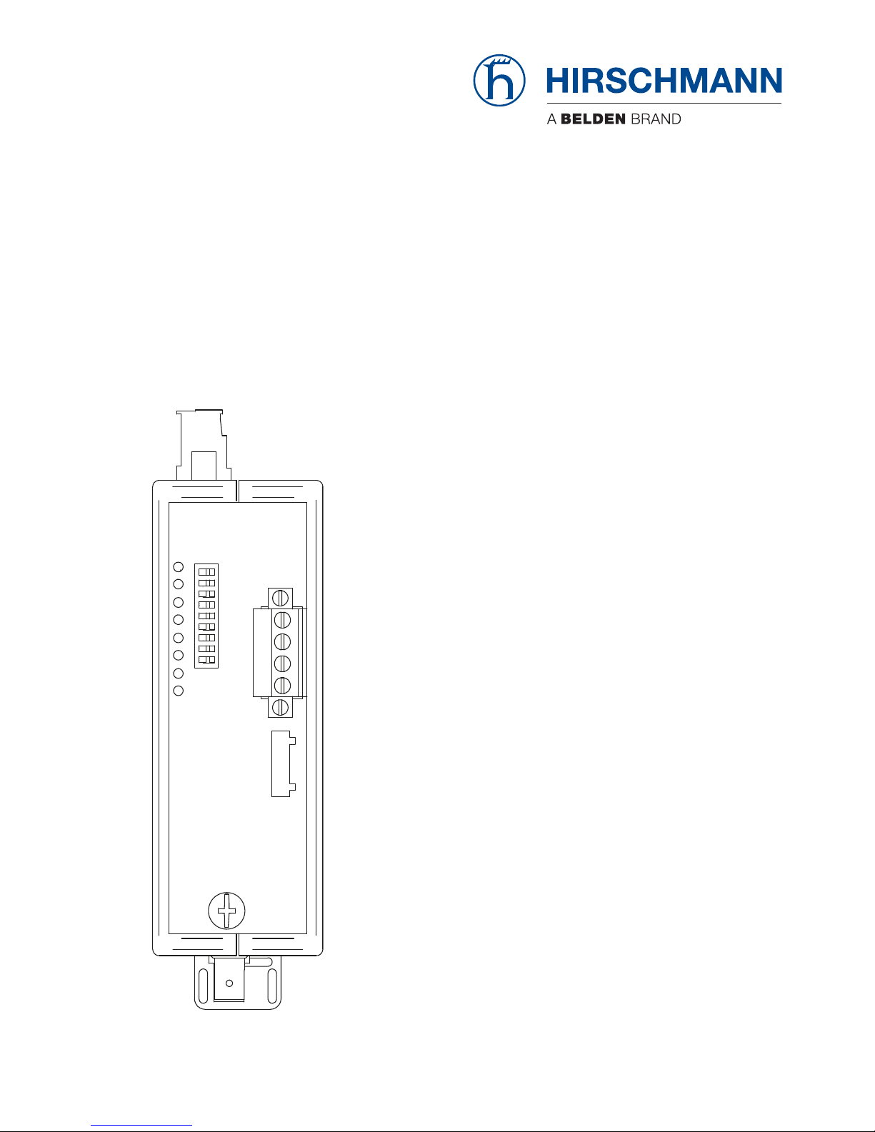
1.2 Device view
Front view using example of device variants OZD Genius... / OZD Genius G12-1300
1 8-pin terminal block for power supply, signal contact, measuring output
1a Pin assignment of the signal contact
1b Pin assignment of the power supply
1c Pin assignment of the measuring output
Ua1 for the optical port CH2
Ua2 for the optical port CH3
CH1
SystemCH1
CH3CH4
SHD OUT
SHD IN
SER2
SER1
1
4
5
3
2
1a
1c
1b
6
7
CH2
CH3
L1+
F1
0V
F2
L2+
Ua2
GND
Ua1
+24V
Fault
+24V
L1+
F1
0V
F2
L2+
Ua2
GND
Ua1
+24V
Fault
+24V
S0
S1
S2
S3
S4
S5
S6
S7
S8
1 0

Installation OZD Genius...
Release 01 09/2017
17
1.3 Display elements
2 8-pin DIP switch
Meaning of the DIP switches:
– S0 and S1 with function (Setting the data rate)
– S0 and S1 with function (Setting the optical transmit power)
– S2, S3, S4, S5, S8 without function
3 CH1 - electrical port
4 The information field for the electrical port 1 (CH1)
SHD OUT - Shield line, output (connected to casing)
SHD IN - Shield line, input (connected to casing via a capacitor)
SER2 = Data line S1
SER1 = Data line S2
5 CH2, CH3 - optical ports
6 Grounding screw
7 LED display element for system status and port status
Display Color Meaning
System None Supply voltage is too low
Green Data reception at all ports
Red No data reception for 500 ms at minimum one port
Ports None No data reception for 500 ms
Green Data reception; no error detected
orange/yellow Data reception, error detected:
– echo error (fiber in sending direction interrupted)
– malformed data packets (Jabber or Fragment)
CH3
System
CH1
CH2
CH1

18
Installation OZD Genius...
Release 01 09/2017
Signal contact Open – Supply voltage is too low
– No data reception for 500 ms at minimum one port
Closed Data reception at all ports
Display Color Meaning

Installation OZD Genius...
Release 01 09/2017
19
2 Network Topologies
2.1 Line topology without redundancy
Figure 1: Line topology without redundancy
This network topology is used in the case of an optical link between end
devices or bus segments.
It is advisable (but not essential) to terminate the first and last repeater in the
line with an ”optical short-circuit“. To do this, each input and output of the free
ports is connected via a short length of optical cable with BFOC connectors.
If the ”optical short-circuit“ is not provided, the vacant BFOC sockets must be
closed using the supplied protection caps. The associated port LEDs do not
light up, the system LEDs light up red, and the signaling contact closes
(fault).
Genius bus line
Fiber optic cable
Terminal unit(s)/
bus segment(s)
Terminal unit(s)/
bus segment(s)
Terminal unit(s)/
bus segment(s)
Terminal unit(s)/
bus segment(s)
CH3
TR
OZD Genius G12
CH2
TR
CH1
CH3
TR
CH2
TR
OZD Genius G12
CH1
CH3
TR
OZD Genius G12
CH2
TR
CH1
CH3
TR
OZD Genius G12
CH2
TR
CH1

20
Installation OZD Genius...
Release 01 09/2017
2.2 Redundant optical ring
Figure 2: Network structure in a redundant optical ring topology
This network topology is used in the case of an optical link between end
devices or bus segments. The implementation of a redundant link with OZD
Genius... repeaters ensures a high degree of reliability.
The failure of an optical cable between any two OZD Genius... repeaters
does not affect the availability of the network.
The repeaters detect the failure of an optical link. The port LED of the faulty
link is deactivated and the failure is indicated by illumination of the red system
LED and operation of the signal contact.
It is advisable to install the duplex optical cables of the two optical ports along
different routes.
Genius bus line
Fiber optic cable
Terminal unit(s)/
bus segment(s)
Terminal unit(s)/
bus segment(s)
Terminal unit(s)/
bus segment(s)
Terminal unit(s)/
bus segment(s)
CH3
TR
OZD Genius G12
CH2
TR
CH1
CH3
TR
CH2
TR
OZD Genius G12
CH1
CH3
TR
OZD Genius G12
CH2
TR
CH1
CH3
TR
OZD Genius G12
CH2
TR
CH1

Installation OZD Genius...
Release 01 09/2017
21
Figure 3: Alternative wiring system for network structure in redundant optical ring
topology
If problems are encountered with the configuration of a redundant optical ring
on account of excessively long fiber-optic line sections, connections can also
be implemented.
See figure 3 on page 21.
In this case, each repeater is linked (in spatial terms) with the next repeater
but one. Two adjacent repeaters must be interconnected at the start and end
of every such line. This prevents the individual fiber-optic line sections from
being” excessively long“.
It is advisable to install the duplex optical cables of the two optical channels
along different routes.
The maximum permissible network range for the ring topology depends on
both the number of OZD Genius G12... devices used and the data rate.
Genius bus line
Fiber optic cable
Terminal unit(s)/
bus segment(s)
CH3
TR
OZD Genius G12
CH2
TR
CH1
Terminal unit(s)/
bus segment(s)
CH3
TR
OZD Genius G12
CH2
TR
CH1
Terminal unit(s)/
bus segment(s)
CH3
TR
OZD Genius G12
CH2
TR
CH1
Terminal unit(s)/
bus segment(s)
CH3
TR
OZD Genius G12
CH2
TR
CH1
Terminal unit(s)/
bus segment(s)
CH3
TR
OZD Genius G12
CH2
TR
CH1

22
Installation OZD Genius...
Release 01 09/2017
3 Installation
The devices have been developed for practical application in a harsh
industrial environment.
Hirschmann supplies the device ready for operation.
To configure a subdomain, follow these steps:
Checking the package contents
Installing and grounding the device
Connecting the optic bus cables
Connecting the electric bus cables
Connecting the power supply
Connecting the signal contact
Setting the data rate
Setting the optical transmitting power
3.1 Checking the package contents
Proceed as follows:
Check whether the package includes all items named in the section
“Scope of delivery” on page 36.
Check the individual parts for transport damage.

Installation OZD Genius...
Release 01 09/2017
23
3.2 Installing and grounding the device
You have the following options for mounting your device:
Installing the device onto the DIN rail
Mounting the device on a mounting plate
Prerequisites:
Install the device in a location where the climatic threshold values
specified in the technical data are adhered to.
Ensure that there is sufficient room to connect the bus and power supply
cabling.
Connect the optical fiber line before mounting the repeater as this
simplifies the procedure.
If possible, the repeaters should only be installed on a mounting plate or
DIN rail with low-impedance and low-inductance grounding.
3.2.1 Installing the device onto the DIN rail
Note: The device is for mounting on a 35 mm DIN rail in accordance with DIN
EN 60715.
Proceed as follows:
Slide the upper snap-in guide of the device into the DIN rail.
Press the device downwards onto the clip-in bar.
2
1

24
Installation OZD Genius...
Release 01 09/2017
3.2.2 Mounting the device on a mounting plate
Note: The repeater has 3 through-holes. The through-holes allow to mount
the repeater to any flat surface, e.g. to the mounting plate of a switch cabinet.
Proceed as follows:
Make 3 holes in the mounting plate corresponding the drilling template.
Use the machine bolts (e.g. M3 x 40) to secure the repeater.
Ensure reliable electrical connection between the repeater casing and the
mounting plate.
Place toothed washers under the bolt heads to pierce the varnish.
3.2.3 Grounding the device
Functional grounding the device is by means of a separate connection on the
device.
Ground the device before connecting any other cables.
Disconnect the grounding only after disconnecting all other cables.
Ground the device via the ground screw.
Toothed washer
61,2 mm
40,6 mm
81,2 mm
Ø 3 mm
Ø 3 mm
mm in (inch)
81,2
61,2 2.45
3.2
40,6 1.6
3 0.12

Installation OZD Genius...
Release 01 09/2017
25
3.3 Connecting the optic bus cables
Proceed as follows:
Use a duplex fiber-optic cable with BFOC/2.5 (ST ®) connectors to
connect the individual repeaters.
Pay attention to the maximum cable length of the fiber-optic cable as well
as the possible types of fibers specified in the Technical Data.
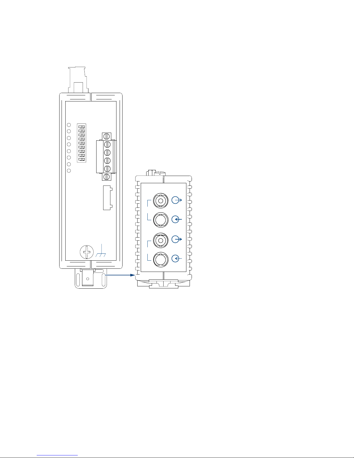
Make sure that each optical input is connected to an optical output at the
opposite end (“cross-overlink“). The corresponding BFOC sockets of the
two ports are marked on the lower front panel.
Ensure sufficient strain relief for the fiber-optic cables and pay attention to
their minimum bend radiuses.
Unused BFOC sockets are to be covered with the protective caps
supplied. Incident ambient light and, in particular, great ambient
brightness, can affect the network. The penetration of dust may impair
operation of the optical components.
optical output (Sending direction)
optical input (Receiving direction)
CH3

26
Installation OZD Genius...
Release 01 09/2017
3.4 Connecting the electric bus cables
WARNING
Genius bus lines which are completely or partially installed outdoors
should not be connected. Any lightning strikes in the immediate
vicinity could otherwise destroy the repeaters. Use F/O cables for
bus connections outside buildings.
Proceed as follows:
Only cables approved for the Genius bus should be used.
The Serial 1 port of a device is connected to the Serial 1 port of the
adjacent devices. This also applies for the Serial 2 port (no cross-over
connection).
The Shield In connection of a device is connected to the Shield Out
connection of the upstream device. As a result, the Shield In connection
of the first device as well as the Shield Out connection of the last device
remain free.
The beginning and end of the bus must be terminated with a resistor rated
according to the specifications for Genius bus cables. A resistor with a
rating of between 75 Ω and 150 Ω (0.5 W) must be used depending on the
cable used.
The signal processing time for the OZD Genius... repeater and the physical
delay caused by the fiber optic cable must be taken into consideration when
the system is configured. Detailed information regarding installation and
configuration can be found in the Genius bus specifications and the
configuration directives from the control unit manufacturer.
This interface is a 4-pin with a self-locking mechanism. The plug must be
engaged on the socket.
SHD OUT
SHD IN
SER2
SER1

Installation OZD Genius...
Release 01 09/2017
27
3.5 Connecting the power supply
Proceed as follows:
The OZD Genius... should only be supplied with a regulated safety extra-
low voltage of between 18 V and 32 V as defined in IEC 60950/EN 60950
/VDE 0805.
To improve the operating safety, a redundant power supply consisting of
separate sources can be used. The supply voltages can be supplied in
two ways:
via terminal 18 V ... 32 V of the terminal block
via terminal 18 V ... 32 V of the terminal block
The common negative connection in the middle of the terminal block is
indicated by (0 V).
The two voltages can have any values, even different ones, within the
specified limits.
L1+
F1
0V
F2
L2+
Ua2
GND
Ua1
+24V
Fault
+24V

28
Installation OZD Genius...
Release 01 09/2017
3.6 Connecting the signal contact
Note:
To connect the signal contact lines, remove the 8-pin screw terminal block
on top of the repeater from the device.
Use the correct pin assignment for the 8-pin terminal block.
Make sure that the electrical insulation of the connection cables of the
signal contacts is sufficient. Incorrect connections can destroy the
repeater.
On the 8-pin terminal block on the top of the repeater, the unconnected pins
of a relay can be used as signal contacts. When the OZD Genius... is working
correctly, the contact is closed. If there is an error or a power failure, the
contact is opened.
The following problems with the network and the repeater can be signaled by
means of the signal contact:
Supply voltage No supply voltage (with redundant supply voltage: loss of
all supply voltages)
Internal device errors
Received data Loss of received data at port 2 and/or port 3 (e.g.cable
breakage)
No data received at all ports
L1+
F1
0V
F2
L2+
Ua2
GND
Ua1
+24V
Fault
+24V

Installation OZD Genius...
Release 01 09/2017
29
3.7 Setting the data rate
Note: Use the dip switches S0 and S1 on the front panel of the OZD Genius...
to set the desired data rate.
The fiber-optic repeater OZD Genius G12... supports the data rates
153.6 kBaud (standard and extended),76.8 kBaud and 38.4 kBaud.
The switch settings for the data rates 153.6 kBaud Standard and
153.6 Extended are identical.
The positions of the switches S1 and S2 are only read in when the supply
voltage is applied. This ensures that no bus fault occurs if the two
switches are inadvertently set to the wrong positions.
If the device is already in operation, the supply voltage must be
disconnected before the data rate is changed. The new data rate is then
set using S1 and S2 and the supply voltage reconnected. When the
device is switched on, the new data rate is read in.
Data rate Switch position
153.6 dBm
Standard or Extended.
76.8 dBm
38.4 dBm
Not used
Table 4: Data rate and associated switch position
S0
S1
1 0
S0
S1
1 0
S0
S1
1 0
S0
S1
1 0

30
Installation OZD Genius...
Release 01 09/2017
3.8 Setting the optical transmitting power
Note:
S2, S3, S4, S5 and S8 do not have function on OZD Genius... .
The DIP switch S6 is used to set the transmit power of CH3.
The DIP switch S7 is used to set the transmit power of CH4.
3.9 Network range for line and ring topologies
It is possible to check whether a configuration is within the respective network
range limits by means of the following formula.
Checking the network range using the following formula
The following must apply:
[(I
O
× 5µs) + (IE×5µs) + (n
OZD×tRD
)] × 1.07 ≤ 0.5 × [tD + (dA - 1) × tS]
Verify that the dip switch S6 and S7 is set to position 1.
I
O
Length of optical fiber in ring (one ring loop) or in line [km]
I
E
Sum of the two longest electrical Genius bus segments which are connected to OZD
Genius... in ring or in line [km]
n
OZD
Number of OZD Genius... used
t
RD
Repeater delay - data transfer time through an OZD Genius...
(see table 5)
t
D
Delay time - minimum interval between two telegrams
(see table 5)
d
A
Minimum address distance between two Genius bus devices
t
S
Skip time - depends on data transmission rate
(see table 5)
Data rate [kBaud] 153.6 153.6 76.8 38.4
Mode Standard. Extended. Extended. Extended.
t
RD
0.8 0.8 1.2 2.3
t
D
70 140 140 280
t 26 52 104 208
Table 5: Timing
CH 3
CH 4
CH 1
10
S
1
S
0
S
6
S
5
S
3
S
2
S
4
S
7
S 8
n.c.
n.c.
n.c.
n.c.
n.c.

Installation OZD Genius...
Release 01 09/2017
31
Figure 4: Example of network configuration with 5 OZD Genius... devices (two
longest Genius bus segments are identified)
Serial 1
Serial 2
Shield in
Shield out
Terminating
resistor
Serial 1
Serial 2
Shield in
Shield out
Terminating
resistor
Serial 1
Serial 2
Shield in
Shield out
Terminating
resistor
Serial 1
Serial 2
Shield in
Shield out
Terminating
resistor
Serial 1
Serial 2
Shield in
Shield out
Terminating
resistor
Serial 1
Serial 2
Shield in
Shield out
Terminating
resistor
Serial 1
Serial 2
Shield in
Shield out
Terminating
resistor
Serial 1
Serial 2
Shield in
Shield out
Terminating
resistor
Duplex fiber optic cable
Electrical bus line
Two longest electrical Genius bus segments
l
O
5 x OZD Genius G12
l
E1
l
E2
lE = lE1 + l
E2
n
OZD
= 5

32
Installation OZD Genius...
Release 01 09/2017
4 Disassembly
To remove the device, pull down on the locking slide.
1

Installation OZD Genius...
Release 01 09/2017
33
5 Technical data
General technical data
Device variant OZD Genius... OZD Genius G12-1300
Dimensions
W × H × D
See “Dimension drawings” on page 35.
Weight approx. 19.75 oz (560 g)
Supply voltage
See “Requirements for connecting electrical wires” on page 6.
Nominal voltage DC 24 V
Voltage range DC incl. maximum
tolerances
18 V ... 32 V
Connection type 4-pin terminal block
Power loss buffer > 10 ms at 20.4 V DC
Overload current protection at input Non-replaceable fuse
Back-up fuse for each voltage input
Nominal rating:
Characteristic:
2A
slow blow
Peak inrush current < 4 A
Signal transmission
Data rate 153.6 kBit/s, 76.8 kBit/s, 38.4 kBit/s
Cascadability not limited
Signal processing time
(any input/output)
0.9 µ at 153.6 kBit/s
1.6 µ at 76.8 kBit/s
3.1 µ at 38.4 kBit/s
Electrical port
Input/output signal Genius bus
OZD Genius... cable
– Length
– Attenuation at 1 MHz
< 250 m
< 8 dB for 150 Ω cable
< 5 dB for 100 Ω cable
Connection options max. 32 end devices
Electrical isolation
– Shielding in/Shielding out
– Data cable/casing
Yes
Yes
terminating resistor Must be attached outside to connector
Signal contact
See “Requirements for connecting electrical wires” on page 6.
Switching current max. 1 A
Switching voltage under UL conditions: max. 30 V DC, resistive load
Climatic conditions during operation
Ambient temperature +32 °F ... +140 °F (0 °C ... +60 °C)
Humidity 5 % ... 95 %
(non-condensing)
Air pressure minimum 700 hPa (+9842 ft; +3000 m)

34
Installation OZD Genius...
Release 01 09/2017
Climatic conditions during storage
Ambient temperature −40 °F ... +176 °F (−40 °C ... +80 °C)
Humidity 5 % ... 95 %
(non-condensing)
Air pressure minimum 700 hPa (+9842 ft; +3000 m)
Pollution degree 2
Protection classes
Laser protection Class 1 in compliance with IEC 60825-1
Degree of protection IP40
Optical port P G G-1300
Wavelength 650 nm 860 nm 1300 nm
Launchable optical power – – –
in fiber 10/125 (default) – – −19 dBm
into fiber 50/125 (default) −17 dBm −17 dBm
into fiber 62.5/125 (default) – −13 dBm −17 dBm
Receiver sensitivity −25 dBm −28 dBm −29 dBm
Receiver overload limit 0 dBm −1dBm −3dBm
Damping values of the fiber
optic
P G G-1300
Wavelength 650 nm 860 nm 1300 nm
Damping values:
Fiber 10/125 – – 0.5 dB/km
Fiber 50/125 – 3 dB/km 1 dB/km
Fiber 62.5/125 – 3.5 dB/km 1 dB/km
Fiber 200/230 10 dB/km 8 dB/km –
Fiber 980/1000 0.225 dB/m – –
Transmission distance
a
a. The specified distance allowed between two OZD Genius G12-1300 must not be exceeded
regardless of the optical power budget.
G G-1300
Wavelength 860 nm 1300 nm
System reserve 3 dB 2 dB
Transmission distance:
Fiber 10/125 – 10000 m
Fiber 50/125 (default) 2700 m 10000 m
Fiber 62.5/125 (default) 3100 m 10000 m

Installation OZD Genius...
Release 01 09/2017
35
Dimension drawings
Power consumption/power output
Device name Maximum power consumption Maximum power output
OZD Genius... 4.8 W 16.3 Btu (IT)/h
12,47
0.49
110,4
4.35
10,75
0.42
16,35
0.64
16,75
0.66
96,7
3.8
39,5
1.56
mm
inch

36
Installation OZD Genius...
Release 01 09/2017
6 Scope of delivery, order numbers and
accessories
Scope of delivery
Order numbers/product description
Number Article
1× Device
1 × General safety instructions
Device name Order number
OZD Genius G12 942 148-012
OZD Genius G12-1300 942 148-013

Installation OZD Genius...
Release 01 09/2017
37
7 Underlying technical standards
The device has an approval based on a specific standard only if the approval
indicator appears on the device casing.
The device generally fulfills the technical standards named in their current
versions.
Name
C-Tick Declaration Australian Radiocommunication Act 1998
Australian Radiocommunication Standard 2008
CSA C22.2 No. 142 Canadian National Standard(s) – Process Control Equipment –
Industrial Products
FCC 47 CFR Part 15 Code of Federal Regulations
DNVGL-CG-0339 Environmental test specification for electrical, electronic and
programmable equipment and systems.
UL/IEC 61010-1,
UL/IEC 61010-2-201
Safety for Control Equipment
EN 55032 Electromagnetic compatibility of multimedia equipment –
Emission Requirements
EN 61000-3-2 Electromagnetic compatibility (EMC) - Part 3-2: Limits - Limits for
harmonic current emissions
EN 61000-3-3 Electromagnetic compatibility (EMC) - Part 3-3: Limits - Limitation
of voltage changes, voltage fluctuations and flicker.
EN 61000-6-2 Electromagnetic compatibility (EMC) – Part 6-2: Generic
standards – Immunity for industrial environments
EN 61000-6-4 Electromagnetic compatibility (EMC) – Part 6-4: Generic
standards – Emission standard for industrial environments
EN 61131-2 Programmable controllers – Part 2: Equipment requirements and
tests
Table 6: List of the technical standards

38
Installation OZD Genius...
Release 01 09/2017
8 Troubleshooting
This chapter helps you to localize faults after they have been indicated (by
LEDs or signal contacts).
Fault indicated on the system LED
Check that the supply voltage is being supplied.
Check that the supply voltage is connected correctly.
Fault displayed at CH1
Check that the correct data rate has been set.
Check that the serial data line has been connected correctly.
Check that the terminating resistor has been connected correctly.
Fault displayed at CH2, CH3
Check that the optical fiber from the transmitting OZD Genius... is not
broken.
Check that the optical fibers are not too long.
Check that the optical fibers are not crossed.
Check that the ports are not connected incorrectly.

Installation OZD Genius...
Release 01 09/2017
39
A Further support
Technical questions
For technical questions, please contact any Hirschmann dealer in your area
or Hirschmann directly.
You find the addresses of our partners on the Internet at
http://www.hirschmann.com.
A list of local telephone numbers and email addresses for technical support
directly from Hirschmann is available at
https://hirschmann-support.belden.eu.com.
This site also includes a free of charge knowledge base and a software
download section.
Hirschmann Competence Center
The Hirschmann Competence Center is ahead of its competitors on three
counts with its complete range of innovative services:
Consulting incorporates comprehensive technical advice, from system
evaluation through network planning to project planning.
Training offers you an introduction to the basics, product briefing and user
training with certification.
You find the training courses on technology and products currently
available at http://www.hicomcenter.com.
Support ranges from the first installation through the standby service to
maintenance concepts.
With the Hirschmann Competence Center, you decided against making any
compromises. Our client-customized package leaves you free to choose the
service components you want to use.
Internet:
http://www.hicomcenter.com

40
Installation OZD Genius...
Release 01 09/2017

Installation OZD Genius...
Release 01 09/2017
41

 Loading...