

Hirschmann OZD 485 G12 PRO User Manual
Manual
Universal RS 485 Fiberoptic Repeater
OZD 485 G12(-1300) PRO
Hirschmann. Simply a good Connection.
OZD 485 G12 PRO
System
P1
DA/STAT
01
S1
S 2
S 3
S 4
RT+
K1+
K1+
K1-
K1-
RT-
RT-
K2-
K2-
K2+
K2+
RT+
Ua2
GND
Ua3
RM
31P22
Port 1

The performance features described here are binding
only if they have been expressly agreed when the contract was made. We have checked the content of this
document for consistency with the hardware and software it describes. However, inconsistencies cannot be
ruled out, and thus we cannot guarantee absolute
consistency. Nevertheless, the information in the document is checked regularly. Necessary corrections
are contained in the following printings. We are grateful for any suggested improvements.
Technical modifications reserved.
This document may not be passed on, copied, nor
may its contents be used or distributed, unless expressly permitted. Violators will be held liable for compensation. All rights are reserved, particularly if a
patent is granted or the design is registered.
© Hirschmann Automation and Control GmbH
All Rights Reserved
Note
We wish to point out that the content of this manual is
not part of a previous or existing agreement, consent ,
or legal relationship, or shall not amend same. All the liabilities of Hirschmann result from the respective sales
contract, which also contains the complete and solely
valid guarantee regulations. These contractual guarantee
specifications are neither enhanced nor restricted by the
information in this manual .
We also wish to point out that for reasons of comprehensibility, not every conceivable problem relating to the
use of this device can be described in this manual.
Should you require further information , or should particular problems occur which are not dealt with in sufficient detail
in this manual, you can request the required information
from your local Hirsch mann dealer or directly from
Hirschmann (for address, see section “Note on CE
Marking”).
Order Numbers
OZD 485 G12 PRO 943 894-321
OZD 485 G12-1300 PRO 943 895-321
Manual 039 555-001
Universal RS 485 Fiberoptic
Repeater OZD 485 G12(-1300) PRO

1
OZD 485 G12(-1300) PRO Version 04 12/2014
Notes on safety
This manual contains instructions to be observed for
ensuring your personal safety and for preventing damage.
The warnings appear next to a warning triangle with a
different heading depending on the degree of danger
posed:
z
Danger!
Means that death, serious physical inj ury or considerable damage to equipment will occur if the
required precautionary measures are not taken.
z
Warning!
Means that death, serious physical injury or considerable damage to equipment can occur if the
required precautionary measures are not taken.
z
Caution!
Means that minor physical inj ury or damage to
equipment can occur if the required precautionary
measures are not taken.
Note:
Contains important information on the product, on how to
manage the product, or on the respective section of the
documentation to which your particular attention is being
drawn.
Qualification requirements for personnel
Note:
Qualified personnel as understood in this manual and the
warning signs, are persons who are familiar with the
setup, assembly, startup, and operation of this product
and are appropriately qualified for their job. This includes, for example, those persons who have been:
– trained or instructed or authorized to switch on and off,
to ground and to label power circuits and devices or
systems in accordance with current safety engineering
standards;
– trained or instructed in the care and use of appropriate
safety equipment in accordance with the current standards of safety engineering;
– trained in providing first aid.
General safety instructions
D
This device is operated by electricity. You must follow
precisely the prescribed safety requirements in the
operating manual that relate to the voltage connect ions!
D
Make sure that the electrical installation meets local
or national safety regulations.
z
Warning!
Non-observance of these safety instructions can
cause materia l damage and/or serious injuries.
Only appropriately qualified per sonnel should work
on this device or in its vicinity. This per sonnel must
be thoroughly familiar with all the warnings and
maintenance procedures in accordance with this
operating manual.
The proper and safe operation of this device
depends on proper handling during transport,
proper storage and assembly, and conscientious
operation and maintenance procedures. Never
start operation with damaged components.
z
Warning!
Any work that may be required on the electrical
installation may only be carried out by personnel
trained for this purpose.
z
Warning!
LASER CLASS 1 in compliance with
IEC 60825-1 (2014).
Correct operation
Please note the following:
z
Warning!
The device may only be used for those purposes
specified in the catalog and in the technical description, and only in combination with external
devices and components approved by Hirschmann. The proper and safe operation of this product depends on proper handling during transport,
proper storage and assembly, and conscientious
operation and maintenance procedures.

2
OZD 485 G12(-1300) PRO Version 04 12/2014
Safety instructions for supply voltage
D
Only switch on the device when the housing is
closed.
z
Warning!
The devices may only be connected to the supply
voltage shown on the type plate.
The devices are designed for operation with safety
extra-low voltage. Accordingly, only PELV circuits
or SELV circuits with voltage restrictions in line
with IEC/EN 60950 may be connected to the supp ly
voltage connections and the signal contact.
D
If you are operating the module with an external volt age: Only supply the system with a low safety voltage
in compliance with IEC/EN 60950.
Relevant for North America:
D
The device may only be connected to a supply
volt age of class 2 that fulfils the requirements of the
National Electrical Code, Table 11(b). If the voltage
is being supplied redundantly (two different voltage
sources), the combined supply voltages must fulfil
the requirements of the National Electrical Code,
Table 11(b).
D
Use 90 or 90°C copper(CU) wire only.
Safety instructions for environment
z
Warning!
The device may only be operated in the specified
ambient temperature and relative air humidity
(non-condensing).
D
Select the installation site so that the climatic threshold values specified in the technical data are
adhered to.
D
Only to be used in an environment with contamination
level 2 (IEC 60664-1).
Safety instructions for housing
z
Warning!
Only technicians authorized by Hirschmann are
permitted to open the housing.
Underlying norms and standards
The devices fulfill the following norms and standards:
– EN 61000-6-2:2001 Generic standards –
Immunity for industrial environments
– EN 55022:1998 + A1 2000+A2:2003 – Information tech-
nology equipment – Radio disturbance characteristics
– EN 61131-2: Programmable controllers
– EN 60825-1 Safety of laser products
– FCC 47 CFR Part 15:2004 – Code of Federal
Regulations
Note on the CE marking
7
The devices comply with the regulations of the
following European directives:
89/336/EEC
Council Directive on the harmonization of the legal regulations of member states on electromagnetic compatibility
(amended by Directives 91/263/EEC, 92/31/EEC and
93/68/EEC).
The precondition for compliance with EMC limit values is
strict adherence to the installation guidelines specified in
this description and operating instructions.
The EU declaration of conformity is kept available for the
responsible authorities in accordance with the abovementioned EU directives at:
Hirschmann Automation and Control GmbH
Stuttgarter Strasse 45 - 51
72654 Neckartenzlingen
Germany
Telephone +49 (0) 1805 14-1538
Email HAC.Support@Belden.com
The product can be used in the residential sphere (residential sphere, business and trade sphere and small
companies) and in the industrial sphere.
– Interference immunity:
EN 61000-6-2:2001
– Interference emissions:
EN 55022:1998+A1:2000+A2:2003 Class A
z
Warning!
This is a Class A device. This equipment may
cause radio interference if used in a residential
area; in this case it is the operator’s responsibility
to take appropriate measures.

3
OZD 485 G12(-1300) PRO Version 04 12/2014
FCC RULES
This device complies with part 15 of the FCC Rules.
Operation is subject to the following two conditions:
(1) This device may not cause harmful interference, and
(2) This device must accept any interference received,
including interference that may cause undesired operation.
Note: This equipment has been tested and found to
comply with the limits for a Class A digital device, pursuant to part 15 of the FCC Rules. These limits are designed to provide reas onable protection against harmful
interference when the equipment is operated in a commercial environment. This equipment generates, uses,
and can radiate radio frequency energy and, if not installed and used in accordance with the instruction man ual,
may cause harmful interference to radio communications. Operation of this equipment in a residential area is
likely to cause harmful interference in which case the
user will be requir ed to correct the interference at his
own expense.
C-Tick
Australia / New Zealand
This product meets the requirements of the
AS/NZS 3548 standard.
N1337
Certifications
cUL508
Please note the important information in: Chapter 5.4,
”Use in North America“, page 23.
ISA12.12.01
Hazardous Locations Class1 Div 2 Groups
A, B, C und D
Please note the important information in: Chapter 5.4
”Use in North America“, page 23.
ATEX Directive 94/9/EC Zone 2 3G
Please note the important information in: Chapter 5.2
”Use in Ex-zone 2 according to ATEX 94/9/EC“, page 21.
Note:
Only the certifications indicated on the label attached to
each device are applicable.
Recycling note
,
After usage, this product must be disposed of
properly as electronic waste in accordance with
the current disposal regulations of your county/
state/country.

4
OZD 485 G12(-1300) PRO Version 04 12/2014

5
Contents
OZD 485 G12(-1300) PRO Version 04 12/2014
1 Introduction . . . . . . . . . . . . . . . . . . . . . . . . . . . . . . . . . . . . . . . . . . . . . . . . . . . . . . . . . . . . . . 7
2 Half/full duplex operation . . . . . . . . . . . . . . . . . . . . . . . . . . . . . . . . . . . . . . . . . . . . . . . . . . 9
2.1 Half duplex operation . . . . . . . . . . . . . . . . . . . . . . . . . . . . . . . . . . . . . . . . . . . . . . . . . . . . . . . . . . . 9
2.2 Full duplex operation . . . . . . . . . . . . . . . . . . . . . . . . . . . . . . . . . . . . . . . . . . . . . . . . . . . . . . . . . . . 10
3 Tristate recognition . . . . . . . . . . . . . . . . . . . . . . . . . . . . . . . . . . . . . . . . . . . . . . . . . . . . . . . . 11
3.1 Tristate recognition through permanent high . . . . . . . . . . . . . . . . . . . . . . . . . . . . . . . . . . . . . . . . 11
3.2 Tristate recognition through differential voltage . . . . . . . . . . . . . . . . . . . . . . . . . . . . . . . . . . . . . . . 12
4 Network topologies . . . . . . . . . . . . . . . . . . . . . . . . . . . . . . . . . . . . . . . . . . . . . . . . . . . . . . . . 13
4.1 Line topology without redundancy . . . . . . . . . . . . . . . . . . . . . . . . . . . . . . . . . . . . . . . . . . . . . . . . . 13
4.2 Redundant ring . . . . . . . . . . . . . . . . . . . . . . . . . . . . . . . . . . . . . . . . . . . . . . . . . . . . . . . . . . . . . . . . 14
4.3 Star distributor . . . . . . . . . . . . . . . . . . . . . . . . . . . . . . . . . . . . . . . . . . . . . . . . . . . . . . . . . . . . . . . . 15
4.4 Network range . . . . . . . . . . . . . . . . . . . . . . . . . . . . . . . . . . . . . . . . . . . . . . . . . . . . . . . . . . . . . . . . 16
4.5 Cascadability and data rate . . . . . . . . . . . . . . . . . . . . . . . . . . . . . . . . . . . . . . . . . . . . . . . . . . . . . . 16
5 Installation . . . . . . . . . . . . . . . . . . . . . . . . . . . . . . . . . . . . . . . . . . . . . . . . . . . . . . . . . . . . . . . 19
5.1 Installation guidelines . . . . . . . . . . . . . . . . . . . . . . . . . . . . . . . . . . . . . . . . . . . . . . . . . . . . . . . . . . . 19
5.2 Use in Ex-zone 2 according to ATEX RL 94/9EG . . . . . . . . . . . . . . . . . . . . . . . . . . . . . . . . . . . . . . 21
5.3 Control Drawing . . . . . . . . . . . . . . . . . . . . . . . . . . . . . . . . . . . . . . . . . . . . . . . . . . . . . . . . . . . . . . . 23
5.4 Use in North America . . . . . . . . . . . . . . . . . . . . . . . . . . . . . . . . . . . . . . . . . . . . . . . . . . . . . . . . . . . 25
5.5 Installing procedure . . . . . . . . . . . . . . . . . . . . . . . . . . . . . . . . . . . . . . . . . . . . . . . . . . . . . . . . . . . . 25
5.6 Installing repeater . . . . . . . . . . . . . . . . . . . . . . . . . . . . . . . . . . . . . . . . . . . . . . . . . . . . . . . . . . . . . . 26
5.7 Installing terminating resistor and pull-up/pull-down resistor s . . . . . . . . . . . . . . . . . . . . . . . . . . . 27
5.8 Setting DIL switches . . . . . . . . . . . . . . . . . . . . . . . . . . . . . . . . . . . . . . . . . . . . . . . . . . . . . . . . . . . . 28
5.9 Connecting the optic bus cables . . . . . . . . . . . . . . . . . . . . . . . . . . . . . . . . . . . . . . . . . . . . . . . . . . 29
5.10 Connecting the electric bus cables . . . . . . . . . . . . . . . . . . . . . . . . . . . . . . . . . . . . . . . . . . . . . . . . 29
5.11 Connecting the function ground . . . . . . . . . . . . . . . . . . . . . . . . . . . . . . . . . . . . . . . . . . . . . . . . . . 30
5.12 Connecting the signal contact lines (optional) . . . . . . . . . . . . . . . . . . . . . . . . . . . . . . . . . . . . . . . . 30
5.13 Connecting the analog voltage outputs (optional) . . . . . . . . . . . . . . . . . . . . . . . . . . . . . . . . . . . . . 31
5.14 Connecting the operating voltage supply . . . . . . . . . . . . . . . . . . . . . . . . . . . . . . . . . . . . . . . . . . . 32
5.15 Checking the LED indicators . . . . . . . . . . . . . . . . . . . . . . . . . . . . . . . . . . . . . . . . . . . . . . . . . . . . . 32
Contents

Contents
6
OZD 485 G12(-1300) PRO Version 04 12/2014
6 Bus configurations . . . . . . . . . . . . . . . . . . . . . . . . . . . . . . . . . . . . . . . . . . . . . . . . . . . . . . . . 33
6.1 BITBUS . . . . . . . . . . . . . . . . . . . . . . . . . . . . . . . . . . . . . . . . . . . . . . . . . . . . . . . . . . . . . . . . . . . . . . 33
6.2 DIN measurement bus . . . . . . . . . . . . . . . . . . . . . . . . . . . . . . . . . . . . . . . . . . . . . . . . . . . . . . . . . . 34
6.3 InterBus-S . . . . . . . . . . . . . . . . . . . . . . . . . . . . . . . . . . . . . . . . . . . . . . . . . . . . . . . . . . . . . . . . . . . 35
6.4 Modbus RTU/Modbus ASCII . . . . . . . . . . . . . . . . . . . . . . . . . . . . . . . . . . . . . . . . . . . . . . . . . . . . . 35
6.4.1 Specification of the Modbus variants . . . . . . . . . . . . . . . . . . . . . . . . . . . . . . . . . . . . . . . . . . 36
6.4.2 Without Line Polarization . . . . . . . . . . . . . . . . . . . . . . . . . . . . . . . . . . . . . . . . . . . . . . . . . . . . 37
6.4.3 With Line Polarization . . . . . . . . . . . . . . . . . . . . . . . . . . . . . . . . . . . . . . . . . . . . . . . . . . . . . . 38
6.5 Configuration of other bus systems . . . . . . . . . . . . . . . . . . . . . . . . . . . . . . . . . . . . . . . . . . . . . . . . 39
7 Help with problems . . . . . . . . . . . . . . . . . . . . . . . . . . . . . . . . . . . . . . . . . . . . . . . . . . . . . . . . 41
7.1 LED displays . . . . . . . . . . . . . . . . . . . . . . . . . . . . . . . . . . . . . . . . . . . . . . . . . . . . . . . . . . . . . . . . . . 41
7.2 Troubleshooting . . . . . . . . . . . . . . . . . . . . . . . . . . . . . . . . . . . . . . . . . . . . . . . . . . . . . . . . . . . . . . . 42
7.3 Problem reporting . . . . . . . . . . . . . . . . . . . . . . . . . . . . . . . . . . . . . . . . . . . . . . . . . . . . . . . . . . . . . 43
7.4 Contact address . . . . . . . . . . . . . . . . . . . . . . . . . . . . . . . . . . . . . . . . . . . . . . . . . . . . . . . . . . . . . . . 44
8 Technical data . . . . . . . . . . . . . . . . . . . . . . . . . . . . . . . . . . . . . . . . . . . . . . . . . . . . . . . . . . . . 45
7
1 Introduction
OZD 485 G12(-1300) PRO Version 04 12/2014
1 Introduction
The RS 485 Fiberoptic Repeater OZD 485 G12(-1300)
PRO is intended for use in optical RS 485 fieldbus networks such as Modbus RTU, Modbus ASCII, BITBUS
and company-specific busses .
It enables you to convert electrical RS 485 signals to
optical ones, and the reverse.
With the OZD 485 G12(-1300) PRO Repeaters, you can
construct univer sal half (2-wire) or full (4-wire) duplex
transmission systems with RS 485 interfaces.
You can integrate the Repeaters into existing electrical
RS 485 fieldbus networks. You can also build up a
complete optical RS 485 fieldbus network in line, ring or
star topoligies with OZD 485 G12(-1300) PRO Repeaters.
The housing consists of two plastic sections and a front
panel made of metal. It can be mounted on a DIN rail.
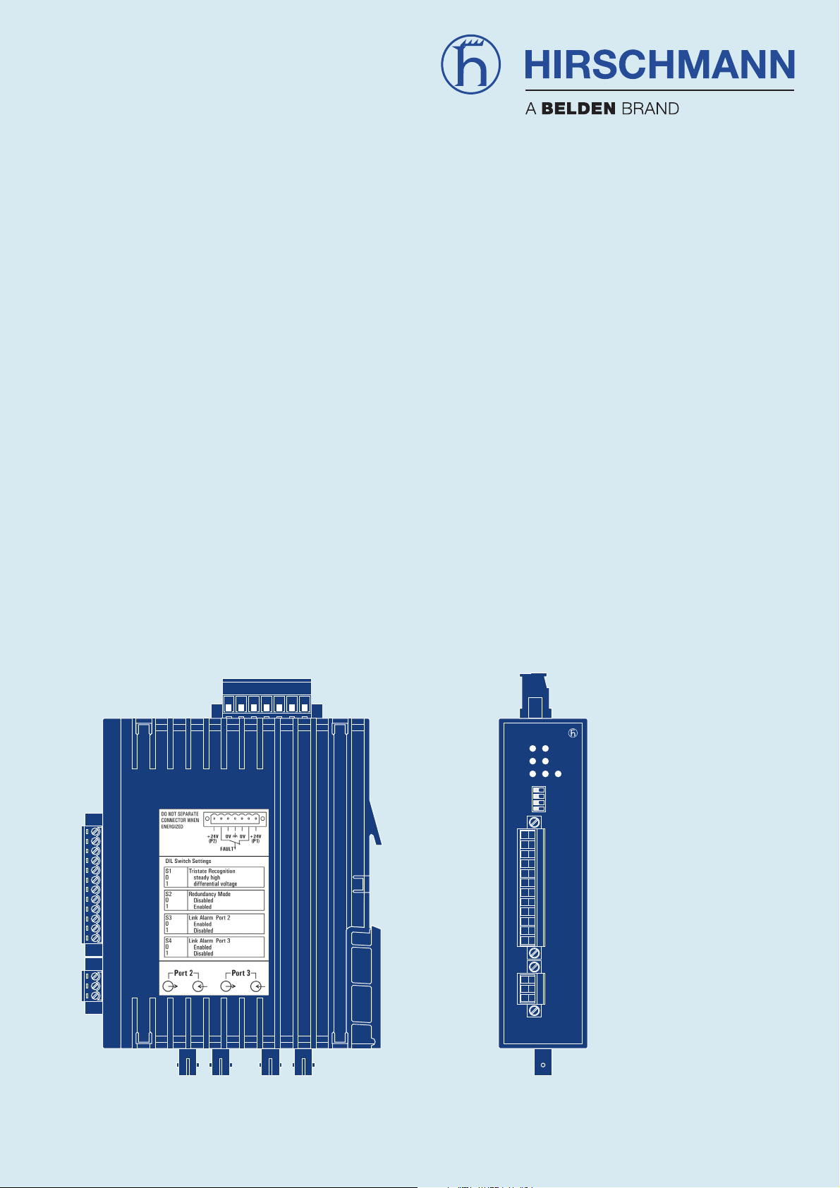
Ports
The Repeater has three independent ports, which in turn
consist of a transmitter and a receiver component.
Port 1 is a 12-pin screw terminal block, and ports 2 and 3
are optical BFOC/2.5 (ST
®
) sockets.
Power supply
The power supply is +18 V to +24 V (for non-hazardous
locations only: +18 V to +32 V) direct current.
To improve the operating safety, a redundant operating
power supply consisting of two separate sources can
be used. For this purpose, you must connect the two
operating voltages to two different terminals of the 7-pin
screw-type terminal block .
12-pin screw
terminal block for
port 1, electrical
and
pull-up/pull-down
resistors and
bus terminating
resistor
7-pin
terminal block
for operating
power supply
and
signal contact
LED
indicators
Switch for
tristate recognition,
redundancy mode
and link status
monitoring
Port 3
optical,
BFOC/2.5
socket
Port 2
optical,
BFOC/2.5
socket
01
S 2
S1
S 4
S 3
System
OZD 485 G12 PRO
DA/STAT
31P22
RM
P1
RT+
K1+
K1+
K1-
K1-
RT-
RT-
K2-
K2-
K2+
K2+
RT+
Ua2
GND
Ua3
Port 1
3-pin
screw
terminal block
for analog
voltage outputs
Fig. 1: Fiberoptic Repeater OZD 485 G12(-1300) PRO with location of individual ports, terminal blocks and LED displays

1 Introduction
8
OZD 485 G12(-1300) PRO Version 04 12/2014
Both connections are uncoupled by means of diodes to
prevent reverse voltage supply or destruction through
incorrect pole connection.
There is no load distribution between the sources. With
redundant supply, the power supply unit with the higher
output voltage must supply the repeater alone.
Signal contact
A signal contact (relay with unconnected contacts) is
used to signal various disruptions in the repeaters . The
signal contact is also connected to the 7-pin screw-type
terminal block.
LEDs
Seven one- and two-colored light-emitting diodes signal
the current operating status and any possible operating
errors.
Configuration
You can easily set the configuration to meet your specific
requirements by means of DIL code switches, which can
easily be operated from outside.
The following settings are possible:
U Tristate recognition
U Redundancy mode
U Signaling a lower power input at optical port 2
U Signaling a lower power input at optical port 3
Glass fiber technology
The use of glass fiber transmission technology enables a
very large transmission range and ensures optimal protection from EMC effects on the transmission path and
– due to the potential separation – on the Repeater itself.
Transmission speed
The RS 485 Fiberoptic Repeater OZD 485 G12(-1300)
PRO supports all data rates from 0 to 1.5 MBit/s NRZ.
Network range
The permissible network range for the line, ring or star
topology depends on the bus system and terminal devices used. See chapter 4.4, page 16.
Redundancy
The redundant ring enables a very high level of
transmiss ion reliability.
The redundant operating power supply can further
improve the operating reliability.
Device models
The RS 485 Fiberoptic Repeaters OZD 485 G12 … PRO
are available as OZD 485 G12 PRO for multi-mode fibers
(50/125 µm and 62.5/125 µm) and as OZD 485 G12-1300
PRO for single- mode fibers (10/125 µm) and multi-mode
fibers (50/125 µm and 62.5/125 µm).
Compatibilty with other RS 485 Fiberoptic
Repeaters
The OZD 485 G12 PRO may be operated via the optical
ports
– together with the RS 485 Fiberoptic Repeater OZD 485
G12, or
– together with the RS 485 Fiberoptic Repeater OZD 485
G12 BAS, if only those properties that are also suppor-
ted by the OZD 485 G12 BAS are used in the entire
network.
The OZD 485 G12-1300 PRO may be operated via
the optical ports
– together with the RS 485 Fiberoptic Repeater OZD 485
G12-1300.
2.1 Half-duplex operation
9
2 Half/full duplex operation
OZD 485 G12(-1300) PRO Version 04 12/2014
2 Half/full duplex operation
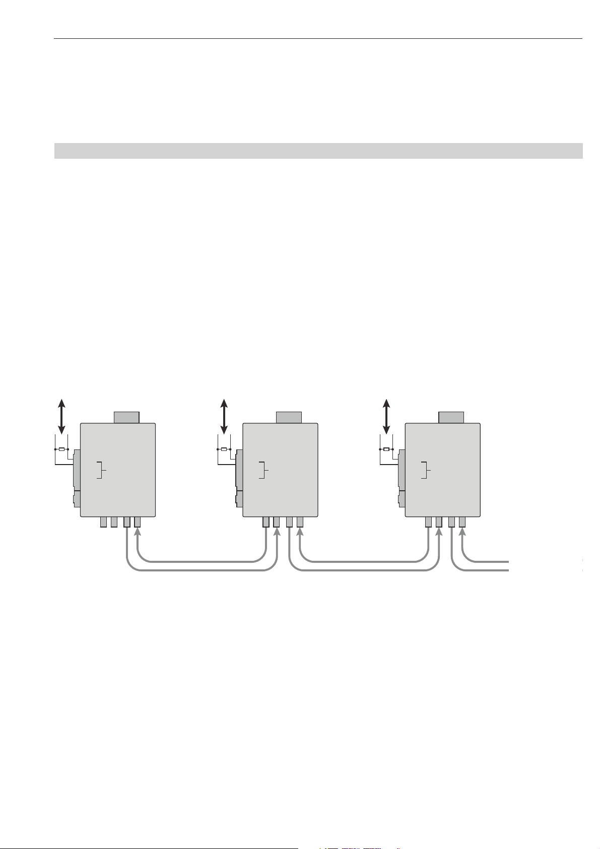
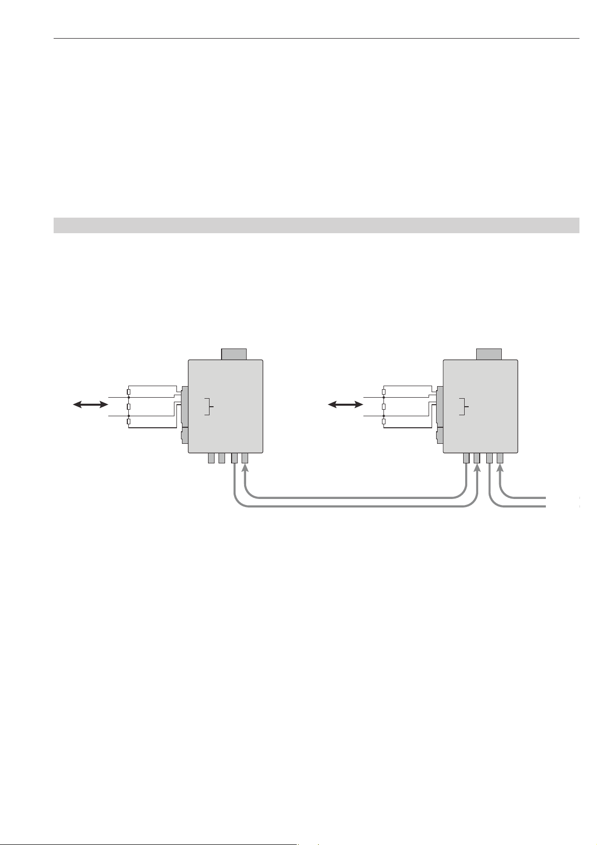
2.1 Half-duplex operation
Fig. 2: Half-duplex mode – data channel K1 is used for data transmission, and data channel K2 is not used
Data
K 1
Port 1
K 1
K 2
Port 3Port 2
Data
K 1
Port 1
K 1
K 2
Port 3Port 2
Data
K 1
Port 1
K 1
K 2
Port 3Port 2
The two data channels of the electrical port, K1 and K2,
can transmit data simultaneously and independently of
one another in half-duplex mode
1)
. Each data channel
replaces a 2-wire cable.
In half-duplex mode, the arbitration procedure used by
the connected devices must ensure that at any given
time, only one device can access the bus, like in
master/slave operation. Access procedures where there
is a risk of collisions, such as CAN, are not permissible.
In half-duplex mode, consecutive data telegrams must
be separated by a minimal time gap so that the end of a
data telegram can be definitively recognized and thus
the data direction can be switched in the OZD 485 G12
(-1300) PRO. For the tristate recognition through permanent high, this gap is 3.5 µs, while for the tristate reco gnition through differential voltage, it is 1 µs.
You can cascade a number of OZD 485 G12(-1300) PRO
via the optical interfaces
1)
. Devices or bus segments
may be connected to the electrical interfaces of all the
cascaded OZD 485.
1) When you use both data channels K1 and K2 at the same time and
while cascading the repeaters the increased jitter causes a reduction
in the maximum permissible transmission rate and/or the cascadability. See chapter 4.5, page 16.
2 Half/full duplex operation 2.1 Half-duplex operation
10
OZD 485 G12(-1300) PRO Version 04 12/2014
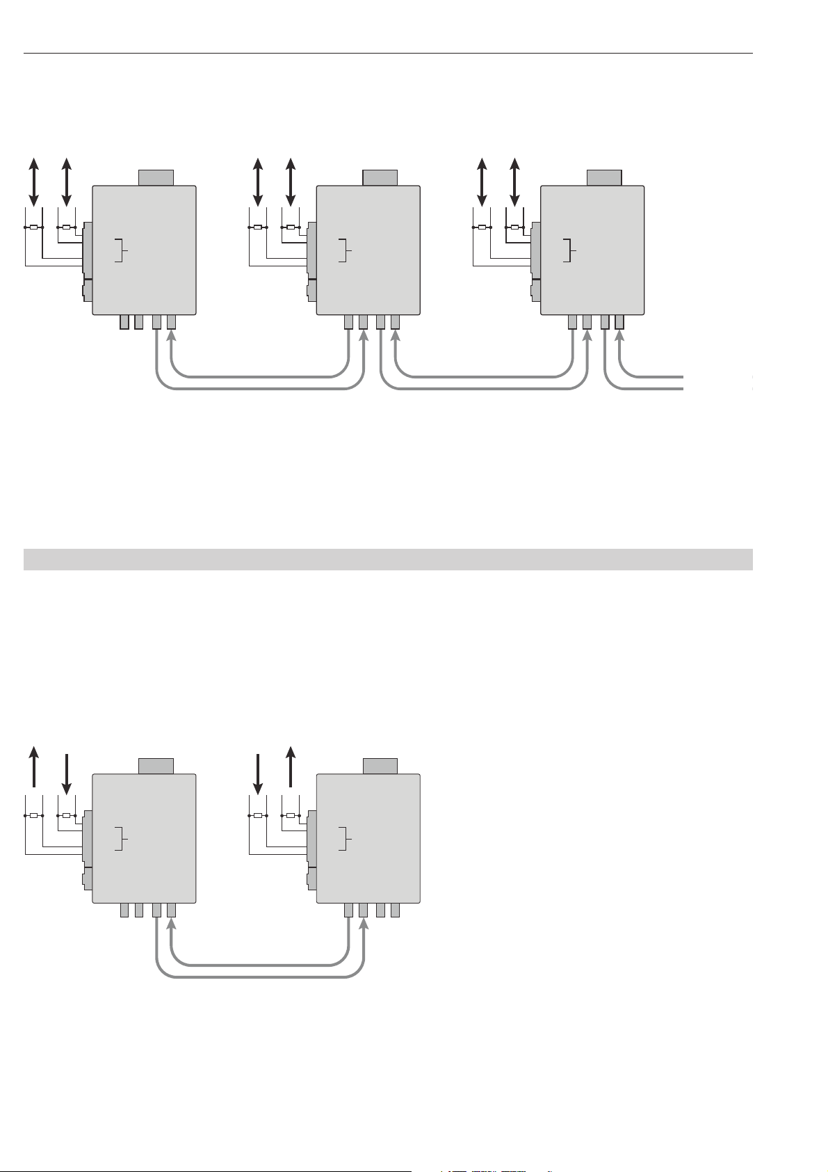
Fig. 3: Half-duplex mode – data channel K1 and data channel K2 are used for data transmission.
Data
K 2
Data
K 1
Port 1
K 1
K 2
Port 3Port 2
Data
K 2
Data
K 1
Port 1
K 1
K 2
Port 3Port 2
Data
K 2
Data
K 1
Port 1
K 1
K 2
Port 3Port 2
Fig. 4: Full-duplex mode – the data channels K1 and K2 are each used for data transmission in one direction.
Data
out
Data
in
Port 1
K 1
K 2
Port 3Port 2
DatainData
out
Port 1
K 1
K 2
Port 3Port 2
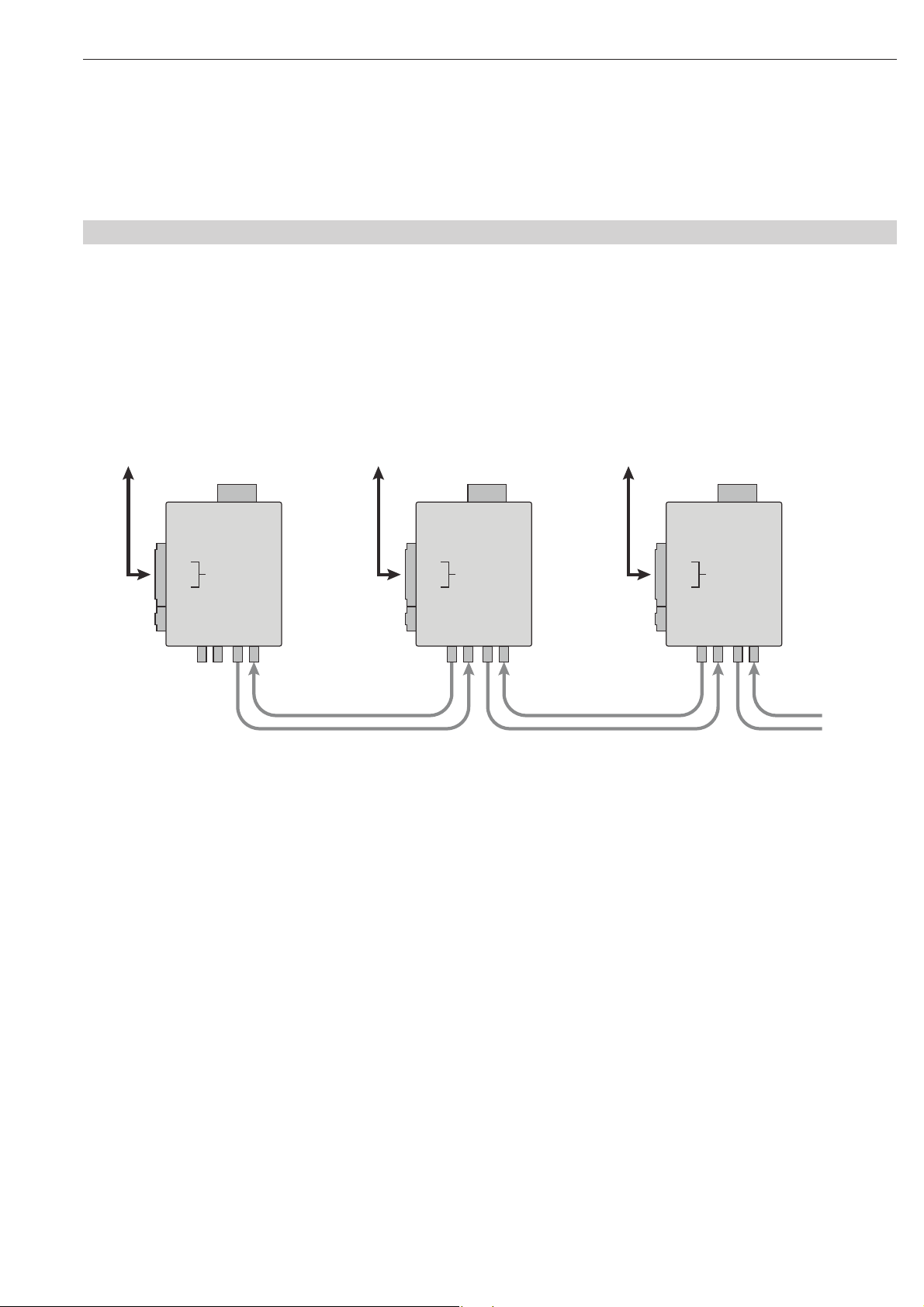
2.2 Full-duplex operation
In full-duplex mode, you can set up a bi-directional conn ection between two devices.
The data channels K1 and K2 are each used for data
transmission in one direction.
You can cascade more than two OZD 485 G12(-1300)
PRO via the optical interfaces.
The arbitration procedure used by the connected devices
must ensure that at any given time only one single bus
participant is sending on channel 1 and only one is sending on channel 2. Access methods that can cause collisions on channel 1 or channel 2 are not permissible.
3.1 Tristate recognition through permanent high
11
3 Tristate recognition
OZD 485 G12(-1300) PRO Version 04 12/2014
3 Tristate recognition
3.1 Tristate recognition through permanent high
Fig. 5: Tristate recognition through permanent high
Data
K 1
R
R
PD
R
PU
R
R
PD
R
PU
typ. 220 Ω
typ. 390 Ω
typ. 390 Ω
RT+
RT±
K1±
K1+
Port 1
K 1
K 2
Port 3Port 2
R
R
PD
R
PU
R
R
PD
R
PU
typ. 220 Ω
typ. 390 Ω
typ. 390 Ω
RT+
RT±
K1±
K1+
Port 1
K 1
K 2
Port 3Port 2
Data
K 1
One 2-wire lead , terminated by a characteristic impedence and additional pull-up/pull-down resistors, is
replaced (e.g. Modbus RTU/ASCII).
During the idle phase, a logical high level (positive volt age between terminals K1+ and K1-) is available. As
soon as a con stant high level is available for 2.5 µs,
the repeaters identify this as tristate and switch their
transmitters to the idle state (transmitter set to highresist ance).
A downward slope is identified as the start bit.
Transmission is made in the appropriate direction .
The opposite direction is disabled.
The type of tristate recognition depends on the termi nation
of the bus system used. See also chapter 5.7, page 25.

3 Tristate recognition 3.2 Tristate recognition through differential voltage
12
OZD 485 G12(-1300) PRO Version 04 12/2014
3.2 Tristate recognition through differential voltage
Fig. 6: Tristate recognition through differential voltage (INTERBUS example).
1)
INTERBUS example
Data
K 1
R
w
100 Ω
1)
K1±
K1+
1)
INTERBUS example
Data
K 1
R
w
100 Ω
1)
K1±
K1+
Port 1
K 1
K 2
Port 3Port 2
Port 1
K 1
K 2
Port 3Port 2
Fig. 7: Switching limit within which the OZD 485 G12(-1300) PRO repeaters recognize tristate (indicated in dark gray),
and the related minimum/maximum voltage valuesfor the logical conditions “high” and “low” (indicated in light gray).
– 0.7 V – 0.1 V 0.7 V0.1 V
Low Tristate High
A 2-wire lead only terminated by a characteristic
impedance is replaced.
During the idle phase, the differential voltage falls below
a certain value. The repeater recognizes this as tristate.
If a switching limit is exceeded, the t ransmission is made
in the appropriate direction . The opposite direction is disabled.
4.1 Line topology without redundancy
13
4 Network topologies
OZD 485 G12(-1300) PRO Version 04 12/2014
4 Network topologies
Fig. 8: Line topology without redundancy
Port 1
K 1
K 2
Port 3Port 2
Port 1
K 1
K 2
Port 3Port 2
Port 1
K 1
K 2
Port 3Port 2
Terminal device(s)/
bus segment
Terminal device(s)/
bus segment
Terminal device(s)/
bus segment
This network topology can be used for an optical
connection of end devices or bus segments.
For the repeaters at the end of the line, the DIL switch S3
or S4 of the related, non-occupied optical port must be
in position “1”, which means that too low incoming
power at port 2 or port 3 is not signalled at the signal
contact.
4.1 Line topology without redundancy
 Loading...