

Page 1
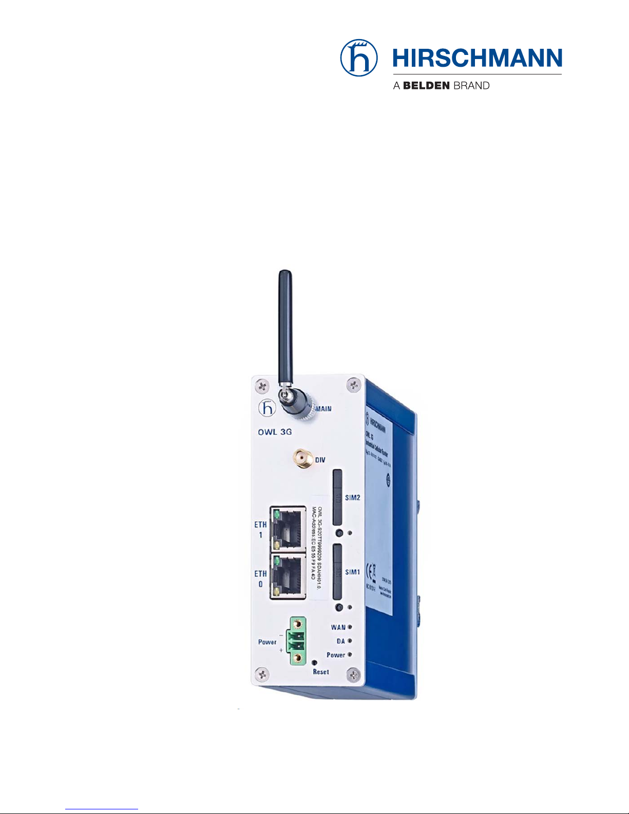
Installation OWL 3G
Release 3 06/2017
Technical Support
https://hirschmann-support.belden.eu.com
User Manual
Installation
OWL 3G (Industrial Cellular Router)
Page 2

The naming of copyrighted trademarks in this manual, even when not specially indicated, should
not be taken to mean that these names may be considered as free in the sense of the trademark
and tradename protection law and hence that they may be freely used by anyone.
© 2017 Hirschmann Automation and Control GmbH
Manuals and software are protected by copyright. All rights reserved. The copying, reproduction,
translation, conversion into any electronic medium or machine scannable form is not permitted,
either in whole or in part. An exception is the preparation of a backup copy of the software for
your own use.
The performance features described here are binding only if they have been expressly agreed
when the contract was made. This document was produced by Hirschmann Automation and
Control GmbH according to the best of the company's knowledge. Hirschmann reserves the right
to change the contents of this document without prior notice. Hirschmann can give no guarantee
in respect of the correctness or accuracy of the information in this document.
Hirschmann can accept no responsibility for damages, resulting from the use of the network
components or the associated operating software. In addition, we refer to the conditions of use
specified in the license contract.
You can get the latest version of this manual on the Internet at the Hirschmann product site
(www.hirschmann.com).
Hirschmann Automation and Control GmbH
Stuttgarter Str. 45-51
72654 Neckartenzlingen
Germany
Installation OWL 3G 12.06.2017
Page 3

Installation OWL 3G
Release 3 06/2017
3
Contents
About this Guide 5
Legend 5
GPL License 5
Safety Instructions 6
1 Router Description 10
2 Contents of Package 12
3 Router Design 13
3.1 Delivery Identification 13
3.2 Basic Dimensions of Router Box 14
3.3 Mechanical Dimensions and Mounting Recommendations 14
3.4 Removing from the DIN rail 17
3.5 Description of the Front Panel 18
3.5.1 Status Indication 19
3.5.2 Power Connector 20
3.5.3 Grounding the device (functional earth) 20
3.5.4 Antenna Connectors 21
3.5.5 SIM Card Reader 22
3.5.6 Reset 22
3.5.7 Ethernet Ports ETH0 & ETH1 23
4First Use 25
4.1 Connecting Components before the First Use 25
4.2 Start 26
4.3 Configuration 27
4.3.1 Configuration using a Web Browser 27
5 Technical Parameters 28
5.1 Basic parameters 28
5.2 Type tests and environmental conditions 28
5.3 Technical Parameters of module 29
5.4 Technical Parameters of the processor 30
6 Recommended literature 31
Page 4

4
Installation OWL 3G
Release 3 06/2017
6.1 Available Literature 31
7 Possible problems 32
7.1 Solutions 32
8FAQ 33
9 Customers Support 35
9.1 CE-marking 35
9.2 E marking 36
A Further support 37
Page 5

Installation OWL 3G
Release 3 06/2017
5
About this Guide
This document provides technical specifications for the Industrial Cellular
Router and illustrates the hardware installation for a Hirschmann Industrial
Cellular Router. It also helps the developers to validate their application
design using the Industrial Cellular Router.
The information in this publication contains general descriptions or
performance factors which, when applied in an actual situation, do not
always correspond with the described form and may be amended by way of
further development of products. The desired performance factors shall only
be deemed binding if these are expressly agreed on conclusion of the
contract. Please note that some characteristics of the recommended
accessory parts may differ from the appropriate product. This might limit the
possible operating conditions for the entire system.
Legend
The designations used in this manual have the following meanings:
GPL License
Source codes under the GPL license are available free of charge. Send an
email request to:
List
Work step
Subheading
Link Cross-reference with link
Note: A note emphasizes an important fact or draws your attention to a dependency.
Courier ASCII representation in the graphical user interface
Page 6
6
Installation OWL 3G
Release 3 06/2017
Safety Instructions
General safety instructions
You operate this device with electricity. The safe operation of the device
depends on proper handling during transportation, storage and assembly,
and proper use of operation and maintenance procedures. Improper use
of this device can cause injury or property damage.
Read this documentation, safety instructions and warnings before
connecting any cables.
Never start an operation with damaged components.
The device does not contain any service components. If the device is
not functioning correctly, or if it is damaged, turn off the power supply
and return the device to Hirschmann for inspection.
Qualification requirements for personnel
Allow only qualified personnel to work on the device who have the
following characteristics:
Properly trained personnel who have practical knowledge and
experience. This is the prerequisite for grounding and labeling
circuits, devices, and systems in accordance with current
technology safety standards.
Qualified personnel are aware of the dangers that exist in their
work.
Qualified personnel are familiar with appropriate measures against
these hazards in order to reduce the risk for themselves and others.
Qualified personnel receive training on a regular basis.
WARNING
UNCONTROLLED MACHINE ACTIONS
To avoid uncontrolled machine actions caused by data loss, configure all
the data transmission devices individually.
Before you start any machine which is controlled via data transmission, be
sure to complete the configuration of all the data transmission devices.
Failure to follow these instructions can result in death, serious injury,
or equipment damage.
Page 7

Installation OWL 3G
Release 3 06/2017
7
Intended usage
Use the product only for the application cases described in the
Hirschmann product information, including this manual.
Operate the product according to the technical parameters. See “First
Use” on page 25.
Connect components which are suitable for the requirements of the
specific application to the product.
National and international safety regulations
Verify that the electrical installation meets applicable national and
international safety regulations.
Working voltage
Connect only a working voltage that corresponds to the type plate of
your device.
Make sure the following requirements are met every time you connect
the electrical conductors:
The power supply conforms to over voltage category I or II.
The power supply has an easily accessible disconnecting device
(such as a switch or a plug) which is clearly identified. So in case
of an emergency, it is clear which disconnecting device belongs to
which power supply cable.
The electrical wires are voltage-free.
The power supply is Class 2 compliant.
The working voltage inputs are designed for operation with safety
extra-low voltage. Connect only SELV circuits with voltage
restrictions in line with IEC/EN 60950-1 to the working voltage
connections.
The wire diameter of the power supply cable is at least 0.5 mm²
(North America: AWG20) on the working voltage input.
The wire diameter of the ground conductor is at least 0.5 mm²
(North America: AWG20).
The power supply cables used are permitted for the temperature
range required by the application case.
The power cords are suitable for ambient air temperatures of at
least 167 °F (75 °C). The power cord wires are made of copper.
Turn on the operating voltage for the device only when the following
requirements are fulfilled:
The housing is closed
The terminal block is wired correctly
The terminal block for the operating supply is connected
Page 8

8
Installation OWL 3G
Release 3 06/2017
Installation site requirements
Verify that there is at least 4 in (10 cm) of space above and below the
device.
Verify that there is at least 0.8 in (2 cm) of space on the right and left
sides of the device.
Verify that there is at least a minimum distance of 20 cm between the
antenna and the human body.
Housing
Never insert pointed objects (narrow screwdrivers, wires, etc.) into the
device or into the connection terminals for electric conductors. Do not
touch the connection terminals.
Page 9

Installation OWL 3G
Release 3 06/2017
9
Please, observe the following instructions:
To prevent injury and damage to the device and to ensure that you comply
with the relevant provisions, use original accessories only. Unauthorized
modifications or unapproved utilization of accessories can result in
damage to the router and in a breach of applicable regulations.
Unauthorized modifications or unapproved utilization of accessories can
result in the termination of the guarantee.
Before handling the SIM card, disconnect the router from the power
supply.
Do not exceed the maximum voltage of 30 V DC at the power
connector of the router.
Do not expose the router to extreme ambient conditions. Protect the
router against dust, moisture and high temperature. See table 8 on
page 28.
It is recommended that you should create an appropriate copy or
backup of the important settings that are stored in the memory of the
device.
Caution! The SIM card can be swallowed by small children.
It is recommended that you do not use the router at petrol filling
stations. We recommend observing local restrictions concerning the
use of radio-based devices while working with explosive material for
example, at petrol filling stations, or in chemical plants.
While using the router close to personal medical devices, such as
cardiac pacemakers or hearing aids, proceed with heightened caution.
Note: Insert the SIM Card holder in the SIM card slot very carefully. When
inserted improperly, you can damage the SIM card slot. Also, the SIM
card can fall out of the holder and end up in the router.
Page 10

10
Installation OWL 3G
Release 3 06/2017
1 Router Description
Hirschmann has designed the OWL router for wireless communication in
mobile networks that make use of the following technologies:
HSPA+
UMTS
EDGE
GPRS
Due to the high speed data transfer, up to 14.4 Mbit/s (download) and up to
5.76 Mbit/s (upload), this router is an ideal wireless solution for connecting
the data stream and security camera systems, individual computers, LAN
networks, automatic teller machines (ATM) and other self-service terminals.
As a standard, the router is supplied in a metal casing.
The cellular router is also equipped with the following interfaces located on
the front panel:
2 Fast Ethernet 10/100BaseTX ports, RJ45
2 SIM Cards readers, for 3 V and 1.8 V SIM cards
2 SMA antenna connectors, Main + Rx Div
1 Connector (2-pin) for the power supply adapter
1 Reset button
Configuring the cellular router is possible using a graphical user interface
which is password protected. The graphical user interface provides, after
logging in, detailed statistics about the activities of the router such as, signal
strength, and a detailed system log. This device supports the creation of VPN
tunnels using technologies such as IPSec, OpenVPN and L2TP for secure
communications. The router also supports the following functions:
DHCP
NAT
DynDNS
IPSec
OpenVPN
NTP
VRRP
control by SMS
primary/backup connection
Diagnostic functions, which provide for continuous communication, include
an automatic inspection of a PPP connection, offering an automatic restart
feature in case of an unexpected termination of the connection. Another
diagnostic function is the hardware watchdog, which monitors the status of
the router.
Page 11

Installation OWL 3G
Release 3 06/2017
11
Using a special window, the start up script window, you can insert Linux
scripts for various actions. For some applications, it is crucial to create
several different configurations for a router. You can exchange these
configurations as necessary for example, using SMS. The router can
automatically upgrade a configuration and firmware from a server. This
allows you to configure several routers at a time.
Note: For the system time backup the device contains a 3 V Lithium Battery
(Li/MnO2).
Page 12
12
Installation OWL 3G
Release 3 06/2017
2 Contents of Package
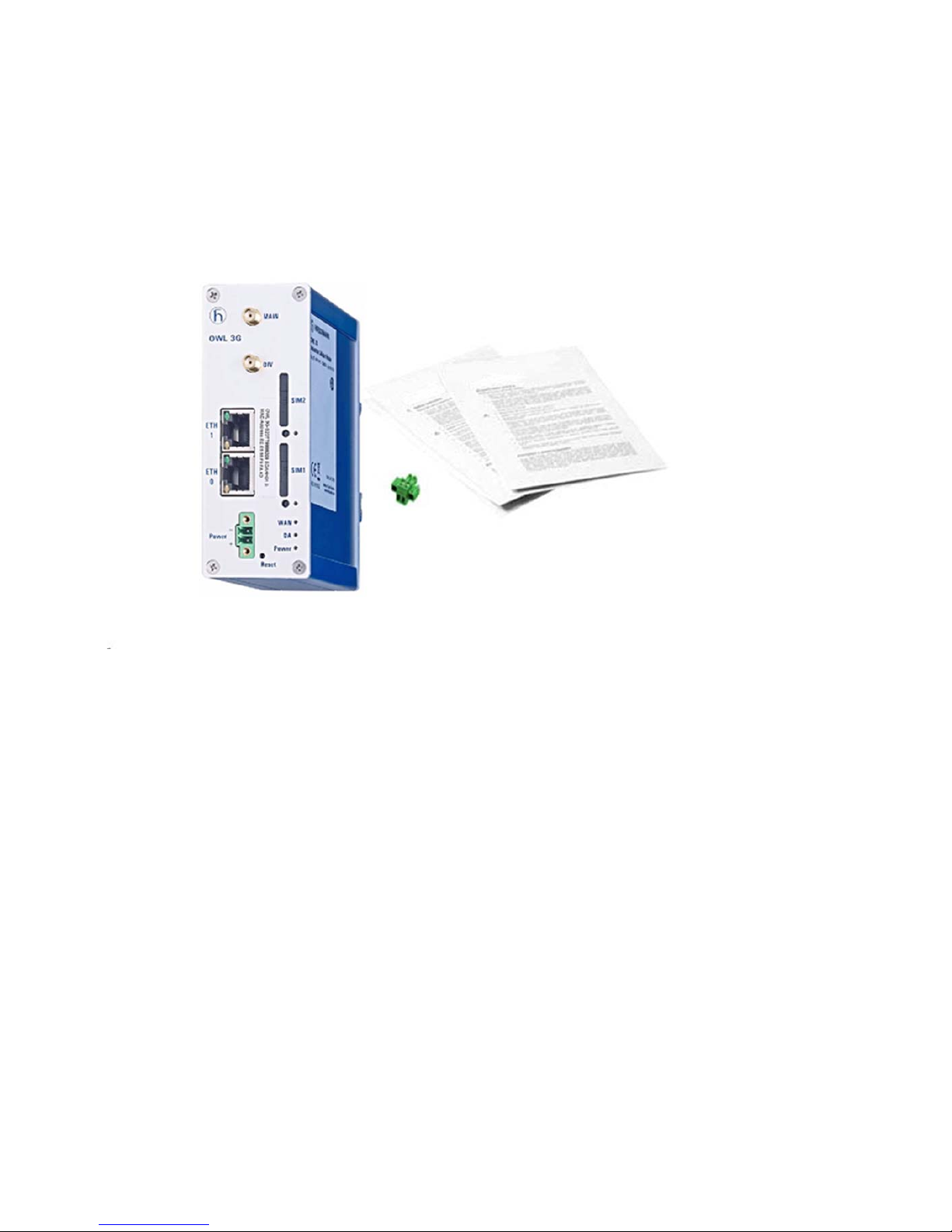
The basic router set available for delivery includes the following items:
router
clip for the DIN rail
loose power connector
General Safety Instructions
Figure 1: Contents of Package
Page 13
Installation OWL 3G
Release 3 06/2017
13
3 Router Design
3.1 Delivery Identification
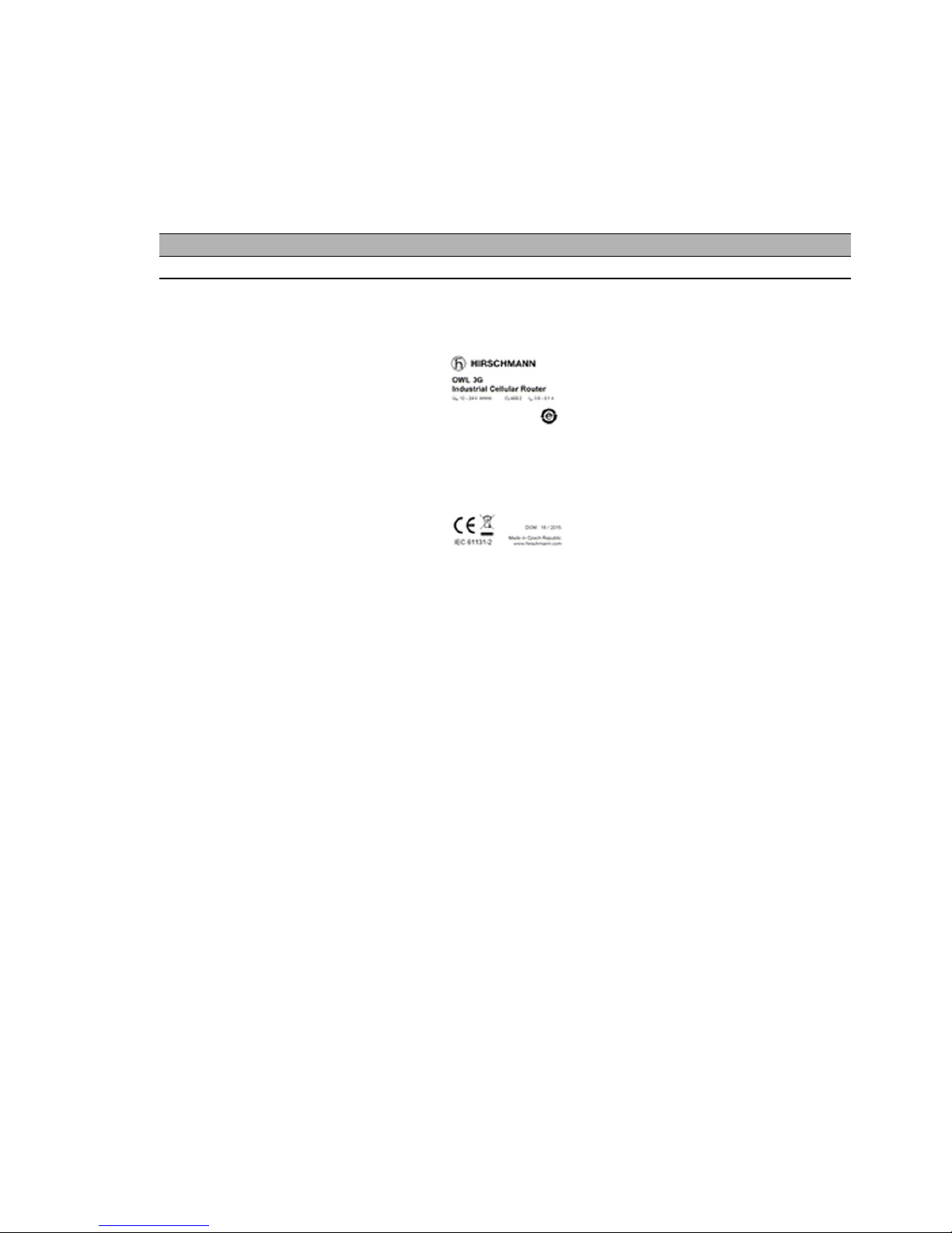
Figure 2: Example of Router Label
Product Name Product Code Product Group
OWL 3G OWL 3G-S20TT9999209SDAHHXX.X Industrial Cellular Router
Table 1: Delivery identification
Page 14

14
Installation OWL 3G
Release 3 06/2017
3.2 Basic Dimensions of Router Box
Figure 3: Basic Dimensions of Router Case
3.3 Mechanical Dimensions and Mounting
Recommendations
Mounting recommendations:
place router on a work surface
DIN rail with the CKD2 holder included
Page 15

Installation OWL 3G
Release 3 06/2017
15
Figure 4: Space around antennas
We recommend you bind every cable in a bunch according to the following
figure. For this use we recommend you observe the following rules:
The length of the combination of power supply and data cables can be a
maximum of 1.5 m. If the length of data cables or power cable exceeds
1.5 m, we recommend that you install surge protectors.
Do not use data cables which conduct working voltage 230 V/50 Hz.
Use twisted pair cables for sensor communications.
Figure 5: Cable routing
Sufficient space must be left before individual connectors for handling of the
cables:
Page 16

16
Installation OWL 3G
Release 3 06/2017
Figure 6: Space in front of connectors
For the correct function of the router, use earth-bonding distribution frame for
grounding of power supply of router, data cables and antenna.
Page 17

Installation OWL 3G
Release 3 06/2017
17
3.4 Removing from the DIN rail
Default position of holder, used for mounting the router on a DIN rail, is
shown in the following figure:
Figure 7: Default position of DIN holder
To remove the router from the DIN rail, it is necessary to lightly push the
router downward so that the bottom part of the holder clears the rail. After the
holder clears the rail rotate the bottom part of the router out away from the
DIN rail.
Figure 8: Removing from the DIN rail
Page 18

18
Installation OWL 3G
Release 3 06/2017
3.5 Description of the Front Panel
The front panel of router contains the following connectors:
Figure 9: Router Front Panel
Caption Connector Description
Power 2-pin Connector for the power supply adapter
ETH0 RJ45 Connector for connection into the local computer network
ETH1 RJ45 Connector for connection into the local computer network
MAIN SMA Connector for main antenna
DIV SMA Connector for diversity antenna
SIM1 - Holder for the first SIM card
SIM2 - Holder for the second SIM card
Reset - Returns the configuration in the router to the default settings.
Table 2: Delivery identification
Page 19

Installation OWL 3G
Release 3 06/2017
19
3.5.1 Status Indication
There are 3 LED indicators on the front panel and 2 LED indicators on every
port, that provide information about the port status.
Applies to software releases before 01.2.01 (2017-01-06):
Applies to software releases from 01.2.01 (2017-01-06):
Caption Color State Description
Power Green Blinking
On
Fast blinking
Router is ready
Starting of the router
Updating firmware
WAN
a
a. The WAN status is updated every 10 seconds. The WAN LED displays the current status.
Yellow 1x flash per sec.
2x flash per sec.
3x flash per sec.
Signal strength is from -50 dBm to -69 dBm
Signal strength is from -70 dBm to -89 dBm or
difference between neighbors cells is exactly 3 dBm
Signal strength is from -90 dBm to -113 dBm or
difference between neighbors cells is smaller than 3
dBm
DA Red Blinking Communication in progress on radio channel
ETH0
ETH1
Green On
Off
Selected 100 Mbit/s
Selected 10 Mbit/s
ETH0
ETH1
Yellow On
Blinking
Off
The network cable is connected
Data transmission
The network cable is not connected
SIM1 Yellow On SIM card 1 is active
SIM2 Yellow On SIM card 2 is active
Table 3: Router Status Indication
Caption Color State Description
Power Green On
Blinking
Fast blinking
Router is ready
Starting of the router
Updating firmware
WAN
a
Yellow 1x flash per sec.
2x flash per sec.
3x flash per sec.
Signal strength is from -50 dBm to -69 dBm
Signal strength is from -70 dBm to -89 dBm or
difference between neighbors cells is exactly 3 dBm
Signal strength is from -90 dBm to -113 dBm or
difference between neighbors cells is smaller than 3
dBm
DA Red Blinking Communication in progress on radio channel
ETH0
ETH1
Green On
Off
Selected 100 Mbit/s
Selected 10 Mbit/s
ETH0
ETH1
Yellow On
Blinking
Off
The network cable is connected
Data transmission
The network cable is not connected
Table 4: Router Status Indication
Page 20

20
Installation OWL 3G
Release 3 06/2017
3.5.2 Power Connector
Panel socket 2-pin.
Figure 10: Power connector
The power supply for the router should be between +12 V to +24 V DC
supply. Protection against reversed polarity without signaling is built into the
router.
The power consumption during receiving is 2.3 W. The peak power
consumption during data sending is 5.5 W. For correct operation, it is
necessary that the power source is able to supply a peak current of 0.9 A.
Circuit example:
Figure 11: Power connector pin-outs
3.5.3 Grounding the device (functional earth)
Ground the device by connecting the minus pole (GND) of the power supply
to earth. When you mount the device on a grounded DIN rail, then the DIN
rail provides the ground.The shield of a shielded twisted pair cable is
connected to the housing and the minus pole of the power supply socket.
SIM1 Yellow On SIM card 1 is active
SIM2 Yellow On SIM card 2 is active
a. The WAN status is updated every 10 seconds. The WAN LED displays the current status.
Pin number Signal mark Description
1 VCC(+) Positive pole of DC supply voltage (+12 to +24 V DC)
2 GND(-) Negative pole of DC supply voltage (connected to ground)
Table 5: Connection of Power Connector
Caption Color State Description
Table 4: Router Status Indication
Page 21

Installation OWL 3G
Release 3 06/2017
21
3.5.4 Antenna Connectors
Main and diversity antennas are connected to the router using the SMA
connector on the front panel. The "MAIN" connector is used to connect the
main antenna to the router. To connect the diversity antenna, use the second
"DIV" antenna connector.
Note: Do not operate the router without the main antenna connected.
For connecting the antenna, use an SMA connector. Screw the antennas to
the SMA connector on the front panel of the router (see figure below).
Note: Be very careful when tightening the antenna. If you over tighten the
antenna, then you will twist the antenna connector off of the circuit board.
Figure 12: Connecting the Antenna
The diversity antenna improves radio features of the router at a low signal
strength.
Page 22

22
Installation OWL 3G
Release 3 06/2017
3.5.5 SIM Card Reader
There are 2 SIM card readers for 3 V and 1.8 V SIM cards located on the front
panel of the router.
In order for the router to function properly, insert an activated SIM card with
the PIN code unblocked in to the SIM card holder. Each SIM card can have
a different APN (Access Point Name).
Note: When changing the SIM Card, pay close attention to the following
rules:
Before handling the SIM card, disconnect the router from the power
supply.
Press the small button under the SIM card slot to eject the SIM card
holder.
Remove the SIM card and place another SIM card into the holder.
Very carefully, insert the SIM card holder and SIM card in the slot. Push
the SIM card holder into the slot until it clicks in place.
Figure 13: Example of an ejected SIM card holder
3.5.6 Reset
When the "Power" LED on the front panel has turned on, it is possible to
restore the default configuration of the router by pressing the "Reset" button.
After pressing the "Reset" button, the default configuration is restored and
the router reboots. During rebooting, the "Power" LED blinks.
Note: We recommend that you back up the router configuration before
resetting the router. For detailed information about resetting the router refer
to the User Manual Configuration. Resetting the router returns the
configuration to the default state.
Use a narrow screwdriver for pressing the "Reset" button located on the front
panel.
Page 23

Installation OWL 3G
Release 3 06/2017
23
Figure 14: Router Reset
It is important to distinguish the difference between resetting and rebooting
the router.
3.5.7 Ethernet Ports ETH0 & ETH1
Panel socket RJ45.
Action Router behavior Invoking events
Reboot Turn off and then turn on router. Disconnect and connect the power.
Reset Restore default configuration and reboot
the router
Press "Reset" button on front panel
Table 6: Description of Reset and Restart Router
Pin Signal mark Description Data flow direction
1 TXD+ Transmit Data - positive pole Input/Output
2 TXD- Transmit Data - negative pole Input/Output
3 RXD+ Receive Data - positive pole Input/Output
4- 5- 6 RXD- Receive Data - negative pole Input/Output
7- 8- -
Table 7: Ethernet connector pin-outs
Page 24

24
Installation OWL 3G
Release 3 06/2017
Figure 15: Ethernet Connector
Note: ETH0 and ETH1 ports are not POE (Power Over Ethernet) compatible.
Ethernet cable plugged into the RJ45 connector is labeled as ETH0 or ETH1
(see figure below).
Figure 16: Connection of an Ethernet Cable
Page 25

Installation OWL 3G
Release 3 06/2017
25
4First Use
4.1 Connecting Components before the First
Use
Before putting the router into operation, it is necessary to connect the
components which are required for your applications. Do not forget to insert
at least 1 SIM card.
Note: The router can not operate without connecting the main antenna, at
least 1 SIM card and a power supply. If the antenna is not connected, the
router can be damaged.
Note: Be very careful when tightening the antenna. If you over tighten the
antenna, then you can twist the antenna connector off of the circuit board.
Page 26

26
Installation OWL 3G
Release 3 06/2017
Figure 17: Router Connection
4.2 Start
The router operates when the power supply is connected to the router. By
default, the router automatically starts to log in to the default APN. You can
change the parameters of the router behavior using the web interface. You
can find a detailed description of the parameters in the User Manual
Configuration.
Page 27

Installation OWL 3G
Release 3 06/2017
27
The power consumption during receiving is 2.3 W. The peak power
consumption during data sending is 5.5 W. For correct operation, it is
necessary that the power source supplies a peak current of 0.9 A.
4.3 Configuration
Note: Before you apply power to the router, insert at least 1 SIM card in the
router, and install the main antenna. Activate the SIM card in the
"Administration> Unlock SIM card" dialog, after inserting it into the SIM card
reader.
4.3.1 Configuration using a Web Browser
Status monitoring, configuration and administration of the router is available
using the graphical user interface (GUI) which can be accessed by entering
the IP address of the router into your web browser. The default IP address of
the router is 192.168.1.1 netmask 255.255.255.0. The default settings allow
only the user admin with the default password private to configure the
router.
Note: Use the HTTPS protocol for secure communication.
After successfully entering the login information a user has access to the
router using the Internet browser.
Page 28

28
Installation OWL 3G
Release 3 06/2017
5 Technical Parameters
5.1 Basic parameters
5.2 Type tests and environmental conditions
OWL 3G
Complies with standards EN 301 511, EN 300 440-2
EN 301 908-1, -2, -13
EN 301 489-1, -7, -24
EN 60950-1, EN 62311
EN 61000-6-2
EN 61131-2
EN 55022
Temperature
range
Operation -40°C to +70°C
Storage -40°C to +85°C
Cold start -35 °C
-40 °C
Data transfers via mobile network are available immediately
Data transfers via mobile network are available approximately
in five minutes after the start of the router. Everything else is
functional immediately.
Humidity Operating
Storage
0 to 95 % relative humidity non condensing
0 to 95 % relative humidity non condensing
Altitude Operating 2000 m/ 70 kPa
Protection IP30
Supply voltage 12 to 24 V DC
Consumption Reception
GPRS
UMTS
2.3 W
to 3.5 W (GPRS transmission)
to 5.5 W (UMTS/HSDPA transmission)
Dimensions 42 x 87 x 113 mm (DIN 35 mm)
Weight 280 g
Antenna connectors SMA - 50 Ohm
Use interfaces 2x ETH Ethernet (10/100 Mbit/s)
Table 8: Technical Parameters of the Router
Phenomena Test Description Test levels
ESD EN 61000-4-2 Enclosure contact
Enclosure air
± 6 kV
± 8 kV
RF field AM modulated IEC 61000-4-3 Enclosure 10 V/m
(80 – 2700 MHz)
Fast transient EN 61000-4-4 Signal ports
Power ports
Ethernet ports
± 2 kV
± 2 kV
± 2 kV
Table 9: Type tests and environmental conditions
Page 29

Installation OWL 3G
Release 3 06/2017
29
5.3 Technical Parameters of module
Depending on the capabilities of the operator.
Surge EN 61000-4-5 Ethernet ports
Power ports
I/O ports
± 2 kV, shielded cable
± 0,5 kV
± 1 kV, L to L
± 2 kV, L to GND
RF conducted EN 61000-4-6 All ports 10 V/m
(0,15 – 80 MHz)
Radiated emission EN 55022 Enclosure Class B
Conducted emission EN 55022 DC power ports
Ethernet ports
Class B
Class B
Dry heat EN 60068-2-2 +75 C, 40 % rel. humidity
Cold EN 60068-2-1 -40 C
Damp heat EN 60068-2-78 95% rel. humidity (+40 C)
HSPA+ module
HSPA+ parameters Bit rate 14.4 Mbps (DL) / 5.76 Mbps (UL)
3GPP rel. 6/7 standard
Data compress 3GPP
UMTS parameters Bit rate 384 kbps (DL) / 384 kbps (UL)
3GPP rel. 4 standard
GPRS/EDGE parameters EDGE bit rate 237 kbps (DL) / 237 kbps (UL)
GPRS bit rate 85.6 kbps (DL) / 85.6 kbps (UL)
Multi slot class 12, CS 1 to 4, 3GPP rel. 99/4 standard
Support channels GSM/GPRS/EDGE: Quad band,
850/900/1800/1900 MHz
UMTS/HSDPA/HSUPA/HSPA+: Five band,
800/850/900/1900/2100 MHz
Table 10: Technical parameters of the module
Phenomena Test Description Test levels
Table 9: Type tests and environmental conditions
Page 30

30
Installation OWL 3G
Release 3 06/2017
5.4 Technical Parameters of the processor
32b ARM microprocessor
Memory 512 Mb DDR SDRAM
128 Mb FLASH
1 Mb MRAM
Interface Serial interface RS232
Ethernet interface 10/100 Mbit/s
USB 2.0 interface
Table 11: Technical Parameters of the processor
Page 31

Installation OWL 3G
Release 3 06/2017
31
6 Recommended literature
6.1 Available Literature
User Manual Configuration
Page 32

32
Installation OWL 3G
Release 3 06/2017
7 Possible problems
7.1 Solutions
Some network cards are able to be set in a situation, when it is not possible
to connect directly to the router. Follow the steps below to solve this problem:
manually select the
10 Mb/s
communication rate for the network card
connect the computer to the router through a switch
start the computer only after the router has completed its boot process
Page 33

Installation OWL 3G
Release 3 06/2017
33
8FAQ
When I have NAT enabled, I can’t access the equipment from the internet,
which is connected to the router.
– Configure the gateway in the device with the IP address of the router.
The router resets itself and the Ethernet connection fails.
– Connect an antenna to the router. Keep the antenna as far as possible
away from the power supply.
I cannot get on the web server at NAT.
– The remote http access of the router has to be disabled, default server
address has to be your web server and the gateway of the web server
has to be the IP of router.
PPP connection fails.
– Check the signal power. If the signal power is weak, then use a better
antenna. If the neighboring cells have a similar signal strength, then
use a directional antenna. For proper operation, the signal levels have
to be in the range from - 50dBm through -90dBm.
– Configure the router to ping the neighbors. The router verifies the
connection using the ping function. When the ping fails, the router
attempts to re-establish the connection.
The router can not establish the PPP connection.
– Recheck GPRS settings – APN, name, password and IP address.
– Try to enter the PIN – verification if the SIM card has the PIN code set.
– In private APN, disable the DNS server.
– Enable the system log and observe where the router detected errors.
Connection fails on Ethernet or connection not established.
– It is possible to disable the auto negotiation and set a rate and duplex
manually on the Ethernet interface of the router.
DynDNS is not functioning.
– In a private APN, the DynDNS function is unavailable.
– If the same IP address is recorded in your canonic name as a
dynamically assign address, it means that the operator is using NAT
or firewall.
– To verify NAT, ping the static server address.
– Verify Firewall accessing remotely to the GUI interface of the router.
– The operator does not give out the address of DNS servers and
without the address of the DNS servers, it is impossible to connect to
the dyndns.org server. The router displays the following messages in
the log system:
– DynDNS daemon started
– Error resolving hostname: no such file or directory
– Connect to DynDNS server failed
Page 34

34
Installation OWL 3G
Release 3 06/2017
IPSec tunnel is established but communication does not function.
– Verify that you have specified the route conditionals of connected
equipment correctly. Also verify the Gateway configuration.
FTP does not function.
– Router does not support the active FTP mode, supports the passive
mode only.
L2TP or IPSec is not established.
– Verify the reason in the log system.
I switched the router to the off line mode using an SMS message, but the
router is in the online mode after restart.
– The control SMS message does not change the router configuration.
For example, if the router is changed to the off line mode using an SMS
message, then the router remains in this mode until the next restart.
This behavior is the same for every control SMS message.
Page 35

Installation OWL 3G
Release 3 06/2017
35
9 Customers Support
You can find current information about this product on our website:
http://www.hirschmann.com/en/QR/OWL-Industrial-Cellular-Routers
Upkeep-advices:
– The SIM card must be handled carefully like a credit card. Do not bend or
scratch the SIM card and do not expose the SIM card to static electricity.
– When cleaning the router, do not use aggressive chemicals, solvents or
abrasive cleaners.
The router meets the SAR coefficient values defined by the International
Commission on Non-Ionizing Radiation (ICNIRP) and the values described
in "About protection of health before non-ionized radiation".
9.1 CE-marking
Hirschmann hereby declares that the labeled devices comply with the
regulations contained in the following European directives:
2011/65/EU (RoHS)
Directive of the European Parliament and of the Council on the restriction
of the use of certain hazardous substances in electrical and electronic
equipment.
2014/53/EU (RED)
Directive of the European Parliament and of the council on the
harmonization of the laws of the Member States relating to the making
available on the market of radio equipment.
This product may be operated in all EU (European Union) countries.
In accordance with the above-named EU directives, the EU declaration of
conformity will be at the disposal of the relevant authorities at the following
address:
Hirschmann Automation and Control GmbH
Stuttgarter Str. 45-51
72654 Neckartenzlingen
Germany
The product can be used in industrial areas only.
Warning! This is a class A device. This device can cause interference in
living areas, and in this case the operator may be required to take
appropriate measures.
Page 36

36
Installation OWL 3G
Release 3 06/2017
Note: The assembly guidelines provided in these instructions must be
strictly adhered to in order to observe the EMC threshold values.
9.2 E marking
The labeled devices comply with the regulations contained in the following
European directive(s):
Regulation No. 10 of the Economic Commission for Europe of the United
Nations (UN/ECE): Devices with an approval are labeled with the
E type approval mark.
Page 37

Installation OWL 3G
Release 3 06/2017
37
A Further support
Technical questions
For technical questions, please contact any Hirschmann dealer in your area
or Hirschmann directly.
You find the addresses of our partners on the Internet at
http://www.hirschmann.com.
A list of local telephone numbers and email addresses for technical support
directly from Hirschmann is available at
https://hirschmann-support.belden.eu.com.
This site also includes a free of charge knowledge base and a software
download section.
Hirschmann Competence Center
The Hirschmann Competence Center is ahead of its competitors on three
counts with its complete range of innovative services:
Consulting incorporates comprehensive technical advice, from system
evaluation through network planning to project planning.
Training offers you an introduction to the basics, product briefing and user
training with certification.
You find the training courses on technology and products currently
available at http://www.hicomcenter.com.
Support ranges from the first installation through the standby service to
maintenance concepts.
With the Hirschmann Competence Center, you decided against making any
compromises. Our client-customized package leaves you free to choose the
service components you want to use.
Internet:
http://www.hicomcenter.com
Page 38

 Loading...