

Page 1
Bedienungsanleitung
Bitte genau durchlesen!
Instruction manual
Please read before use!
Hirschmann Laborgeräte GmbH & Co. KG
Hauptstraße 7–15 • 74246 Eberstadt Germany
Fon +49 7134 511-0 • Fax +49 7134 511-990
www.hirschmannlab.com • [email protected]
opus® titration
Elektronisches Titrieren
Electronical titration
X2120441000
1
Page 2

Inhalt
Seite
1. Warn- und Sicherheitsvorschriften ..............................................5
2. Einzelteile .....................................................................................9
3. Funktionsübersicht .....................................................................10
4. Einsatzverbote ............................................................................12
5. Einsatzbeschränkungen ..............................................................13
6. Gerät vorbereiten .......................................................................14
6.1 Einsetzen des Lichtschutzfensters .............................................15
6.2 Befestigung Ansaugschlauch .....................................................16
6.3 Befestigung Rückführschlauch ..................................................17
6.4 Befestigung Ausstoßeinheit .......................................................17
6.5 Gerät auf Flasche schrauben .....................................................18
6.6 Ausstoßeinheit in gewünschte Position drehen .......................19
6.7 Gerät zum Flaschenetikett ausrichten .......................................19
6.8 Akku Einbau (optional) ...............................................................20
6.9 Akku laden (optional) ................................................................21
7. Arbeitsbeginn .............................................................................22
7.1 Symbolübersicht .........................................................................23
7.2 Gerät ein-/ausschalten ...............................................................24
7.3 LED Status ...................................................................................26
7.4 Wahl der Dezimalstellen (10 ml) ...............................................26
7.4.1 Dezimalstellen der Volumenanzeige ändern ............................27
7.5 Verschlusskappe abnehmen ......................................................27
7.6 Entlüften des Geräts...................................................................28
8. Titrieren ......................................................................................29
8.1 Befüllen ......................................................................................30
8.2 Einstellen der Ansaug- bzw. Ausstoßgeschwindigkeit ..............32
Contents
Page
1. Warning and safety instructions ..................................................5
2. Individual components ................................................................9
3. Function overview ......................................................................10
4. Prohibited use ............................................................................12
5. Restrictions on use .....................................................................13
6. Preparing the unit ...................................................................... 14
6.1 Using the UV protection window ...............................................15
6.2 Securing the suction hose .........................................................16
6.3 Securing the recirculation hose .................................................17
6.4 Securing the ejection unit .........................................................17
6.5 Screwing the unit onto the bottle .............................................18
6.6 Turning the ejection unit to the correct position ......................19
6.7 Bottle label aligning unit ...........................................................19
6.8 Battery installation (optional) ....................................................20
6.9 Battery charging (optional) .......................................................21
7. Start of work ..............................................................................22
7.1 Overview of symbols .................................................................23
7.2 Activating/deactivating the unit ................................................24
7.3 LED status ................................................................................... 26
7.4 Modification of decimal places (10 ml) ....................................26
Modify displayed decimal places ...............................................27
7.4.1
7.5 Closure cap removal ................................................................... 27
7.6 Venting the unit .........................................................................28
8. Titration ......................................................................................29
8.1 Filling ......................................................................................... 30
8.2 Configuring of suctioning and ejection speed ......................... 32
2
Page 3

Inhalt
Seite
8.3 Schnelltitration ...........................................................................33
8.4 Tropfentitration...........................................................................35
8.5 Clear ............................................................................................36
9. Sonderfunktionen ......................................................................37
9.1 Hauptbildschirm ..........................................................................37
9.2 Sprachwahl .................................................................................38
9.3 Quick-Cal .....................................................................................38
9.4 PIN-Schutzfunktion.....................................................................40
9.4.1 PIN-Schutz aktivieren .................................................................40
9.4.2 PIN-Schutz deaktivieren.............................................................41
9.4.3 Eingeschränkte Benutzer-PIN aktivieren ...................................41
9.4.4 Eingeschränkten Benutzermodus deaktivieren ........................43
9.4.5 PIN vergessen ............................................................................43
9.5 Methode speichern ....................................................................44
9.6 Methode abrufen ........................................................................45
9.7 Taster ..........................................................................................46
9.8 Info ..............................................................................................47
10. Schnittstelle ................................................................................48
11. Reinigen ......................................................................................48
11.1 Wartung/Reinigung ....................................................................50
11.2 Grundreinigung mittels Funktion Entlüften ...............................51
11.3 Intensivreinigung .......................................................................52
12. Sterilisation.................................................................................55
12.1 Vorbereitung ...............................................................................56
12.2 Demontage .................................................................................56
12.3 Ansaug-, Ausstoß- und Rückführventil lockern .........................57
Contents
Page
8.3 Rapid titration ............................................................................ 33
8.4 Droplet titration .......................................................................... 35
8.5 Clear ............................................................................................36
9. Special functions ........................................................................37
9.1 Main screen ................................................................................37
9.2 Language selection .................................................................... 38
9.3 Quick-Cal .....................................................................................38
9.4 PIN Protection ............................................................................40
9.4.1 Activate PIN protection ..............................................................40
9.4.2 Deactivation of the PIN ..............................................................41
9.4.3 Activation of restricted user PIN ...............................................41
9.4.4 Deactivation of restricted user mode ........................................43
9.4.5 If the PIN is forgotten ................................................................43
9.5 Method saving............................................................................44
9.6 Activating the method ...............................................................45
9.7 Switches .....................................................................................46
9.8 Info..............................................................................................47
11. Interface .....................................................................................48
11. Cleaning ......................................................................................48
11.1 Service/Cleaning ........................................................................50
11.2 Basic cleaning with the venting function .................................51
11.3 Intensive cleaning ......................................................................52
12. Sterilisation.................................................................................55
12.1 Preparation .................................................................................56
12.2 Dismantling ................................................................................56
12.3 Loosening the suction, ejection and recirculation valve ..........57
3
Page 4

Inhalt
Seite
12.4 Sterilisation durchführen ............................................................60
12.5 Montage .....................................................................................61
12.6 Ansaug-, Ausstoß- und Rückführventil festdrehen ...................62
12.7 Funktionsprüfung .......................................................................63
13. Ventile auswechseln ..................................................................64
13.1 Ansaugventil auswechseln ........................................................ 64
13.2 Ausstoßventil auswechseln ....................................................... 65
13.3 Rückführventil auswechseln ......................................................65
14. Reparatur beim Hersteller..........................................................66
15. Volumenprüfung ......................................................................... 66
16. Problembehandlung ...................................................................70
16.1 Meldungen .................................................................................70
16.2 Sonstige Probleme - Lösungen ..................................................74
16.3 Herstellerkontakt .......................................................................80
17. Technische Daten ......................................................................81
18. Material ......................................................................................85
19. Zubehör und Ersatzteile ............................................................ 86
20. Vordruck der Unbedenklichkeitsbescheinigung .......................87
Contents
Page
12.4 Sterilisation procedure ...............................................................60
12.5 Assembly ....................................................................................61
12.6 Tightening the suction, ejection and recirculation valve..........62
12.7 Function inspection .................................................................... 63
13. Valve replacement .....................................................................64
13.1 Suction valve replacement ........................................................64
13.2 Ejection valve replacement .......................................................65
13.3 Recirculation valve replacement ...............................................65
14. Repair by manufacturer .............................................................66
15. Volumetric inspection.................................................................66
16. Touble-shooting .........................................................................72
16.1 Messages ....................................................................................72
16.2 Other problems - solutions ........................................................77
16.3 Contacting the manufacturer .....................................................80
17. Technical data .............................................................................83
18. Material ......................................................................................85
19. Accessories and spare parts ...................................................... 86
20. Clearance certificate form ..........................................................88
4
Page 5

1. Warn- und Sicherheitsvorschriften
1. Warning and safety instructions
Achtung!
Vor Gebrauch des Gerätes die Bedienungsanleitung
und die Sicherheitsvorschriften beachten. Jeder im
Labor beschäftigen Person sind diese Sicherheitshinweise vor Benutzung bekannt zu machen und
jederzeit griffbereit zu halten. Die Gebrauchsanleitung
ist jedoch nicht in der Lage, alle auftretenden
Sicherheitsprobleme darzustellen. Jeder Anwender
ist selbst verantwortlich, Sicherheits- und Gesundheitsvorschriften einzuhalten und Einschränkungen vor
Gebrauch des Gerätes zu bestimmen und zu beachten.
- Beachten Sie sämtliche allgemeine Sicherheitsvorschriften für das Labor, wie z. B. das Tragen von Schutzkleidung, Schutzbrille und Schutzhandschuhen beim
Einsatz entsprechender Flüssigkeiten.
Warning!
Read the instruction manual prior to using the unit and
observe all safety instructions. Any person working in
the laboratory should be familiar with these safety
instructions prior to using the unit, and the safety
instructions should be accessible at all times. However,
the instruction manual cannot illustrate every safety problem
which may occur. Every user is personally responsible
for observing the safety and health protection regulations
and determining restrictions prior to using the unit.
These restrictions should then be observed.
- Observe all general safety instructions for the laboratory
e. g. wearing of protective clothing, safety glasses and
protective gloves when using certain liquids.
5
Page 6

1. Warn- und Sicherheitsvorschriften
- Beachten Sie die Hinweise und Vorschriften der Reagenzhersteller.
1. Warning and safety instructions
- Observe the instructions and regulations of reagent
manufacturers.
- Das Gerät darf nur zum Titrieren von Flüssigkeiten eingesetzt werden, wobei definierte Einsatzverbote und
Einsatzbeschränkungen unbedingt einzuhalten sind
(ggf. Rücksprache beim Hersteller).
- Vor Gebrauch jeweils Dichtigkeit aller Verbindungen und
sicheren Sitz der Ausstoßeinheit und des Ansaugschlauches
überprüfen. Eine nicht festsitzende Austoßeinheit könnte
beim Herunterfahren der Kolbeneinheit Spritzer verursachen.
- Vor dem Titrieren unbedingt die Verschlusskappe vom
Ausstoßschlauch nehmen. Niemals das Gerät in Funktion
setzen, solange die Verschlusskappe aufgesetzt ist.
- Achten Sie darauf, dass weder Sie selbst noch eine andere
Person gefährdet werden. Nie in Richtung einer Person
arbeiten, Spritzer vermeiden, geeignete Aufnahmegefäße
verwenden. Titrieren Sie jeweils an die Innenwand des
Aufnahmegefäßes anstatt auf dessen Inhalt oder Boden.
- The unit should only be used for titrating liquids, and it
is imperative that usage prohibitions and restrictions be
observed (consult the manufacturer if necessary).
- Prior to use, check all connections for leaks and ensure
that the ejection unit and suction hose are securely
fitted. A loosely-fitted ejection unit could cause splashing
when the piston unit is lowered.
- It is imperative that the closure cap should be removed
from the ejection hose prior to titrating.
Never activate the unit while the closure cap is fitted.
- Ensure that neither you yourself nor other persons are
at risk. Never work facing in the direction of another
person. Avoid splashing and use suitable collecting
vessels. Always titrate onto the interior wall of the
collecting vessel rather than directly onto its base or the
contents contained therein.
6
Page 7

1. Warn- und Sicherheitsvorschriften
1. Warning and safety instructions
- Keinesfalls Gewalt anwenden!
- Nach Gebrauch den Ausstoßschlauch mit der Verschluss kappe verschließen. Vorsicht! Reagenz kann heraustropfen!
- Nur Original-Zubehör und Original-Ersatzteile verwenden.
- Nach der Sterilisation (siehe Punkt 12) die Teile auf
Raumtemperatur abkühlen lassen.
- Bei Störungen, z. B.
- schwergängige oder festsitzende Kolbeneinheit
- verklebtes oder undichtes Ansaug-, Ausstoß- oder
Rückführventil
- undichte Stellen
- Bruch von Bauteilen
sofort aufhören zu arbeiten. Vor weiterer Benutzung
des Gerätes die Hinweise zur Reinigung (siehe Punkt
11) und Problemlösungen (siehe Punkt 16) beachten.
Ggf. zur Reparatur an Hersteller senden. Beachten Sie
hierzu Punkt 14!
- Never use force!
- Seal the ejection hose with the closure cap after use.
Caution! Reagent can drop out!
- Use only original accessories and original spare parts.
- Allow components to cool to room temperature after
sterilisation (see point 12).
- ln case of malfunction, e. g.
- piston unit stiffness or seizure
- sticky or leaking suction, ejection or recirculation
valve
- leaks
- component breakage
stop working immediately. Observe the instructions on
cleaning (see point 11) and problem solutions (see
point 16) before continuing to use the unit. Send to
manufacturer for repair if necessary. Observe point
14 in this respect!
7
Page 8

1. Warn- und Sicherheitsvorschriften
1. Warning and safety instructions
- Um das Risiko eines Stromschlages zu vermeiden, weder
das Gerät noch das Netzteil in Wasser oder andere
Flüssigkeiten stellen!
- Achten Sie darauf, dass die Spannung des Stromnetzes
mit der Angabe auf dem Netzteil übereinstimmt.
- Falls Kabel oder Netzteil in irgendeiner Weise beschä-
digt sind, darf das Netzteil nicht mehr benutzt werden.
- Den Stecker des Netzteils nie mit nassen Händen
berühren!
- Netzteil darf nur in Räumen verwendet werden.
Vor Feuchtigkeit schützen!
Achtung!
Wird das Gerät geöffnet, erfolgt Haftungsausschluss für
das Gerät und somit verursachte Schäden. Unsachgemäße
Bedienung vermeiden! Immer nur Original Netzteil sowie
Originalzubehör und Original-Ersatzteile verwenden, um
Schäden am Gerät zu vermeiden.
- Do not deposit the unit or power supply unit in water or
other liquids to avoid the risk of electric shock!
- Ensure that the mains power voltage corresponds
to the details on the power supply unit.
- The power supply unit should not be used any further if
the cable or power supply unit are damaged in any way.
- Never touch the plug on the power supply unit with
wet hands!
- The power supply unit should only be used indoor.
Protect against damp!
Warning!
Liability is excluded for the unit or ony subsequent
damage if the unit is opened. Avoid incorrect use!
Always use an original power supply unit and original
accessories and spare parts to avoid damage to the unit.
8
Page 9
2. Einzelteile
2. Individual components
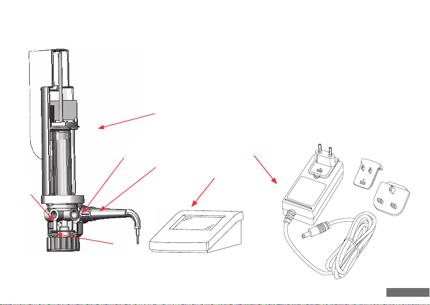
1. Ausstoßeinheit komplett
2. Rückführventil
3. Ansaugventil
4. Ausstoßventil
5. Basiseinheit
5
4
1
2
3
Das Netzteil kann in der jeweiligen landesspezifischen Ausführung im Lieferumfang abweichen.
The power supply unit may derivate from the specific national design in the scope of delivery.
6. Bedieneinheit
7. Netzteil
6
1. Ejection unit (complete)
2. Recirculation valve
3. Suction valve
4. Ejection valve
5. Basic unit
6. Control unit
7. Power supply unit
7
9
Page 10

3. Funktionsübersicht
3. Function overview
- Das Gerät ist ein motorisch betriebenes System zum
Titrieren von Flüssigkeiten. Das Grundgerät (Gewinde A 45)
und die Adapter-Varianten (siehe Zubehör) ermöglichen
den Einsatz von handelsüblichen Reagenzflaschen.
- Das System arbeitet nach dem Kolbenhubprinzip über
Kugelventile. Der Vorschub der Kolbeneinheit erfolgt
über einen zahnradgetriebenen DC-Motor mit lnkrementkennung. Die Ansteuerung erfolgt über eine Mikroprozessorsteuerung. Die Stromversorgung erfolgt über
ein Netzteil. Optional ist ein Akkubetrieb möglich.
Hinweis:
Das Geräteoberteil der Basiseinheit ist nicht gas- und
feuchtigkeitsdicht. Ein Betrieb in ätzenden Dämpfen ist
daher unzulässig.
- The unit is a motorised liquid titrating system. The
basic unit (A 45 thread) and adapter variants (see
accessories) facilitate the use of commercially available
reagent bottles.
- The system employs the piston stroke principle and
functions via ball valves. The piston unit is advanced
by a DC motor with gear drive and increments.
Actuation is realized with a microprocessor control.
Power is supplied by a power supply unit. The unit
can be optionally powered with a battery pack.
Note:
The upper part of the basic unit is not sealed against
gas and damp. It is therefore not permissible to operate
the unit in caustic fumes.
10
Page 11

3. Funktionsübersicht
3. Function overview
- Beim Hochziehen der Kolbeneinheit öffnet sich das
Ansaugventil. Aus einer Vorratsflasche wird durch den
Ansaugschlauch Flüssigkeit in den Zylinder gesaugt.
Das Ansaugventil schließt nach Beendigung des Ansaug-
vorganges.
- Beim Niederfahren der Kolbeneinheit öffnet sich das
Ausstoßventil und die sich im Zylinder befindliche
Flüssigkeit wird ausgestoßen.
- The suction valve is opened when the piston unit is
drawn upwards. Liquid is suctioned into the cylinder
from a storage bottle through the suction hose.
The suction valve closes when suctioning is completed.
- The ejection valve is opened when the piston unit is
lowered and the liquid in the cylinder is ejected.
11
Page 12

4. Einsatzverbote
4. Prohibited use
Das Gerät ist nicht zu verwenden bei:
- FIüssigkeiten, welche die Materialien Halar (ECTFE),
FEP, PTFE, Borosilikatglas 3.3 oder Hastelloy angreifen.
- Suspensionen (z. B. Aktivkohle-Suspension), da feste
Partikel die Ventile verstopfen können.
- Flusssäure, da sie Glas angreift.
- Ieicht entzündlichen Medien (Flammpunkt beachten).
- Einsatz in explosionsgefährdeter Umgebung.
The unit should not be used with the following:
- Liquids which attack the materials Halar (ECTFE),
FEP, PTFE, borosilicate glass 3.3 or Hastelloy.
- Suspensions (e.g. active carbon suspension), as solid
particles can block the valves.
- Hydrofluoric acid, as it attacks glass.
- Combustible media (note the flashpoint).
- Use in potentially-explosive environments.
12
Page 13

5. Einsatzbeschränkungen
5. Restrictions on use
- Der Arbeitstemperaturbereich für Gerät und FIüssigkeit
liegt zwischen 4 °C und 40 °C.
- Einsatz des Gerätes und laden des optionalen Akkus
nur in Bereichen, in denen gewährleistet ist, dass keine
gefährliche explosionsfähige Atmosphäre auftritt.
- Nicht im explosionsgefährdeten Bereich ablegen.
Achtung - wichtiger Hinweis!
Bei festsitzender Kolbeneinheit niemals Gewalt anwenden.
Sofort Vorgang beenden und Grundreinigung durchführen
(siehe Punkt 11).
- The working tempemture range for the unit and liquid
lies between 4 °C and 40 °C.
- The unit should only be used and optional batteries
loaded in areas where if can be assured that no
hazardous potentially explosive atmospheres occur.
- Do not deposit in potentially explosive areas.
Attention - important information!
Never use force if the piston unit has seized.
Terminate the process immediately and realize basic
cleaning (see point 11).
13
Page 14

6. Gerät vorbereiten
6. Preparing the unit
Achtung, vor Montagebeginn beachten!
- Alle Teile auf eventuelle Beschädigung überprüfen!
- Ein einwandfreier und sicherer Betrieb des Gerätes ist
nur bei Verwendung der beiliegenden, unbeschädigten
Original-Zubehörteile gewährleistet.
- Niemals fremde oder beschädigte Zubehörteile
verwenden.
Warning, please note before assembly!
- Check all parts for evidence of damage!
- Flawless and safe operation of the unit is only
assured if the undamaged original accessories
included in the delivery are used.
- Never use damaged accessories or accesories
gloves.
14
Page 15

6.1 Einsetzen des Lichtschutzfensters
6.1 Using the light protection window
Um lichtempfindliche Medien zu schützen, kann das beigelegte eingefärbte Lichtschutzfenster mit dem vorhandenen
klaren Sichtfenster ausgetauscht werden.
Zum Entfernen des klaren Sichtfensters muss es zunächst auf
einer Seite angehoben werden, damit es aus der Verankerung
rutscht, danach auf der gegenüberliegenden Seite.
Nun kann das eingefärbte Lichtschutzfenster (richtige Lage
beachten) entsprechend eingesetzt werden.
The existing clear inspection window can be replaced with
the coloured UV protection window to protect media which
are sensitive to light.
The clear inspection window should be raised initially
on one side for removal to ensure that it slides out of its
fixture, and then raised again on the other side.
The coloured UV protection window can now be suitably
fitted (note correct position).
15
Page 16
6.2 Befestigung Ansaugschlauch
6.2 Securing the suction tube
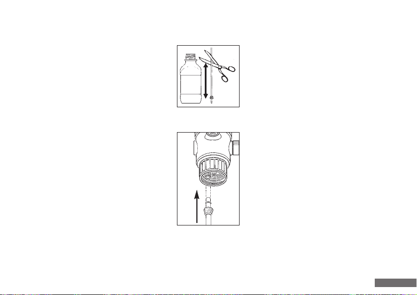
- Ansaugschlauch neben Vorratsflasche
stellen, dabei zeigt das Schlauchende
mit der Überwurfmutter zum Boden
der Flasche.
- Den Schlauch in Höhe der Unterkante
des Sicherungsrings der Vorratsflasche
schräg abschneiden.
- Ansaugschlauch bis zum Anschlag
aufstecken.
- Anschließend Überwurfmutter auf
Ansaugventil drehen.
- Hold the suction tube beside the storage bottle.
The hose end with the union nut should face
towards the base of the bottle.
- Cut the hose at a slant level to the lower
edge of the locking ring on the storage
bottle.
- Push the suction hose on up to the stop.
- Then tighten the union nut onto the
suction valve.
16
Page 17
6.3 Befestigung Rückführschlauch
6.3 Securing the recirculation hose
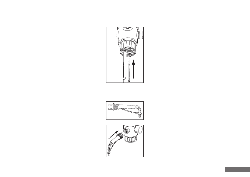
Rückführschlauch in die Rückführöffnung des
Ventilblocks fest einstecken.
6.4 Befestigung Ausstoßeinheit
- Ausstoßeinheit mit:
- Schlauchführung
- Überwurfmutter
- Ausstoßschlauch
- Verschlusskappe
- Ausstoßeinheit bis zum Anschlag aufstecken.
Insert the recirculation hose firmly into the
recirculation opening in the valve block.
6.4 Securing the ejection unit
- Ejection unit with:
- hose guide
- union nut
- ejection hose
- closure cap
- Push the ejection unit on up the stop.
17
Page 18
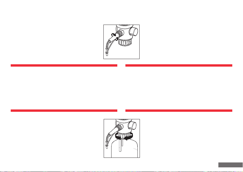
6.4 Befestigung Ausstoßeinheit
- Überwurfmutter gut festdrehen und auf
festen Sitz prüfen.
6.4 Securing the ejection unit
- Tighten the union nut firmly and ensure that
it is securely fitted.
Achtung!
- Festen Sitz der Ausstoßeinheit prüfen.
- Nur Original-Ausstoßeinheit verwenden
(siehe Punkt 19, Zubehör und Ersatzteile).
- Keine deformierte oder beschädigte Ausstoßeinheit
einsetzen.
6.5 Gerät auf Flasche schrauben
Gerät mit oder gegebenenfalls ohne Gewindeadapter auf Vorratsflasche schrauben.
Attention!
- Ensure that the ejection unit is securely fitted.
- Only use original ejection unit
(see point 19, Accessories and spare parts).
- Do not connect a deformed or damaged ejection unit.
6.5 Screwing the unit onto the bottle
Screw the unit onto the storage bottle
(use the threaded adapter where appropriate!)
18
Page 19

6.6 Ausstoßeinheit in gewünschte Position drehen
6.6 Turning the ejection unit to the correct position
Durch zwei im Gerät integrierte Drehachsen kann das Gerät
und die Ausstoßeinheit in nahezu beliebiger Richtung
zueinander ausgerichtet werden.
Warnhinweise!
- Sämtliche Sicherheitsbestimmungen, Einsatzverbote
und Einsatzbeschränkungen beachten.
- Schutzkleidung, Schutzbrille und Schutzhandschuhe
verwenden.
6.7 Gerät zum Flaschenetikett ausrichten
- Gerät in gewünschte Position zur Flaschenbeschriftung
drehen.
- Das Gerät darf nicht direkt am rechten Anschlag der
Drehachse positioniert sein (Demontageposition, siehe
Punkt 12.2).
The unit and ejection unit can be aligned in practically any
direction relative to each other, thanks to two rotation axes
integrated in the unit.
Warning!
- Observe all safety instructions, usage prohibitions
and restrictions on use.
- Wear protective clothing, safety glasses and
protective gloves.
6.7 Bottle label aligning unit
- Turning the unit into the desired position relative to the
bottle label.
- The unit should not be positioned directly at the
right-hand stop of the rotation axis (see point 12.2 for
dismantling position).
19
Page 20

6.8 Akku Einbau (optional)
6.8 Battery installation (optional)
Für den Einbau des Akkupacks muss die Bedieneinheit
geöffnet werden. Bevor mit dem Einbau begonnen werden
darf, müssen alle Kabel von der Bedieneinheit entfernt
werden. Danach sind die 4 Schrauben auf der Rückseite der
Bedieneinheit zu lösen (Kreuzschlitz PZ1).
Die Bedieneinheit ist dann wieder auf die Füße zu stellen.
Nach der Abnahme des Deckels muss die Elekronikeinheit
über den oberen Rand des Gehäuses weggekippt werden,
hierbei ist auf die Kabelführung zu achten. Der Akkupack
wird nun mit Hilfe der beiliegenden doppelseitigen Klebebänder in der Mitte des Gehäusebodens fixiert.
Hierbei muss beachtet werden, dass die Anschlusskabel
des Akkus in der rechten oberen Ecke sitzen.
Der Anschlussstecker des Akkus ist auf dem entsprechenden
Anschluss der Elektronikplatine einzustecken.
Danach kann die Elektronikplatine wieder auf ihren Sockel
gesetzt, der Deckel aufgesetzt und die Schrauben wieder
handfest angezogen werden. Auch hierbei ist auf die
Kabelführung zu achten.
The control unit should be opened to facilitate installation
of the battery pack. All cables should be removed from
the control unit prior to commencing battery installation.
All 4 screws at the rear of the control unit should then be
loosened (Phillips screw PZ1).
The control unit should then be rested on its feet again.
The electronic should be tilted away over the upper edge
of the housing after removing the cover. Attention should
be paid to the wiring during this. The battery pack is then
fixed in the centre of the housing floor with the assistance
of the double-sided adhesive tapes provided.
Ensure that the connection cables for the battery are in the
upper right-hand corner during this.
The battery connection plug should be connected to the
respective connection on the PCB.
The PCB can then be positioned on its base, the cover replaced and screws hand-tightened again. Attention should
once more be paid to the wiring during this.
20
Page 21

6.9 Akku laden (optional)
6.9 Battery charging (optional)
Grundsätzlich ist das Gerat über Netzbetrieb sofort einsatzbereit. Für den optionalen Akkubetrieb muss der Akku vor
der ersten Inbetriebnahme geladen werden:
Wenn das Netzteil angeschlossen ist, wird der Akku, unabhängig davon, ob das Gerät ein- oder ausgeschaltet ist,
geladen.
Der Ladevorgang wird über die Akkuanzeige im Display,
beziehungsweise bei ausgeschaltetem Gerät durch Blinken
einer roten LED am Displaymodul angezeigt. Ist der Akku
voll, wird der Ladevorgang automatisch beendet (der Akku
kann nicht überladen werden!) und es blinkt eine grüne
LED am Displaymodul. Das Gerät ist auch während des
Ladevorgangs betriebsbereit.
Sobald die Akkukapazität nicht mehr ausreicht um einen
ordnungsgemäßen Betrieb zu gewährleisten, erscheint
eine Warnmeldung im Display. Eine Weiterarbeit ist dann
erst nach dem Anschließen des Netzteils möglich.
The unit is, in principle, ready for immediate use when
connected to the mains power supply. However, the battery
should be charged prior to initial commissioning if operation
with the battery option is chosen.
The battery is charged when the power supply unit is
connected, regardless of whether the unit is activated or
deactivated.
Charging is indicated by the battery indicator on the display
and by the flashing red LED on the display module if the
unit is switched off. Charging is terminated automatically
when the battery is fully charged (battery overloading
is impossibIe!) and a green LED flashes on the display
module. The unit is also ready for operation during battery
charging.
A warning message appears on the display when the battery
capacity is no longer adequate to ensure correct operation.
Work may only be continued in this case after the power
supply unit is connected.
21
Page 22
6.9 Akku laden (optional)
6.9 Battery charging (optional)
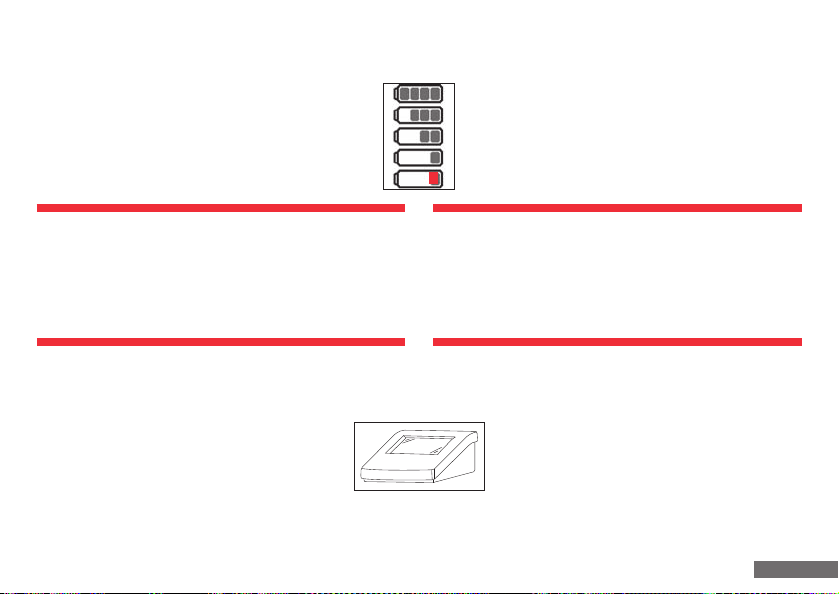
Akku 75 - 100 %
Akku 50 - 75 %
Akku 25 - 50 %
Akku 12 - 25 %
Akku < 12 %
Achtung:
Das Gerät darf nur mit dem Original-Netzteil betrieben
werden. Die Netzspannung muss mit der auf dem
Netzteil angegebenen Spannung übereinstimmen!
(Max. Abweichung ± 10%).
7. Arbeitsbeginn
Basisgerät und Bedieneinheit mit dem
beigelegten Kabel verbinden
(blauer 5-poliger Stecker und Buchse).
Stromversorgung durch anschließen des Netzteils (optional
Akku) sicherstellen. Das Gerät ist nun betriebsbereit.
Battery 75 - 100 %
Battery 50 - 75 %
Battery 25 - 50 %
Battery 12 - 25 %
Battery < 12 %
Warning:
The unit should only be operated with the original power
supply unit. The mains voltage must correspond to the
voltage specified on the power supply unit!
(Max. deviation ± 10%).
7. Start of work
Connect the basic unit and control unit with the
cable provided (blue 5-pole connector and socket).
Establish the power supply by connecting the
power supply unit (or, optionally, the battery
pack). The unit is now ready for operation.
22
Page 23
7.1 Symbolübersicht
7.1 Overview of symbols
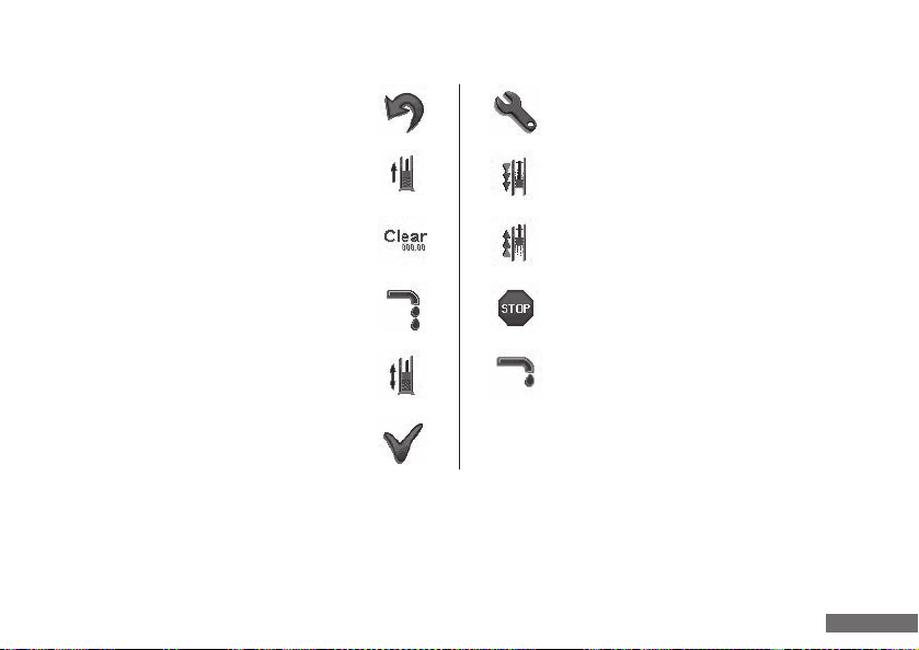
Abbrechen
Abort
Befüllen
Filling
Clear
Clear
Schnelltitration
Rapid titration
Entlüften
Venting
OK
OK
In bestimmten Arbeitszuständen, insbesondere wenn
gerade ein Vorgang (Titrieren, Entlüften usw.) abläuft,
können nicht alle Tasten bedient werden. Diese werden
dann vorübergehend inaktiv gesetzt. Inaktive Tasten werden
mit einem grauen Symbolrahmen dargestellt.
Menü
Menu
Ausstoßgeschwindigkeit
Ejection speed
Ansauggeschwindigkeit
Suctioning speed
STOP
STOP
Tropfentitration
Droplet titration
Not all buttons can be used when certain operating conditions
prevail, particularly if a process (titration, venting, etc.) is
currently active. These are then temporarily deacivated.
Inactive buttons are illustrated with a grey symbol margin.
23
Page 24
7.2 Gerät ein-/ausschalten
7.2 Activating/deactivating the unit
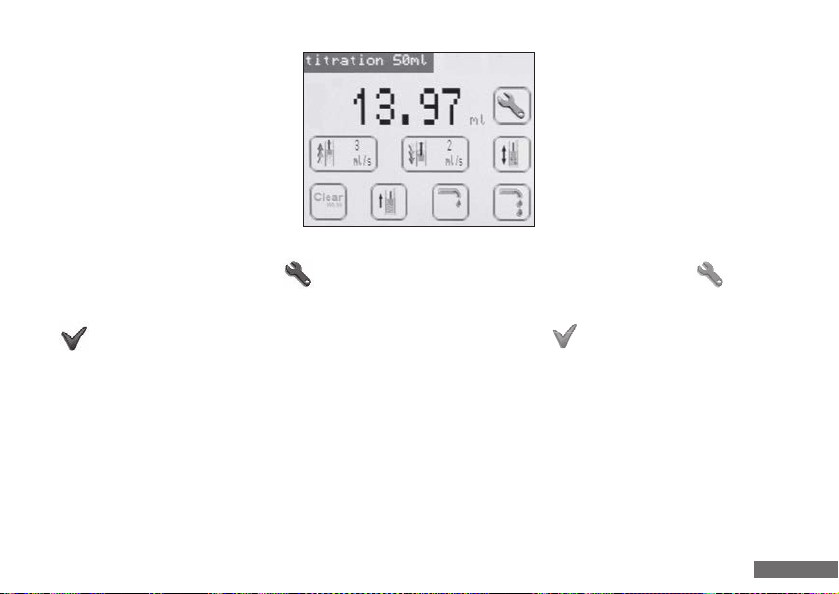
Durch ca. 2 s langes Drücken auf den
Touchscreen wird das Gerät in Betrieb
genommen. Es erscheint nun folgender
Bildschirm:
Um das Gerät auszuschalten, das Menü aufrufen, den
Menüpunkt „Off“ auswählen.
Mit bestätigen.
- Wird das Gerät nur über den optionalen Akku mit Strom
versorgt, schaltet es nach 5 Minuten ohne Bedienereingabe oder aktivem Vorgang automatisch aus.
- Es bleiben sowohl beim Ausschalten über die „Off“-Taste
als auch beim automatischen Ausschalten alle Benutzereinstellungen erhalten, so dass durch erneutes Drücken des
Touchscreens sofort weiter gearbeitet werden kann.
The unit is activated by pressing the
touch screen for approx. 2 s.
The following screen then appears:
To switch off the unit, activate the menue , and
select the “Off“ menu item.
Acknowledge with .
- If the unit is only supplied with power via the optional
battery, it deactivates automatically after 5 minutes in
the absence of entries by the user or if no process is
currently active.
- All user configurations are retained if the unit is
deactivated automatically or with the “Off“ button, so
that work can be continued immediately by pressing
the touch screen again.
24
Page 25

7.2 Gerät ein-/ausschalten
Achtung!
- Sicherheitsvorschriften einhalten
(siehe Punkt 1)!
- Einsatzverbote und Einsatzbeschränkungen beachten
(siehe Punkt 4 und 5).
- Gerät nur so bedienen, dass Ausstoßeinheit stets
vom Bediener und anderen Personen abgewandt ist.
Hierzu die Ausstoßeinheit mit Ventilblock wahlweise
nach rechts oder links vom Körper wegpositionieren.
7.2 Activating/deactivating the unit
Warning!
- Safety instructions must be observed
(see point 1)!
- Usage prohibitions and restrictions of use must be
observed (see point 4 and 5).
- The unit should only be utilised with the ejection
unit turned away from the user and other persons.
The ejection unit and valve block should be positioned
turned away to the left or right of the body for this
purpose.
25
Page 26
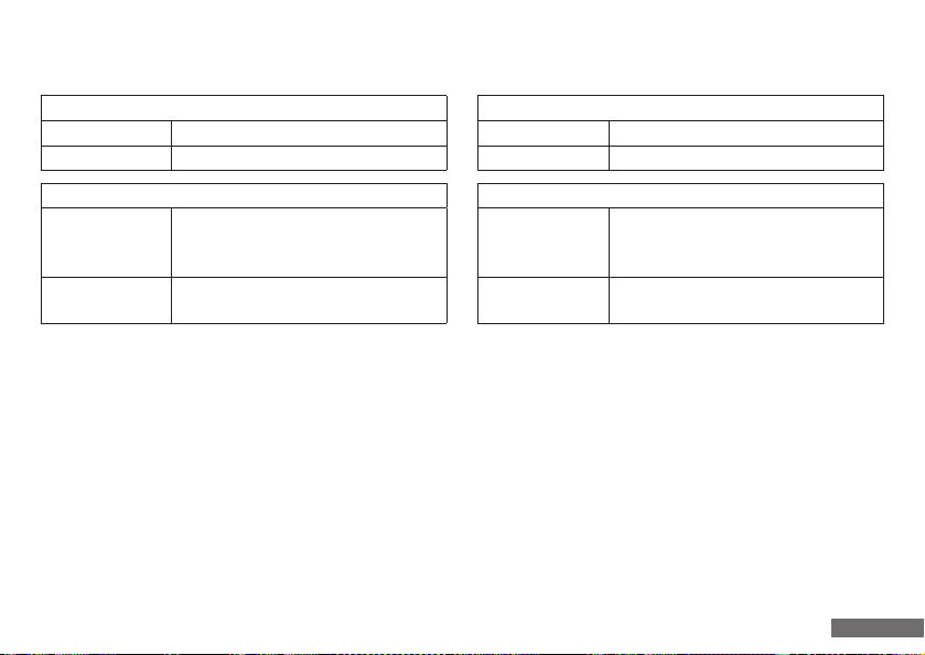
7.3 LED Status
7.3 LED status
Basiseinheit
LED blinkt grün Gerät betriebsbereit
LED blinkt rot Störung (siehe Punkt 16)
Bedieneinheit
Netzteil eingesteckt, bzw. Netzteil eingesteckt
LED blinkt grün
LED blinkt rot
und Akku vollständig geladen
(nur bei ausgeschaltetem Gerät)
Akku wird geladen
(nur bei ausgeschaltetem Gerät)
7.4 Wahl der Dezimalstellen (10 ml)
Als Ergänzung zu den Gerätevarianten 50 und 20 ml können durch die 10 ml Variante kleinere Geschwindigkeiten
und höhere Genauigkeiten realisiert werden.
Basic unit
LED flashes green Unit ready for operation
LED flashes red Error (see point 16)
Control unit
Power supply unit plugged in or power supply
LED flashes green
LED flashes red
unit plugged in and battery fully charged
(only when the unit is deactivated)
Battery charging
(only when the unit is deactivated)
7.4 Modification of decimal places (10 ml)
In addition to the 50 ml and 20 ml unit the 10 ml unit allows slower velocities and greater accuracy to be achieved.
26
Page 27
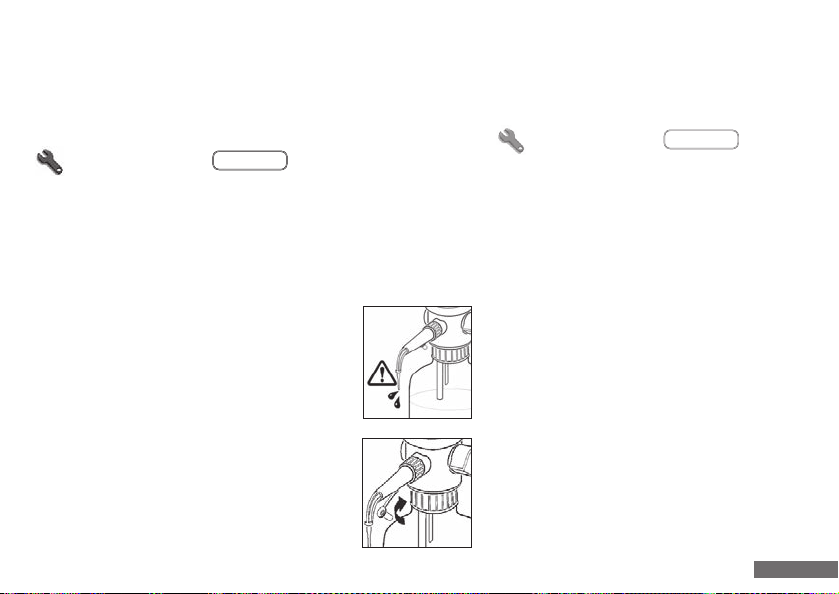
.00 / .000
7.4.1 Dezimalstellen der Volumenanzeige ändern
7.4.1 Modify displayed decimal places
Beim 10 ml Gerät kann die Anzeige des Volumens mit
wahlweise 2 oder 3 Dezimalstellen erfolgen.
Um die Anzahl der Dezimalstellen umzustellen, das Menü
aufrufen und die Taste betätigen.
.00 / .000
Es wird danach direkt der Hauptbildschirm mit der geänderten Einstellung angezeigt. Beim Wechsel von 3 zu 2
Dezimalstellen wird die 3. Stelle abgeschnitten.
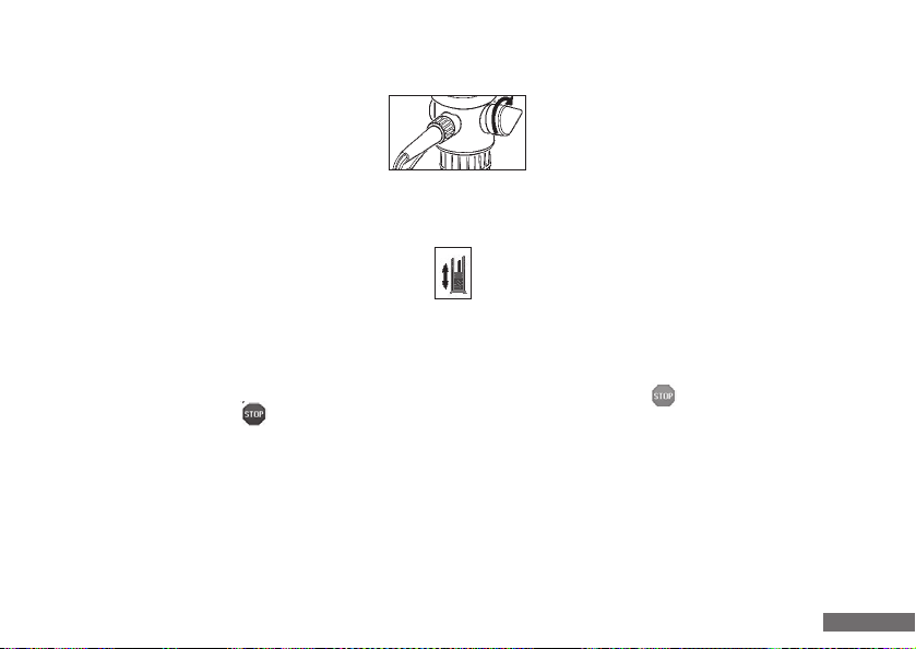
7.5 Verschlussklappe abnehmen
- Auffanggefäß unter Ausstoßeinheit stellen.
- Verschlusskappe, wie in der Abbildung gezeigt,
abziehen. Achtung: Dabei kann Reagenz
heraustropfen!
- Verschlusskappe entsprechend der
Abbildung nach hinten schieben. Während
des Arbeitens kann die Verschlusskappe in
der Aufbewahrungsposition verbleiben.
The volume for the 10 ml unit can be displayed to either 2
or 3 decimal places. To switch from one to the other call up
the menu and press the button .
The main display with the changed setting will then appear. When switching from 3 decimal places to 2 places the
third place will be cut off.
7.5 Closure cap removal
- Position a collecting vessel under the ejection unit.
- Pull of the closure cap as shown in the illustra-
tion. Warning: reagent can drop out during
this operation!
- Push the closure cap to the rear as shown in
the illustration. The closure cap can remain
in the retention position while work is being
realized.
27
Page 28
7.6 Entlüften des Gerätes
7.6 Venting the unit
Bei sichtbarer Luftblasenbildung im Zylinderraum z. B. nach Aufschrauben auf ein neues
Vorratsgefäß und dann erfolgtem Befüllen,
ist der Rückführhebel auf „Rückführen“
(Spitze des Rückführhebels zeigt nach hinten)
zu stellen.
Die Automatische Entlüftung des Gerätes erfolgt über das
Symbol „Entlüften“ im Hauptfenster.
Nach dem Drücken auf das Symbol wird 1 ml angesaugt
und der Kolben entleert. Danach wird 40% des Nennvolumens
angesaugt und wieder abgegeben. Beim Entlüften wird das
Symbol „Entlüften“ zu einem „STOP“-Symbol. Durch das
Drücken des „STOP“-Symbols kann der Entlüftungsvorgang abgebrochen werden.
Wurde das Gerät nach der letzten Benutzung ordnungsgemäß ausgeschaltet und die Bedieneinheit nicht von der
Basiseinheit getrennt, ist ein Entlüften nach dem Einschalten
nicht zwangsläufig nötig, aber empfehlenswert.
The recirculation lever should be positioned at
recirculation (the tip of the recirculation lever
points backwards) if air bubbles visibly form in
the cylinder chamber (e. g. after screwing onto
a new storage vessel and subsequent filling).
The unit is then automatically vented using the “Venting“
symbol in the main window.
1 ml is suctioned and the cylinder drained when the
symbol is pressed. 40% of the nominal volume is then
suctioned and dispensed again. Then “Venting“ symbol
is converted into a “STOP“ symbol during venting.
The venting process can be interrupted by pressing the
“STOP“ symbol.
Venting is not compulsory if the unit was correctly deactiva ted after its last use and the control unit not detached
from the basic unit. However, venting is recommended in
this case.
28
Page 29

7.6 Entlüften des Gerätes
In machen Fällen ist es zwingend, beim Einschalten des
Systems zuerst eine Entlüftung durchzuführen. Dies zeigt
sich dadurch, dass dann nur die „Entlüften“- und die
„Menü“ Taste aktiv sind.
7.6 Venting the unit
It is imperative in some cases that venting will be realized
first when activating the system. This is indicated in that
only the “Venting“ and “Menu“ buttons are then
active.
8. Titrieren
Beim Titrationsvorgang wird das Volumen, welches durch
die verschiedenen Funktionen abgegeben wird, laufend
addiert. Beim Erreichen des Titrationsendpunktes kann
dieser Wert im Display abgelesen werden.
8. Titration
During titration, the volume dispensed through the
different functions is continually added. This value can
be viewed on the display when the titration end point is
reached.
29
Page 30
8.1 Befüllen
8.1 Filling
- Bei einem Druck auf das Symbol
„Befüllen“ im Hauptfenster wird
der Glaszylinder mit dem Nennvolumen
von 10, bzw. 20 oder 50 ml gefüllt.
- Es besteht auch die Möglichkeit, ein
beliebiges Volumen in den Zylinder zu
füllen. Dafür wird vor dem Füllen im
Hauptfenster das anzusaugende
Volumen eingestellt.
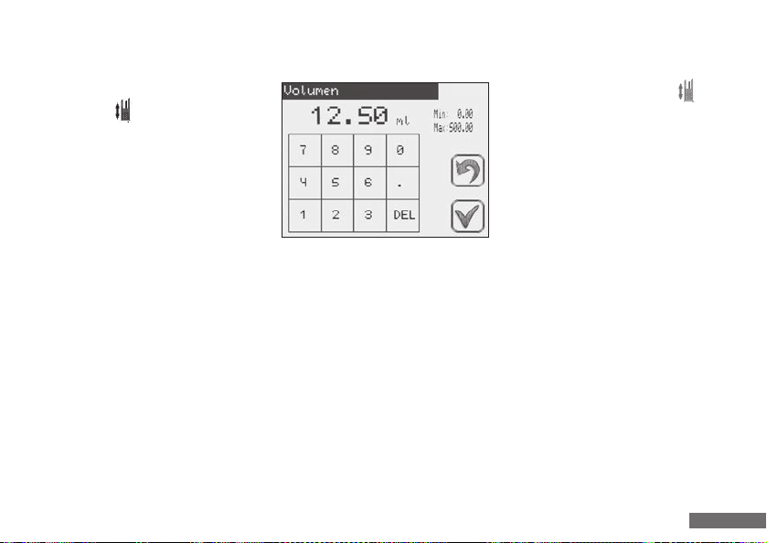
Alle Menüs sind nach dem selben Schema aufgebaut:
- Beim Drücken auf die Volumenanzeige öffnet sich ein
Eingabefeld. Der momentane Wert befindet sich un-
mittelbar darunter. Daneben stehen Vorgaben über den
Minimal- und Maximalwert, welche nicht über- bzw.
unterschritten werden dürfen.
- Die Eingabe des neuen Wertes erfolgt über die Ziffernfolge, falsche Eingaben können über das Feld „DEL“
korri giert werden.
- Pressing the “Filling“ symbol in
the main window fills the glass
cylinder with the nominal volume of
10, 20, or 50 ml.
- It is possible to fill the cylinder with a
randomly-selected volume. The volume
to be suctioned is configured in the
main window prior to filling for the
purpose.
All menus are laid out with the same schematic:
- An input field opens when the volume indication is
pressed. The current value is shown immediately
beneath. The minimum and maximum value are dis-
played adjacent to this, and these values should not be
exeeded or undershot.
- Inputting of the new value is realized via the numerical
sequences, and incorrect entries can be corrected with
the “DEL“ field.
30
Page 31
8.1 Befüllen
8.1 Filling
- Beim Drücken auf den Symbol „OK“ wird der neue
Wert übernommen, sofern dieser gültig ist. Im Falle
eines ungültigen Wertes bitte die Min.- und Max.-Werte
berücksichtigen.
- Beim Drücken auf das Symbol „Abbrechen“ wird
der neue Wert verworfen und das Hauptfenster öffnet
sich.
Wurde die Eingabe mit „OK“ bestätigt erscheint das
nun eingestellte Volumen mit einem „* “ als Indikator
rechts neben der Anzeige. Dieser Indikator zeigt an, dass
aktuell nicht das Titriervolumen sondern ein Vorwahlvolumen im Display steht. Über das Symbol „Befüllen“
im Hauptfenster wird der Zylinder mit den Vorwahlvolumen
befüllt.
- The new value is imported by pressing the “OK“
symbol, provided it is valid. Please note the min. and
max. values in the case of an invalid value.
- The new value is rejected by pressing the “Abort“
symbol and the main window opens.
If the entry is acknowledged with “OK“ , the volume
now configured is displayed with an “* “ as indicator to
the right of the display. This indicator illustrates that not
the titration volume, but rather the preselected volume is
currently shown on the display. The cylinder is filled with
the preselected volume using the “Filling“ symbol in
the main window.
31
Page 32
8.2 Einstellen der Ansaug- bzw. Ausstoßgeschwindigkeit
8.2 Configuring the suctioning and ejection speed
Es ist möglich, die Ansaug- und Ausstoßgeschwindigkeit
unabhängig voneinander einzustellen. Die aktuellen Werte
in (ml/s) werden im Hauptbildschirm rechts neben den
entsprechenden Symbolen dargestellt. Die eingestellten
Geschwindigkeiten können je nach Umgebungs- und
Einsatzbedingungen leicht variieren.
- Beim Drücken auf das Symbol für den Ansaug- bzw.
für die Ausstoßgeschwindigkeit öffnet sich ein
Eingabefeld, in welchem oben der Parameter angezeigt
wird. Der momentane Wert befindet sich unmittelbar
darunter. Daneben stehen Vorgaben über den Minimalund Maximalwerte, welche nicht über- bzw. unterschritten werden dürfen.
- Die Eingabe des neuen Wertes erfolgt über die Ziffern-
folge, falsche Eingaben können über das Feld „DEL“
korrigiert werden.
- Beim Drücken auf „OK“ wird der neue Wert übernommen, sofern dieser gültig ist. Im Falle eines ungültigen
Wertes bitte die Min.- und Max.-Werte berücksichtigen.
- Beim Drücken auf „Abbrechen“ wird der neue Wert
verworfen und das Hauptfenster öffnet sich.
It is possible to configure the suctioning and ejection
speed independently of each other. The current values are
illustrated in (ml/s) on the right of the main srceen beside
the respective symbols. The speeds configured can vary
slightly depending on the ambient and operating conditions.
- An input field is opened in which the parameter is
shown at the top when the symbol for the suctioning
speed and ejection speed is pressed.
The current value is shown immediately beneath. De-
tails of the minimum and maximum value are displayed
adjacent to this, and these values should not be exceeded or undershot.
- Inputting of the new value is realized via the numercial
sequencs, and incorrect entries can be corrected with
the “DEL“ field.
- The new value is imported by pressing the “OK“
symbole, provided it is valid. Please note the min. and
max. values in the case of an invalid value.
- The new value is rejected by pressing the “Abort“
symbol and the main window opens.
32
Page 33
8.3 Schnelltitration
8.3 Rapid titration
- Schnelltitration ohne Volumenvorwahl: Durch Drücken
des Symbols wird Titriervolumen abgegeben. Der
aktuell ausgegebene Volumenwert wird in der Volumenzeile angezeigt. Nach dem Loslassen der Taste wird der
Vorgang sofort gestopppt.
- Schnelltitration mit Volumenvorwahl: Ein zuvor über die
Ziffernfolge eingegebenes Volumen wird nach dem
Drücken der Taste Schnelltitration abgegeben.
Das Volumen wird hier wie im Punkt 8.1 beschrieben
eingestellt.
- Wurde die Eingabe mit „OK“ bestätigt, erscheint
das nun eingesellte Volumen mit einem „* “ als
Indikator rechts neben der Anzeige. Dieser Indikator
zeigt an, dass aktuell nicht das Titriervolumen sondern
ein Vorwahlvolumen im Display steht.
- Rapid titration without voIume preselection:
The titration voIume is dispensed by pressing the
symbol. The voIume value currently dispensed is
indicated in the volume line. The process is stopped
immediately if the button is released.
- Rapid titration with volume preselection: A volume
previously entered via the numerical sequence is
dispensed after the rapid titration button is pressed.
The voIume is configured here as described in point 8.1.
- If the entry is acknowledged with “OK“ , the volume
now configured is displayed with an “* “ as indicator to
the right of the display. This indicator illustrates that not
the titration volume, but rather the preselectet volume
is currently shown on the display.
33
Page 34
8.3 Schnelltitration
8.3 Rapid titration
Hinweis
System bringt automatisch die letzten 10% des Vorwahlvolumens tropfenweise aus. Nach Beenden wird
der abgegebene Wert in der Volumenzeile angezeigt.
Wichtiger Anwendungsvorteil:
Über die STOP-Taste kann während des Titriervor
gangs mit Volumenvorwahl die laufende Volumenabgabe sofort gestoppt werden. In der Volumenzeile
erscheint der abgegebene Volumenwert. Selbstver
ständlich ist ein Weiterarbeiten mit der Taste „Schnelltitration“ oder „Tropfentitration“ jederzeit
möglich.
Note
The system automatically generates the last 10% of the
preselected volume in droplets. The value dispensed is
displayed in the volume line on completion.
Important user advantage:
-
The STOP button can be used during titration with a
preselected voIume to stop the current volume dispensing
immediately. The volume value dispensed is shown in
the volume line. Further working is, of course, possible
with the “Rapid titration“ or “Droplet titration“
button at any time.
34
Page 35
8.4 Tropfentitration
8.4 Droplet titration
Bei Drücken auf das Symbol „Tropfentitration“ im
Hauptfenster wird tropfenweise Volumen abgegeben. Bei
längerem Halten der Taste wird die Tropfenabgabe beschleunigt. In der Volumenanzeige kann ständig die schon
angegebene Titriermenge abgelesen werden. Die kleinste
angezeigte Titriermenge beträgt 0,01 ml. Nach dem Loslassen der Taste wird der Vorgang sofort gestoppt.
Hinweis
Es ist sinnvoll, vor Erreichen des Farbumschlagens auf
die Tropfentitration zu wechseln, um kein
„Übertitrieren“ hervorzurufen.
Pressing the “Droplet titration“ symbol in the main
window dispenses the volume in droplets. Droplet dispensing is accelerated if the button is held for a longer
period. The titration volume already dispensed can be read
continually on the volume display. The smallest titration
volume indicated is 0.01 ml. The process is stopped immediately if the button is released.
Note
It is sensible to change to droplet titration before
the colour change is reached to avoid any excessive
titration.
35
Page 36
8.4 Tropfentitration
stellt sich die Anzeige
Hinweis
Wenn die noch im Glaszylinder befindliche Flüssigkeit
nicht für das eingegebene Volumen ausreicht, wird der
Zylinder automatisch wieder gefüllt. Mittels der vorhan denen Additionsfunktion wird immer das schon ausge gebene Volumen weiter aufaddiert.
8.4 Droplet titration
Note
If the liquid still contained in the glass cylinder is not
adequate for the configured volume, the cylinder
is automatically refilled. The available addition function
continually adds the volume already dispensed further.
8.5 Clear
Nach dem Drücken auf „CLEAR“ stellt sich die Anzeige
für das abgegebene Volumen in Ausgangsstellung (0,000 ml)
zurück. Somit kann ein neuer Titrationsvorgang gestartet
werden, ohne dass der Zylinder vorher entleert oder frisch
befüllt werden muss.
8.5 Clear
After pressing “CLEAR“ , the display for the volume
dispensed is reset to the start setting (0.000 ml). A new
titration procedure can thus be started without previously
emptying or refilling the cylinder anew.
36
Page 37
9. Sonderfunktionen
9. Special functions
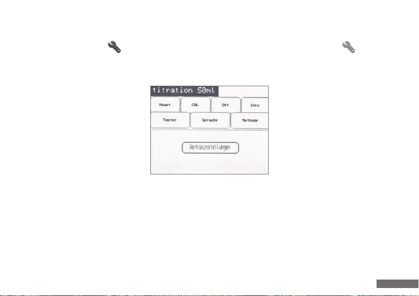
Aufzurufen über die „Menü“ Taste.
9.1 Hauptbildschirm
Über die Taste „Werkeinstellungen“ wird
das Gerät in den Werkszustand gesetzt.
Alle benutzerspezifischen Einstellungen
werden gelöscht. Das Rücksetzen kann in
der darauf folgenden Meldung bestätigt
oder abgebrochen werden.
Über den Menüpunkt „Haupt“ kommt
man zurück zum Hauptbildschirm.
These can be activated with the “Menu“ button.
9.1 Main screen
The unit is set to default mode by
pressing the “Default settings“ button.
All user-specified settings are deleted.
Resetting can be acknowledged or
interrupted in the subsequent message.
You can return to the main screen via
the “Main“ menu item.
37
Page 38
9.2 Sprachwahl
9.2 Language selection
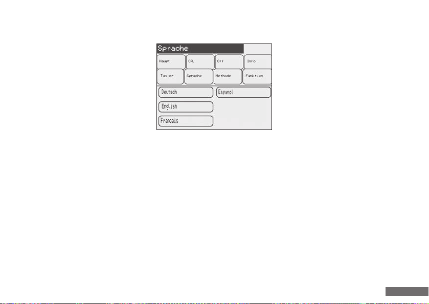
Der Anwender hat die Möglichkeit, zwischen
vier Display-Sprachen zu wählen:
- Deutsch
- Englisch
- Französisch
- Spanisch
Die Einstellung der Displaysprache erfolgt
im Untermenü „Sprache“.
Nach dem Drücken auf eines der Sprachfelder übernimmt
das Gerät die neue Sprache.
9.3 Quick-Cal
Das Gerät ist werkseitig für eine Bezugstemperatur von
20°C unter Berücksichtigung des kubischen Wärmeausdehnungskoeffizienten für Borosilikatglas (DIN ISO 4787)
auf Ablauf justiert (EX 20°C). Für die Justierung wird Wasser
der „Qualität 3“ nach DIN ISO 3696 verwendet.
The user can choose from four different
display languages:
- German
- English
- French
- Spanish
Configuration of the display language is
realized in the “Language“ submenu.
The units imports the new language after one of the
language fields is pressed.
9.3 Quick-Cal
The unit is configured by the manufacturer for a reference
temperature of 20°C, taking the cubic thermal expansion
coefficient for borosilicate glass (DIN ISO 4787) into
consideration (EX 20°C). Quality 3 water is used for this
adjustment, conforming to DIN ISO 3696.
38
Page 39
9.3 Quick-Cal
9.3 Quick-Cal
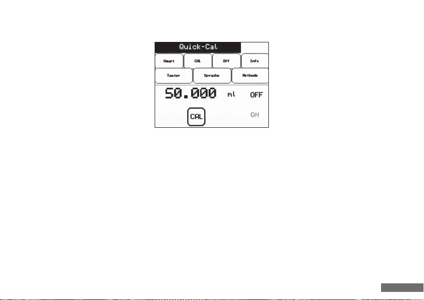
Die Kundenkalibrierung erlaubt dem Anwender, selbst sein Gerät auf jeden speziellen
Anwendungsfall exakt zu kalibrieren. Hierzu
werden 10 ml, 20 ml bzw. 50 ml (je nach
Gerät) des Mediums titriert, anschließend
auf einer ausreichend genauen Waage
verwogen und unter Berücksichtigung der
Dichte das tatsächliche Volumen errechnet.
Im Untermenü „CAL“ kann das tatsächliche
Volumen nun eingegeben werden. Hierbei ist zu beachten,
dass der Kundenkalibrierwert höchstens 10% vom Nennvolumen abweichen darf (bei zu hoher Abweichung erfolgt
eine Fehlermeldung). Nach erfolgreicher Aktivierung des
Kundenkalibrierwertes durch Drücken der Taste „CAL“ wechselt
die rechte Anzeige auf „ON“ und auch im Hauptfenster erscheint neben dem Volumen der Hinweis „CAL“. Das Gerät
korrigiert nun automatisch jedes zu dosierende Volumen
anhand der vorgenommenen Kalibrierung. Durch erneutes
Drücken der „CAL“-Taste kann der Kundenkalibrierwert auch
wieder deaktiviert werden, das Gerät arbeitet nun wieder
mit der Werkseinstellung. Der einmal eingegebene Kalibrierwert bleibt auch nach dem Ausschalten des Gerätes erhalten
und kann jederzeit aktiviert werden.
Customer calibration enables the user to
calibrate his unit himself to exactly suit
a special application case. 10 ml, 20 ml
or 50 ml (depending on the unit) of the
medium is dispensed for this purpose and
then weighed on an adequately-accurate
scale, with actual volume being calculated
taking the density into consideration. The
actual volume can now be entered in the
“CAL“ submenu. It is important to note here that the value
calibrated by the costumer should not deviate more than
10% from the nominal value (an error message is generated
if the deviation is too high). After successful activation of the
value calibrated by the costumer by pressing the “CAL“ button, the right-hand display changes to “ON“, and the “CAL“
indication also appears in the main window adjacent to the
volume. The unit now automatically corrects each volume
to be dispensed on the basis of the calibration realized. The
value calibrated by the customer can also be deactivated
again pressing the “CAL“ button again, and the unit now
continues working with the default setting. The calibration
value entered once is retained after the unit is switched off
and can be activated or deactivated at any time.
39
Page 40
9.4 PIN Schutzfunktion
Administrator PIN
9.4 PIN Protection
Alle Geräte sind mit einer Funktion zur Zugangsbeschränkung
ausgestattet. Über die Abfrage einer PIN beim Einschalten
des Gerätes kann wahlweise das komplette Gerät oder nur
bestimmte Einstellungen vor einer unberechtigten Bedienung
geschützt werden. Im Auslieferungszustand ist diese
Funktion deaktiviert.
9.4.1 PIN Schutz aktivieren
Um den PIN Schutz zu aktivieren, das Menü aufrufen
und die Taste „Administrator PIN“ aufrufen.
Administrator PIN
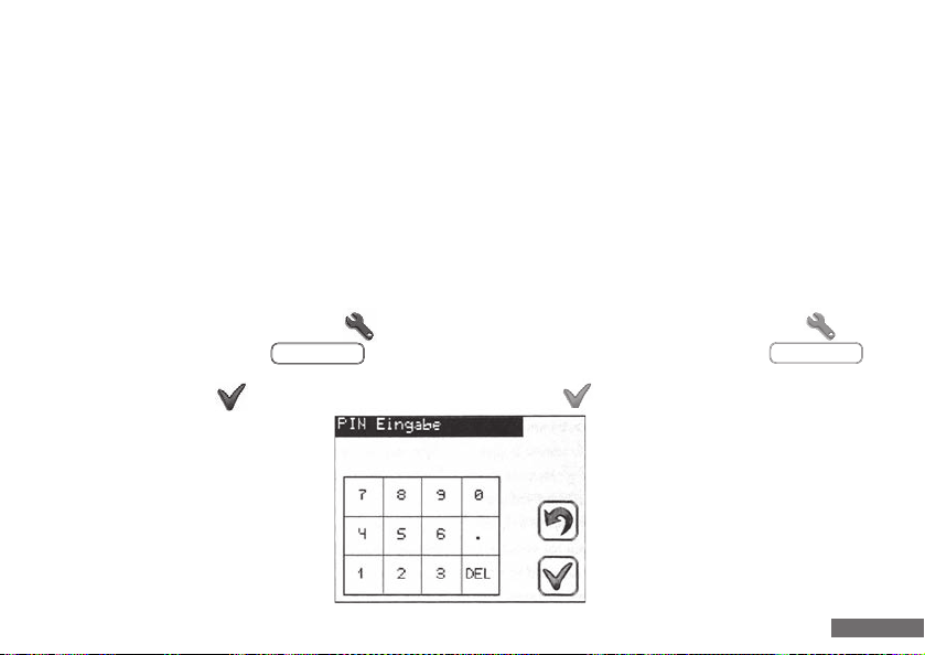
Im erscheinenden Menü kann nur eine vierstellige PIN
eingegeben und mit „OK“ bestätigt werden.
Beim nächsten Einschalten des Gerätes
erscheint nun derselbe Bildschirm. Wenn
die PIN korrekt eingegeben und mit OK
bestätigt wird, kann das Gerät wieder in
vollem Funktionsumfang genutzt werden.
Ohne die Eingabe der korrekten PIN kann
das Gerät nicht mehr genutzt werden.
All units are provided with a function to restrict user access.
If entry of a PIN is required after turning the unit on then
this PIN can either prevent the entire unit from being used,
or prevent settings from being changed by unauthorized
persons. This function is deactivated in the factory setting.
9.4.1 Activate PIN protection
To activate the PIN protection, select the menu and
then press the button “Administrator PIN”
A four-digit PIN can now be entered and confirmed by
pressing the button.
The next time the unit is switched
on the same display will appear. If the PIN is
entered correctly and confirmed by pressing
the tick button then the unit can be used
and all functions will be available. If the
correct PIN is not entered then it will not be
possible to operate the unit.
40
Page 41

9.4.2 PIN Schutz deaktivieren
Benutzer PIN
9.4.2 Deactivation of the PIN
Um einen bereits eingerichteten PIN Schutz zu deaktivieren,
die Taste Administrator PIN aufrufen. Im erscheinenden
Menü muss als Zifferncode viermal Null „0000“ eingegeben
und mit „OK“ bestätigt werden. Die Funktion ist dadurch
wieder komplett deaktiviert.
9.4.3 Eingeschränkte Benutzer PIN aktivieren
Sobald eine Administrator PIN vergeben wurde, kann zusätzlich noch eine Benutzer-PIN über die Taste
vergeben werden. Jeder, der sich beim Einschalten des
Gerätes über diese PIN anmeldet, hat nur einen eingeschränkten Zugriff auf das Gerät.
Benutzer PIN
If the unit protected through a PIN then this may be
deactivated using the Administrator PIN button. The code
“0000“ is then entered and confirmed by pressing the“OK”
button. This fully deactivates the PIN protection.
9.4.3 Activation of restricted user PIN
Once an Administrator PIN has been assigned an User PIN
can be additionally assigned through the button
Anyone who enters this PIN when using the unit will only be
able to access limited functions.
41
Page 42

9.4.3 Eingeschränkte Benutzer PIN aktivieren
9.4.3 Activation of restricted user PIN
Beim Titrierer können nur noch diese Funktionen bedient
werden:
- Schnelltitration
- Tropfentitration
- Clear
- Befüllen
- Volumeneinstellung
- Entlüften
- Menü à Gerät ausschalten
- Menü à Info
Wurde als Administrator PIN und als Benutzer PIN dieselbe
vergeben, reagiert das Gerät, als ob keine Benutzer PIN
vergeben wurde.
Only the following functions can be accessed for the
titration unit:
- Rapid titration
- Dropwise titration
- Clear
- Fill
- Adjust volume
- Venting
- Menu à Switch off
- Menu à Info
If the Administrator PIN and User PIN are the same then
the unit will react as if no User PIN has been assigned.
42
Page 43

9.4.4 Eingeschränkten Benutzermodus deaktivieren
9.4.4 Deactivation of restricted user mode
Um eine bereits eingerichtete Benutzer PIN zu deaktivieren,
die Taste Benutzer PIN aufrufen. Im erscheinenden Menü
muss als Zifferncode viermal Null „0000“ eingegeben und
mit „OK“ bestätigt werden. Die Funktion ist dadurch wieder
komplett deaktiviert. Wird wie unter Punkt 9.4.2 beschrieben die Administrator PIN gelöscht, wird auch automatisch
die Benutzer PIN mitgelöscht.
9.4.5 PIN vergessen
Wenn die Benutzer PIN vergessen wurde, kann man sich
beim Einschalten über die Administrator PIN anmelden und
dann über die Taste Benutzer PIN eine neue PIN festlegen.
Wurde die Administrator PIN vergessen, kann die in den
Gehäuseboden der Bedieneinheit eingeprägt Seriennummer
an Hirschmann Laborgeräte z. B.: über [email protected]
mitgeteilt werden. Eine neue PIN zur Freischaltung wird
Ihnen dann mitgeteilt.
To deactivate an User PIN already assigned the User PIN
button is pressed. It is then necessary to enter the code
„0000“ in the display and confirm this. This will fully
deactivate the restriction. If the administrator PIN is deactivated as described at point 9.4.2 above then the User PIN
will be automatically removed as well!
9.4.5 If the PIN is forgotten
If the User PIN has been forgotten then the user can log in
using the Administrator PIN and a new PIN can be entered
using the User PIN Button.
If the Administrator PIN has been forgotten then it is necessary to send the serial number of the dispenser stamped on
its base to Hirschmann Laborgeräte, for instance by emailing
it to [email protected]. A new PIN will then be sent
to you.
43
Page 44

9.5 Methode speichern
9.5 Method saving
Es ist möglich, im Gerät alle Einstellungen über Volumen
(bzw. Teilvolumen), aktueller Kundenkalibrierwert, aktiver
oder inaktiver Kundenkalibrierwert, Ansaug- und Ausstoßgeschwindigkeit als eine Methode zu speichern. Hierfür
stehen 9 Speicherplätze zur Verfügung.
Um eine Methode abzuspeichern, im Untermenü „Methode“
auf „Methode speichern“ drücken. Es erscheint ein Ziffernfeld, in welchem man einen Speicherplatz (1-9) auswählen
kann, in dem die Methode gespeichert werden soll. Bereits
belegte Speicherplätze werden durch rote Ziffern dargestellt,
können aber trotzdem überschrieben werden. Der ausgewählte
Speicherplatz erscheint über dem Ziffernfeld. Nach Drücken
von „OK“ ist die Methode unter dem gewählten Platz
gespeichert. Im Hauptfenster erscheint nun entsprechend
der abgespeicherten Methode der Hinweis M1-9 links
neben der Volumenanzeige.
It is possible to save all settings relating to volumes (or
partial volumes), current customer value calibration, active
or inactive customer value calibration, suctioning and
ejection speed as a method. Nine memory locations are
available for this purpose.
Press “Save method” in the “Method” submenu to save a
method. A numerical field appears in which you can select
a memory location (1-9) in which the method should be
saved. Memory locations which are already occupied are
indicated with red numbers, but these can be written over.
The memory location selected appears above the numerical
field. After pressing “OK” the method is saved to the
selected location. The indication M1-9 (depending on the
saved method) now appears in the main window to the
left of the volume indication.
44
Page 45
9.6 Methode abrufen
9.6 Activating the method
Um eine gespeicherte Methode abzurufen, im Untermenü
„Methode“ auf „Methode abrufen“ drücken. Es erscheint
ein Ziffernfeld, in welchem die abzurufende Methode ausgewählt werden kann. Nicht belegte Speicherplätze sind
grau unterlegt und können nicht ausgewählt werden.
Mit einem Druck auf „OK“ wird die neue Methode
übernommen und man gelangt zum Hauptfenster. Im
Hauptfenster erscheint nun entsprechend der aufgerufenen
Methode der Hinweis M1-9 links neben der Volumenanzeige.
Hinweis
Sobald nach dem Speichern oder Aufrufen einer Methode
ein Wert verändert wurde, erlischt die Anzeige M1-9
wieder im Display, da nun nicht mehr noch der Methode
gearbeitet wird. Die Methoden für eine 10, 20 und 50 ml
Basiseinheit werden in einem separaten Speicherplatz
in der Bedieneinheit abgespeichert. Somit hat jede
Gerätevariante seine eigenen 9 Speicherplätze. Eine z. B.
mit einem 20 ml Gerät gespeicherte Methode lässt sich
nicht mit einem 50 ml Gerät aufrufen.
In order to activate a saved method, press “Activate
method” in the “Method” submenu. A numerical field
appears in which the method to be activated can be
selected. Unoccupied memory locations have a grey
background and cannot be selected. Pressing “OK”
imports the new method and you change to the main
window. The indication M1-9 now appears in the main
window to the left of the volume indication.
Note
The M1-9 indication disappears on the display again
as soon as a value has been changed after saving or
activation of a method, as work is no longer realized
according to this method. The same applies if work is
realized alternately with a 10, 20 and 50 ml basic unit
using the same control unit. This means that each unit
type has its own 9 memory locations. For example, a
method saved with a 20 ml unit cannot be activated
with a 50 ml unit.
45
Page 46

9.7 Taster
9.7 Switches
Durch den Anschluss von Zusatzgeräten können bestimmte
Tasten des Hauptbildschirms von extern angesteuert werden.
Folgende Geräte stehen hierbei z. Zt. zur Verfügung:
- Fußtaster
- Handtaster
- Zwei-Tasten-Maus
- Steuerkabel
Das Zusatzgerät wird an die Bedieneinheit des Geräts
angeschlossen. Pro Bedieneinheit kann nur ein Zusatzgerät
angeschlossen werden. Die Fuß- und Handtaster haben
jeweils eine Tastenfunktion, die Maus und das Steuerkabel
können mit 2 Tastenfunktionen belegt werden.
Zur Einrichtung dieser Funktion muss das Zusatzgerät zunächst
an die dafür vorgesehene schwarze Schnittstelle an der
Bedieneinheit angeschlossen werden. Dann im Untermenü
„Taster“ auf die Schaltfläche „Taster 1“ bzw. „Taster 2“
drücken. Innerhalb dieser Schaltflächen ist aufgelistet,
welches Zusatzgerät unter „Taster 1“ bzw. „Taster 2“ eingerichtet werden kann. Es öffnet sich ein weiteres Untermenü, in dem durch Drücken auf eines der Symbole die
Funktion dem Taster zugeordnet werden kann.
The connection of additional devices enables external actuation
of certain button on the main screen. The following devices
are currently available for this purpose:
- Pedal switch
- Hand switch
- Mouse with two buttons
- Control cable
The auxiliary device is connected to the control unit.
Only one auxiliary device can be connected to each control
unit. The pedal and hand switch each have one button
function, while the mouse and control cable can be configured with two button functions.
In order to configure this function, the auxiliary device
should be first connected to the black interface provided
on the control unit. Then press the “key 1” or “key 2” button
in the “key“ submenu. These buttons contain a list of file
auxiliary devices that can be configured with the “key 1”
or “key 2” buttons. A further submenu opens in which the
function can be assigned to the button by pressing one of
the symbols.
46
Page 47

9.7 Taster
9.7 Switches
Die Auswahl erscheint nun mit einem roten Rahmen. Der
Vorgang ist dann noch mit „OK“ zu bestätigen.
Beim Titrieren können folgende Funktionen zugeordnet werden:
- Schnelltitration
- Tropfentitration
- Clear
- Befüllen
- Entlüften
Sobald ein externes Gerät angeschlossen ist, kann die
zugewiesene Tastenfunktion sowohl vom externen Gerät
als auch vom Touchscreen aus, ausgelöst werden.
9.8 Info
Im Untermenü „Info“ können die Serien- und Revisionsnummern sowohl der Bedieneinheit als auch der Basiseinheit eingesehen werden.
The selection now appears with a red margin. The procedure should then be acknowleged with “OK“ .
The following functions can be assigned during titration:
- Rapid titration
- Droplet titration
- Clear
- Filling
- Venting
The assigned button function can be actuated from the
external unit and the touch screen as soon as an external
device is connected.
9.8 Info
Serial and revision numbers for both the control unit and
basis unit can be viewed in the “Info” submenu.
47
Page 48

10. Schnittstelle
10. Interface
Das Gerät kann über eine serielle bzw. USB-Schnittstelle
vom PC aus bedient werden. Hierzu muss ein separat
erhältliches Kabel an die rote Schnittstelle an der Rückseite
der Bedieneinheit angeschlossen werden. Das entsprechende
Schnittstellenprotokoll kann beim Hersteller angefragt
werden.
11. Reinigen
Um eine lange Lebensdauer Ihres Gerätes zu gewährleisten,
muss es regelmäßig gereinigt werden.
In folgenden Fällen ist das Gerät zwingend zu reinigen:
- bei festsitzender Kolbeneinheit
- nach Titrieren von Reagenz, deren Einsatz beschränkt ist
(siehe Punkt 4 und 5)
- vor Reagenzwechsel
- vor Sterilisation
- vor Austausch von Ansaug-, Ausstoß- oder Rückführventilen
- vor längerer Lagerung
The unit can be operated from a PC via a serial or USB
interface. A separate cable is available for this purpose
which should be connected to the red interface at the rear
of the control unit. The respective interface protocol can be
obtained from the manufacturer.
11. Cleaning
Your unit should be cleaned regularly to ensure a long
service life.
Cleaning of the unit is imperative in the following cases:
- if the piston unit has seized
- after titration of reagents whose use is restricted
(see point 4 and 5)
- prior to changing reagent
- prior to sterilisation
- prior to replacing suction, ejection or recirculation
valves
- prior to longer storage periods
48
Page 49

11. Reinigen
11. Cleaning
Achtung!
- Vor Reinigungsbeginn Schutzkleidung, Schutzbrille
und Schutzhandschuhe anlegen.
- Sicherheitsvorschriften (siehe Punkt 1) unbedingt
beachten.
- Ansaugschlauch, Ausstoßeinheit, Glaszylinder und
Ventile sind mit Flüssigkeit gefüllt!
Alle Öffnungen weg von Körper/Person richten.
Warning!
- Put on protective clothing, safety glasses and
protective gloves prior to commencing cleaning.
- Safety instructions (see point 1) must be observed.
- The suction hose, ejection unit gloss cylinder and
valves are filled with liquid! All openings should be
turned away from the body/from other persons.
49
Page 50
11.1 Wartung/Reinigung
11.1 Service/Cleaning
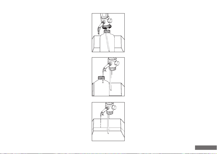
- Titriervorgang beenden, Verschlusskappe
aufstecken und Gerät ausschalten.
- Auf Vorratsflasche montiertes Gerät in
Reinigungsbehälter stellen.
- Gerät mittels geeignetem Handschutz von
Vorratsflasche abschrauben und heraus nehmen (Ansaugschlauch ragt nicht mehr
in die Flüssigkeit) Achtung: Aus dem Ansaug-
schlauch kann Flüssigkeiten austreten!
- Ausstoßeinheit über Öffnung Vorratsflasche
halten.
- Verschlusskappe abziehen und nach
hinten in Aufbewahrungsposition schieben.
- Gerät einschalten und Taste „Entlüften“ so oft
drücken, bis keine Flüssigkeit mehr austritt.
- Terminate titration, fit the closure cap and
deactivate the unit.
- Place the unit mounted on a storage bottle
into a cleaning container.
- Using suitable gloves, unscrew the unit from
the storage bottle and remove (the suction
hose no longer sticks into the liquid)
Warning: Liquid may emerge from the
suction hose!
- Hold the ejection unit over the storage
bottle opening.
- Pull off the closure cap and push to the rear
into the retention position.
- Activate the unit. Press “Venting” repeatedly
until no more liquid emerges.
50
Page 51
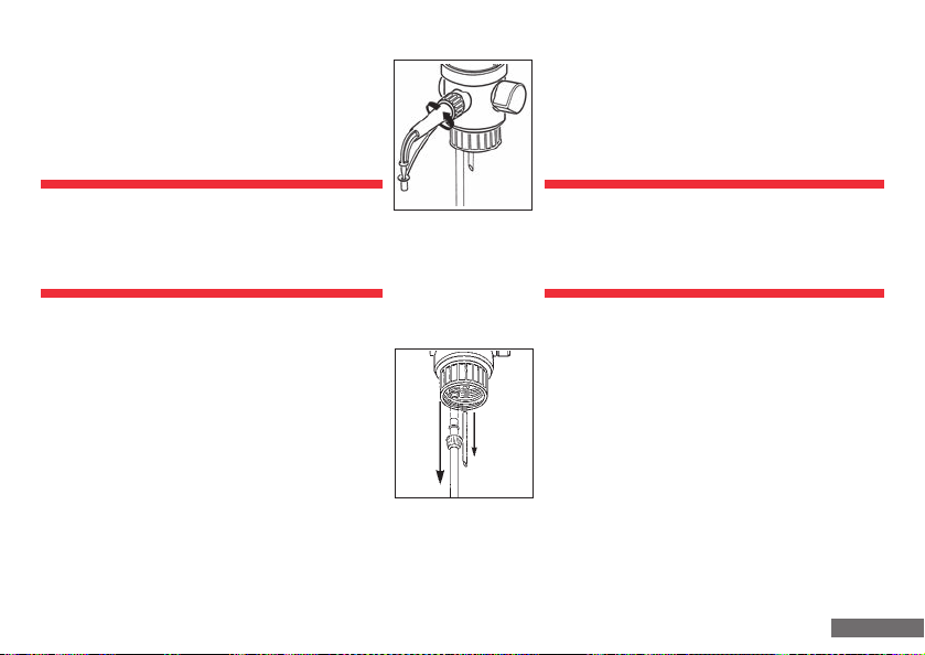
11.2 Grundreinigung mittels Funktion Entlüften
11.2 Basic cleaning with the venting function
- Ansaugschlauch in geeignete Reinigungslösung
eintauchen. Durch Drücken der Taste„Entlüften“
das Gerät komplett durchspülen.
Vorsicht:
- Restliche Flüssigkeit kann spritzen.
- Stets vom Körper weg arbeiten.
- Ansaugschlauch aus Reinigungsmittel herausziehen und Schlauch und Gerät durch die
Funktion „Entlüften“ vollständig leer spülen
(bis keine Flüssigkeit mehr austritt).
- Nachfolgende Teile vom Gerät abnehmen:
- Ausstoßeinheit von dem Gerät abschrauben.
- Rückführschlauch abziehen.
- Überwurfmutter des Ansaugschlauches
lösen und Ansaugschlauch abziehen.
Diese Teile in eine geeignete Reinigungs-
lösung legen.
- Immerse the suction hose in a suitable cleaning
solution. Press the “Venting” button to purge
the unit completely.
Caution:
- Residual liquid may cause splashing.
- Hold away from body at all times.
- Pull the suction hose out of the cleaning
agent and purge the hose and unit with the
“Venting” function until they are completely
empty (until no more liquid emerges).
- Remove the following components from the unit:
- Unscrew the ejection unit from the unit.
- Pull off the recirculation hose.
- Release the union nut on the suction hose
and pull off the suction hose. Immerse
these components in a suitable cleaning
solution.
51
Page 52
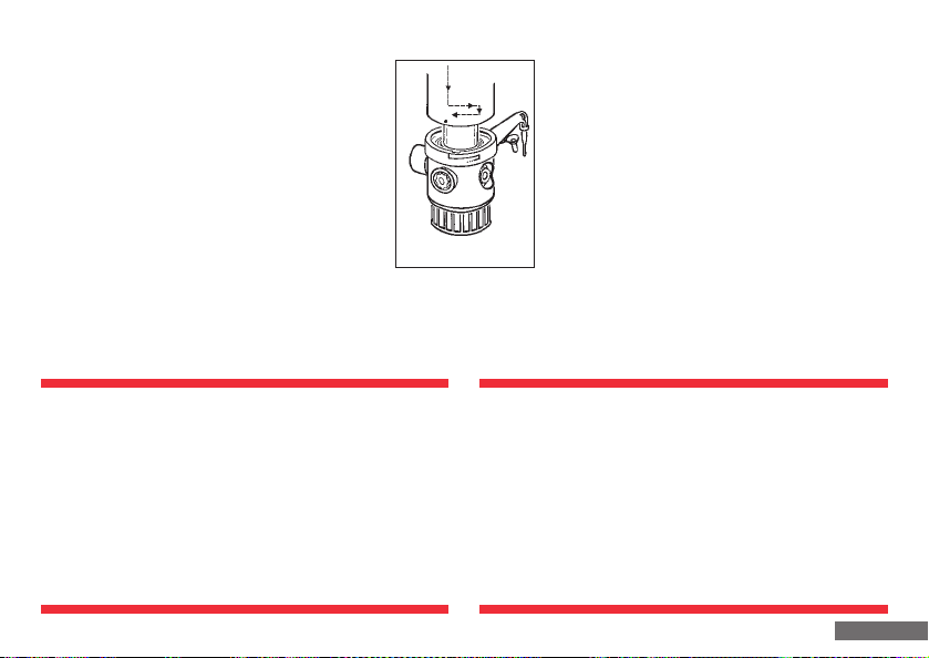
11.3 Intensivreinigung
11.3 Intensive cleaning
- Zuerst Reinigung gemäß Punkt 11.1 und 11.2
durchführen.
- Ventilblock, Zylinder und Kolben ausbauen.
- Geräteoberteil bis zum rechten Anschlag
drehen (Punkt steht in Deckung mit rechter
Kante der Beschriftung auf dem Chromring),
danach 6 mm nach oben ziehen und bis
zum Gegenanschlag nach links drehen.
Wiederum nun Ventilblock mit Zylinder vom
Geräteoberteil nach oben abziehen.
Hinweis!
Gegebenenfalls kann der Kolben durch seitliches Schieben
von der Spindel entfernt werden. Die Spindel wird hierzu mit einem Finger fixiert, mit der anderen Hand kann
der Kolben durch zur Seite schieben von der Spindel
abgekoppelt werden. Für den leichteren Zugang kann
bei Bedarf auch das Sichtfenster heraus genommen
werden.
- Clean first as described in point 11.1. and
11.2.
- Remove the valve block, cylinder and piston.
- Turn the upper part of the unit up to the
right-hand stop (the point is aligned with
the right-hand edge of the inscription on the
chrome ring), then draw 6 mm upwards and
turn to the left up to the left-hand stop. Now
pull the valve block and cylinder upwards
and away from the upper part of the unit.
Note!
The piston can be removed by pushing it sideways
away from the spindle if necessary. The spindle is held
in position with a finger for this purpose, and the piston
can be pushed to the side by hand to disconnect it from
the spindle. For greater ease of access, the inspection
window can also be removed if necessary.
52
Page 53
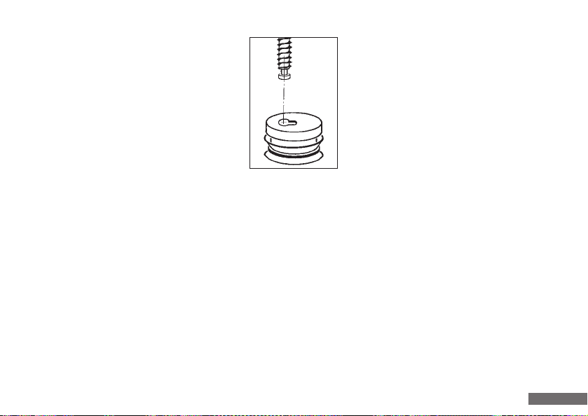
11.3 Intensivreinigung
Steht die Basiseinheit in der Reinigungsposition,
kann die Spindel durch längeres Drücken und
Halten der „Move“-Taste in der Meldung in der
Bedieneinheit langsam bis zum unteren Anschlag
gefahren werden, um die Kolbenmontage zu
erleichtern. Steht die Spindel bereits ganz unten
fährt diese durch längeres Drücken der Taste
wieder leicht nach oben.
11.3 Intensive cleaning
If the basic unit is in the cleaning position,
position mounting can be facilitated by moving
the spindle slowly to the lower stop by pressing
the “Move“ button in the message on the
control unit for a longer period of time. If the
spindle is already in the lowermost position,
it can be raised easily by pressing the button
again for a longer period of time.
- Kolben auf Beschädigungen der Dichtlippen überprüfen
(gegebenenfalls austauschen) und zu den unter Punkt
11.2 aufgelisteten Teilen in die Reinigungslösung legen.
- Zylinder mit Bürste und Reinigungslösung reinigen und
mit Spüllösung nachspülen.
- Kolben, Ventilblock und Zylinder wieder einbauen.
- Kolben auf Spindel aufschieben.
- Geräteoberteil auf Ventilblock mit Zylinder aufstecken.
Markierung auf Geräteoberteil mit linker Kante der
Markierung auf dem Chromring zur Deckung bringen.
- Check the piston for damage to the seal lips (replace if
necessary) and deposit in the cleaning solution with the
components listed in point 11.2.
- Clean the cylinder with a brush and cleaning solution
and rinse with a rinsing solution.
- Remount the piston, valve block and cylinder.
- Push the piston onto the spindle.
- Fit the upper part of the unit onto the valve block and
cylinder. Align the marking on the upper part of the unit with
the left-hand edge of the marking on the chrome ring.
53
Page 54
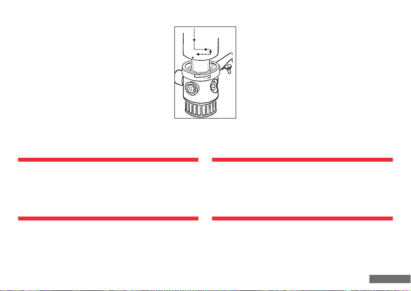
11.3 Intensivreinigung
11.3 Intensive cleaning
- Geräteoberteil 6 mm bis zum ersten Anschlag
auf Ventilblock mit Zylinder einschieben und
bis zum rechten Anschlag drehen, danach um
weitere 6 mm zusammenschieben.
- Auslaufeinheit jetzt in gewünschte Arbeits-
position bringen.
- Funktion des Gerätes prüfen.
Achtung!
Kolben vorsichtig in den Glaszylinder einstecken, da
sonst die Dichtlippe beschädigt werden könnte. Dies
hätte eine Undichtigkeit des Systems zur Folge!
- Push the upper part of the unit 6 mm onto
the valve block and cylinder up to the first
stop and turn to the right-hand stop, pushing
a further 6 mm together subsequent to this.
- Now turn the ejection unit to the desired
position.
- Check the function of the unit.
Warning!
Insert the piston carefully into the glass cylinder, as
the seal lip can otherwise be damaged. This will cause
the system to leak!
54
Page 55

12. Sterilisation
12. Sterilisation
Die medienführenden Teile des Gerätes sind dampfsterilisierbar und beständig bis 121 °C bei einer Einwirkzeit nach
DIN te = 20 min.
Achtung:
Nur folgende Teile dürfen dampfsterilisiert werden:
- Ventilblock mit Zylinder
- Ansaugschlauch
- Auslaufeinheit
- Rückführschlauch
- Kolben
Geräteoberteil, Bedieneinheit und Netzteil keinesfalls
dampfsterilisieren! (siehe Einzelteilübersicht Punkt 2).
The components in the unit conveying media are resistant
to steam sterilisation up to 121 °C and an exposure time
conforming to DIN te = 20 min.
Warning:
Only the following components should be steam sterilised:
- Valve block with cylinder
- Suction hose
- Ejection unit
- Recirculation hose
- Piston
The upper part of the unit, control unit and power supply
unit should never be sterilised with steam!
(see point 2 for overview of individual components).
55
Page 56

12.1 Vorbereitung
12.1 Preparation
Vor Sterilisation Reinigung durchführen (siehe Punkt 11).
12.2 Demontage
Hinweis:
Die Demontage kann nur in Grundstellung (Kolbenein heit steht ganz unten) erfolgen. Gerät darf nur im
ausgeschalteten Zustand demontiert werden!
Neben den in Punkt 11.1 aufgeführten Teilen werden die
anderen medienführenden Teile des Gerätes, wie in Punkt
11.2 beschrieben, demontiert und gereinigt.
Cleaning should be realized prior to sterilisation (see point 11).
12.2 Dismantling
Note:
Dismantling can only be realized in the home position
(the piston unit is in the lowest position). The unit
should only be dismantled when deactivated!
In addition to the components listed in point 11.1. the
other unit components conveying media described in point
11.2. are dismantled and cleaned.
56
Page 57
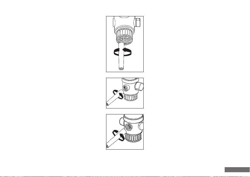
12.3 Ansaug-, Ausstoß- und Rückführventile
lockern
12.3 Loosening the suction, ejection and
recirculation valve
- Ansaugschlauch demontieren.
- Ausstoßeinheit demontieren.
- Ansaugventil mit Montageschlüssel durch
halbe Drehung gegen den Uhrzeigersinn
lockern.
- Ausstoßventil mit Montageschlüssel durch
halbe Drehung gegen den Uhrzeigersinn
lockern.
- Rückführventil mit Montageschlüssel durch
halbe Drehung gegen den Uhrzeigersinn
lockern.
- Disconnect the suction hose.
- Disconnect the ejection unit.
- Loosen the suction valve with the assembly
wrench by turning it counterclockwise a half
a revolution.
- Loosen the ejection valve with the assembly
wrench by turning it counterclockwise a half
a revolution.
- Loosen the recirculation valve with the
assembly wrench by turning it counterclock-
wise a half a revolution.
57
Page 58
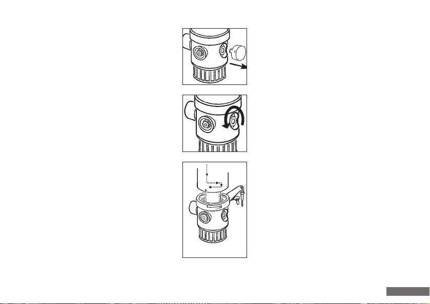
12.3 Ansaug-, Ausstoß- und Rückführventil lockern
12.3 Loosening the suction, ejection and recirculation valve
- Deckel seitlich greifen und abziehen.
- Mutter gegen den Uhrzeigersinn eine halbe
Umdrehung öffnen und durch Druck auf die
Mutter den Hahn lockern, Demontage des
Kolbens.
- Kolben durch zur Seite schieben von der
Spindel abkoppeln (siehe Punkt 11.3.)
- Grasp the cover laterally and pull off.
- Open the nut in a counterclockwise direction
by turning it half a revolution, and loosen
the tap by applying pressure to the nut and
dismantle the piston.
- Disconnect the piston from the spindle by
pushing it to the side (see point 11.3).
58
Page 59
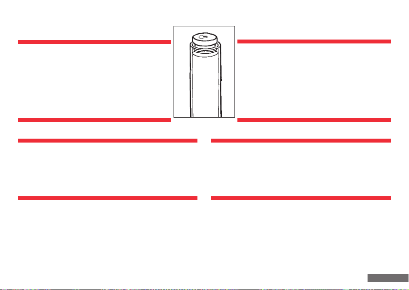
12.3 Ansaug-, Ausstoß- und Rückführventile lockern
12.3 Loosening the suction, ejection and recirculation valves
Wichtig:
Vor der Sterilisation muss der Kolben in
einer entsprechenden Lösung gereinigt
werden. Dann Kolben so weit in den Glas zylinder einschieben, dass der Kolben
leicht aus dem Glaszylinder herausragt.
Achtung!
Kolben vorsichtig in Glaszylinder einführen, da sonst die
Dichtlippe beschädigt werden könnte. Dies hätte eine
Undichtigkeit des Systems zur Folge!
Important:
The piston should be cleaned in a suitable
solution prior to sterilisation. Then push
the piston into the glass cylinder to a point
where the piston protrudes slightly out of
the glass cylinder.
Warning!
Insert the piston carefully into the glass cylinder, as the
seal lip can otherwise be damaged. This will cause the
system to leak!
59
Page 60
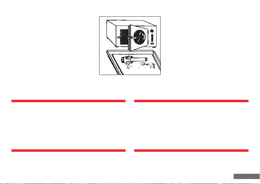
12.4 Sterilisation durchführen
12.4 Sterilisation procedure
Dampfsterilisation aller medienführenden
Teile durchführen (bis 121°C, Einwirkzeit
nach DIN te = 20 min).
Achtung!
- Gerät auf Raumtemperatur abkühlen lassen und
erst danach mit dem Zusammenbauen beginnen.
- Alle Teile auf Beschädigung prüfen und ggf. aus-
tauschen.
Realize steam sterilisation of all components conveying media (up to 121 °C,
exposure time conforming to DIN
te = 20 min).
Warning!
- Allow the unit to cool to room temperature and
only then commence reassembly.
- Check all components for damage and replace if
necessary.
60
Page 61
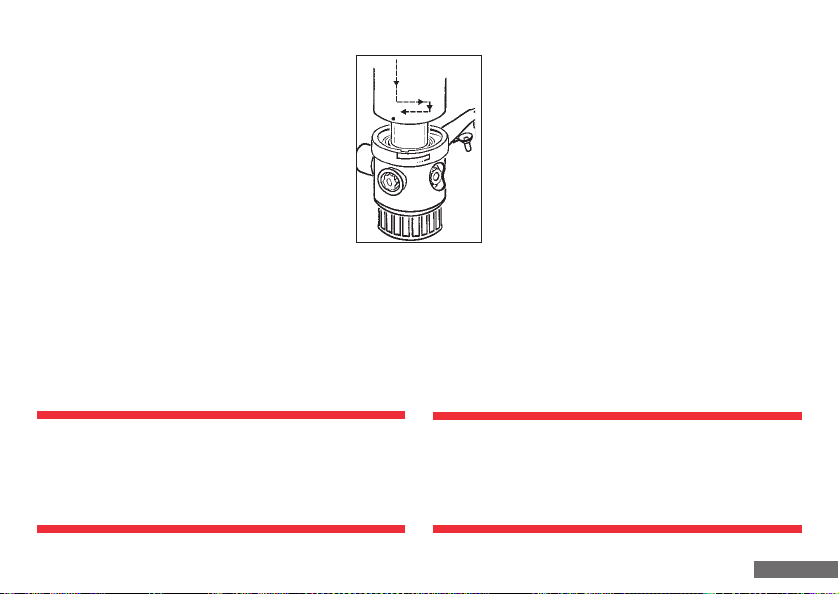
12.5 Montage
12.5 Assembly
Kolben, Ventilblock und Zylinder wieder einbauen:
Geräteoberteil auf Ventilblock mit Zylinder
aufstecken. Markierung auf Geräteoberteil mit
linker Kante der Markierung auf den Chromring
zur Deckung bringen. Geräteoberteil 6 mm bis
zum ersten Anschlag auf Ventilblock mit Zylinder
einschieben und bis um rechten Anschlag drehen,
danach um weitere 6 mm zusammenschieben.
Auslaufeinheit jetzt in gewünschte Arbeitsposition
bringen.
Achtung!
Kolben vorsichtig in Glaszylinder einstecken, da sonst
die Dichtlippe beschädigt werden könnte. Dies hätte
eine Undichtigkeit des Systems zu Folge!
Remount the piston, valve block and cylinder:
Fit the upper part of the unit onto the valve and
cylinder. Align the marking on the upper part of
the unit with the left-hand edge of the marking
on the chrome ring. Push the upper part of the
unit 6 mm onto the valve block and cylinder up
to the first stop, pushing a further 6 mm together
subsequent to this. Now turn the ejection unit to
the desired position.
Warning!
Insert the piston carefully in the glass cylinder, as
the seal lip can otherwise be damaged. This will cause
the system to leak!
61
Page 62
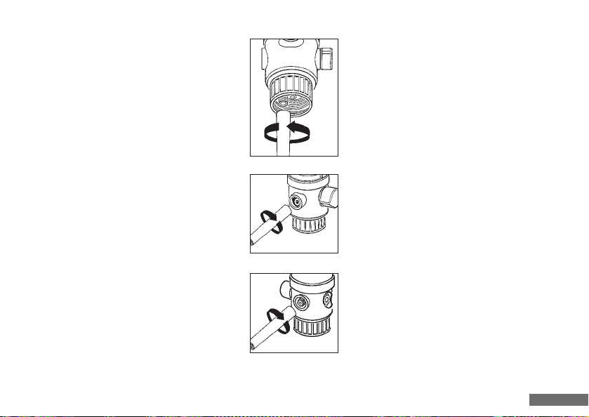
12.6 Ansaug-, Ausstoß- und Rückführventil
festdrehen
12.6 Tightening the suction, ejection and
recirculation valve
- Ansaugventil mit Montageschlüssel im
Uhrzeigersinn festdrehen.
- Ausstoßventil mit Montageschlüssel im
Uhrzeigersinn festdrehen.
- Rückführventil mit Montageschlüssel im
Uhrzeigersinn festdrehen.
- Tighten the suction valve firmly with the
assembly wrench by turning it in a clockwise
direction.
- Tighten the ejection valve firmly with the
assembly wrench by turning it in a clockwise
direction.
- Tighten the recirculation valve firmly with
the assembly wrench by turning it in a clockwise direction.
62
Page 63
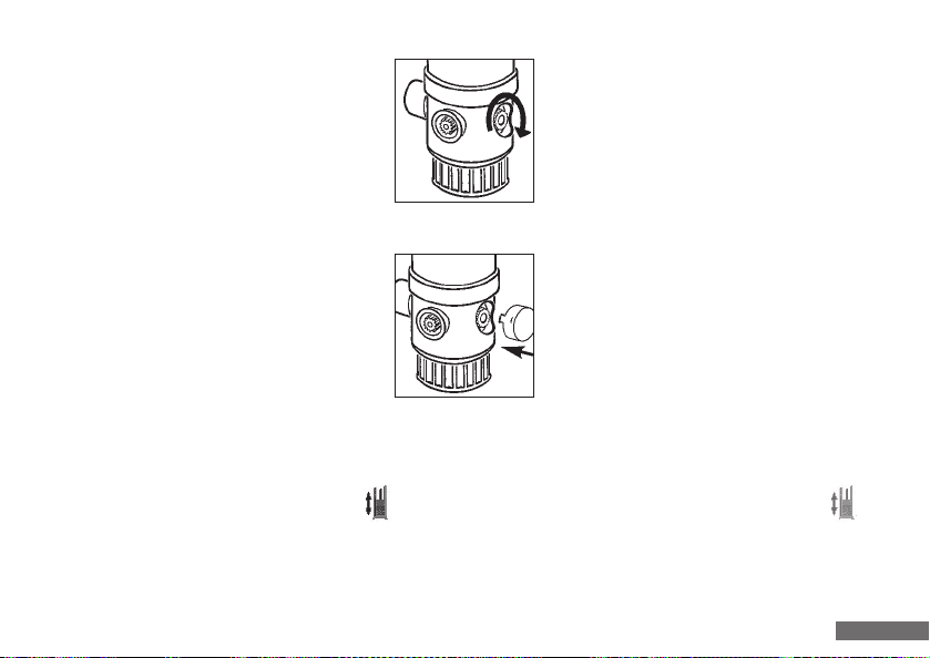
12.6 Ansaug-, Ausstoß- und Rückführventil festdrehen
12.6 Tightening the suction, ejection and recirculation valve
- Mutter auf dem Ventilhahn im Uhrzeiger sinn von Hand anziehen.
- Deckel aufstecken.
12.7 Funktionsprüfung
- Gerät einschalten.
- Funktionsprüfung über Symbol „Entlüften“ .
Entlüftungsfunktion muss erfolgen (auch ohne
Flüssigkeit ausführbar).
- Bei Störungen bitte beim Problemlösungen nachsehen
(siehe Punkt 16) oder an Hersteller wenden.
- Tighten the nut on the valve tap by hand by
turning it in a clockwise direction.
- Fit the cover.
12.7 Function inspection
- Activate the unit.
- Function inspection with the “Venting” symbol .
The venting function should be realized (can even be
realized without liquid).
- Please check “Trouble-shooting” in case of malfunction
(see point 16) or contact the manufacturer.
63
Page 64
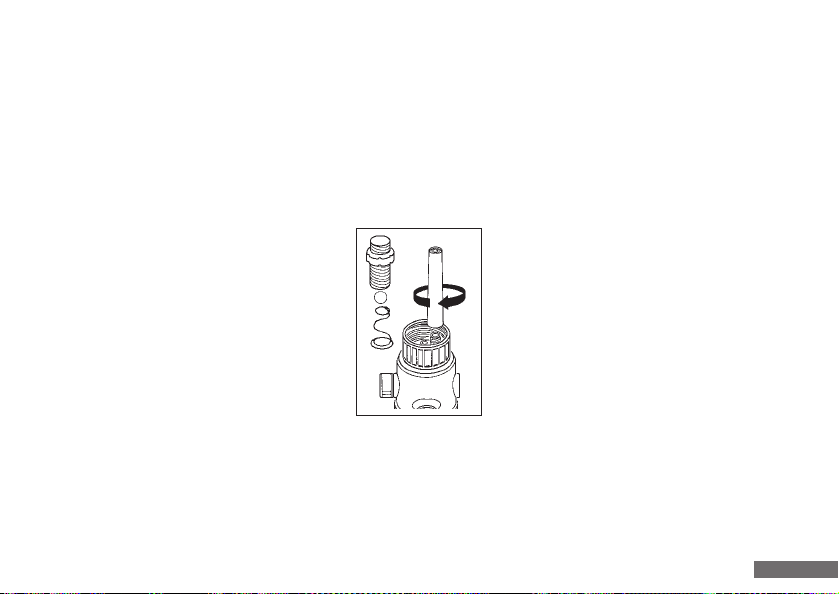
13. Ventile auswechseln
13. Valve replacement
Undichte oder beschädigte Ansaug-, Ausstoß- und Rückführventile sind sofort auszuwechseln (siehe „Zubehör und
Ersatzteile“ Punkt 19).
13.1 Ansaugventil auswechseln
- Reinigung durchführen (siehe Punkt 11).
- Ansaugschlauch abschrauben.
- Gerät auf den Kopf stellen, damit Ventilkugel
bei Austauschvorgang nicht herausfällt.
- Ansaugventil mit Montageschlüssel heraus schrauben und die Ventilkugel herausnehmen.
- Kugel wieder einsetzen und neues Ansaugventil
einschrauben und mit Montageschlüssel festdrehen.
- Ansaugschlauch bis zum Anschlag aufstecken und
Überwurfmutter festdrehen (siehe Punkt 6.2).
Leaking or damaged suction, ejection and recirculation
valves should be replaced immediately (see “Accessories
and spare parts” in point 19)
13.1 Suction valve replacement
- Realize cleaning (see point 11).
- Unscrew the suction hose.
- Stand the unit on its head to prevent the
valve ball falling out during replacement.
- Unscrew the suction valve with the assembly
wrench and remove the valve ball.
- Insert the ball again and screw on the new
suction valve, tightening with the assembly
wrench.
- Push on the suction hose up to the stop and
tighten the union nut firmly (see point 6.2).
64
Page 65
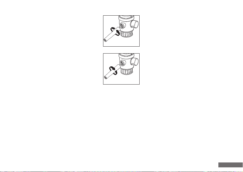
13.2 Ausstoßventil auswechseln
13.2 Ejection valve replacement
- Reinigung durchführen (siehe Punkt 11).
- Ausstoßeinheit abschrauben.
- Ausstoßventil mit Montageschlüssel
herausschrauben und entfernen.
- Neues Ausstoßventil einschrauben und mit
Montageschlüssel festdrehen.
- Ausstoßeinheit bis zum Anschlag aufstecken
und Überwurfmutter gut festdrehen.
Auf festen Sitz achten!
13.3 Rückführventil auswechseln
- Rückführventil mit Montageschlüssel herausschrauben
und entfernen.
- Neues Rückführventil einschrauben und mit Montage-
schlüssel festdrehen.
- Realize cleaning (see point 11).
- Unscrew the ejection unit.
- Screw out the ejection valve with the
assembly wrench and remove.
- Screw in the new ejection valve and tighten
firmly with the assembly wrench.
- Push on the ejection unit up to the stop and
tighten the union nut firmly.
Check to ensure a secure fitting!
13.3 Recirculation valve replacement
- Unscrew the recirculation valve with the assembly
wrench and remove.
- Screw in the new recirculation valve and tighten firmly
with the assembly wrench.
65
Page 66

14. Reparatur beim Hersteller
14. Repair by manufacturer
- Vor Einsendung eines defekten Gerätes, ist es vom
Anwender sorgfältig zu reinigen (siehe Punkt 11).
- Geräte werden nur dann repariert, wenn diese vom
Anwender gereinigt und mit keinerlei gesundheits-
gefährdeten Stoffen kontaminiert sind.
- Ungereinigte Geräte gehen unrepariert an den Absender zurück!
- Aufgetretene Störung genau beschreiben.
- Verwendete Flüssigkeit angeben (wichtig!).
- Wurden andere, als die beschriebenen Eingriffe am
Gerät durchgeführt (z. B. Gewaltanwendung), sind
Garantieleistungen ausgeschlossen.
15. Volumenprüfung
Die unter Punkt 17 angegebenen Parameter für Richtigkeit
(R%) und Variationskoeffizient (CV%) eines Gerätes können
wie folgt geprüft werden:
- A defective unit should be cleaned carefully prior to
sending for repair (see point 11).
- Units will only be repaired if they are cleaned by the
user and are no longer contaminated with any substances which could pose a risk to health.
- Uncleaned units will be returned unrepaired to the sender!
- Describe the malfunction accurately.
- Specify the liquid used (important!).
- The guarantee is rendered null and void if the unit has
been subject to intervention other than those described
(e. g. application of force).
15. Volumetric inspection
The parameters specified in point 17 for the regularity
(R%) and coefficient of variation (CV%) of a unit can be
checked as follows:
66
Page 67

15. Volumenprüfung
15. Volumetric inspection
1. Wiegevorgang (siehe z.B. DIN EN ISO 8655-6)
- Mit dem Gerät das Prüfvolumen (deionisiertes Wasser)
abgegeben.
- Abgegebene Menge auf Analysenwaage wiegen.
- Umrechnen dieser Menge in Volumen.
Achtung: Temperatur, Luftdruck berücksichtigen.
2. Wiederholungswiegung
Um verlässliche Angaben zur Richtigkeit und Variationskoeffizient eines Gerätes zu erhalten, sollte der unter Punkt
1. beschriebene Wiegevorgang mindestens 5 mal wieder-
holt werden.
3. Berechnung von Richtigkeit und Variations-
koeffizient
- Die Richtigkeit (R%) und der Variationskoeffizient (CV%)
des Gerätes sind nach den Formeln der statistischen
Qualitätskontrolle zu berechnen:
1. Weighing procedure (see for example DIN EN ISO 8655-6)
- Dispense the test volume with the unit
(deionised water).
- Weigh the quantity dispensed on the analysis scale.
- Convert this quantity into volume.
Warning: consideration should be given to tempera-
ture and air pressure.
2. Repetitive weighing
The weighing procedure described in 1 should be repeated
at least five times to obtain reliable details on the regularity
and coefficient of variation of a unit.
3. Calculation the regularity and coefficient of variation
- The regularity (R%) and coefficient of variation (CV%)
of the unit should be calculated on the basis of
statistical quality control formulas:
67
Page 68
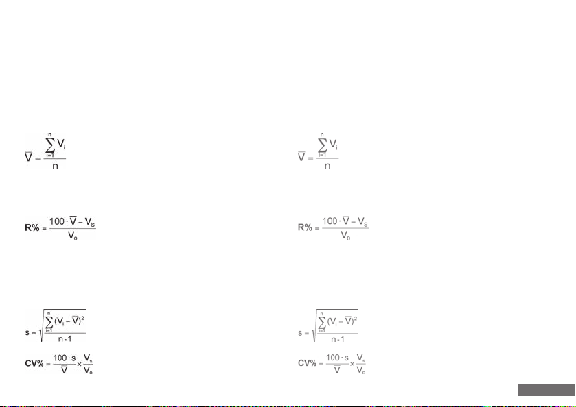
15. Volumenprüfung
15. Volumetric inspection
Überführung der ermittelten Masse in Volumen
V = m · Z
Mittelwertbildung
Systematische Messabweichung (Richtigkeit R%)
Zufällige Messabweichung
(Variationskoeffizient CV%)
Conversion of the mass determined to volume
V = m · Z
Mean value
Systematic measuring deviation (regularity R%)
Random measuring deviation
(coefficient of variation CV%)
68
Page 69

15. Volumenprüfung
15. Volumetric inspection
Legende
m = erhaltener Wägewert in g
V = ermitteltes Volumen in ml
Z = Korrekturfaktor
(z.B.: 1,0029 µl/mg bei 20 °C und 101,3 kPa
1,0040 µl/mg bei 25 °C und 101,3 kPa)
V = Mittelwert Volumen
n = Anzahl der Messungen
= Prüfvolumen
V
s
= Nennvolumen
V
o
S = Standardabweichung
Diese Kurzanleitung stellt lediglich die prinzipielle Vorgehensweise und Berechnung zur Kalibrierung des Gerätes dar.
Die exakte Vorgehensweise ist in der DIN EN ISO 8655
ausführlich dargestellt.
Legend
m = weighed value determined in g
V = volume determined in ml
Z = correction factor
(e.g.: 1.0029 µl/mg at 20 °C and 101.3 kPa
1.0040 µl/mg at 25 °C and 101.3 kPa)
V = mean volume value
n = number of measurement
= test volume
V
s
= nominal volume
V
o
S = standard deviation
This brief guide merely illustrates the principal procedure
and calculation for calibrating the unit. The precise procedure is described in detail in DIN EN ISO 8655.
69
Page 70

16. Problembehandlung
16.1 Meldungen
Befindet sich das Gerät in einem nicht betriebsbereiten Zustand, wird dieser durch die rot blinkende LED in der Basiseinheit dargestellt. Weiter zeigt die Bedieneinheit eine entsprechende Warnmeldung:
Meldungen Grund Lösung
Kolbenblockade, Basiseinheit - Rückführhebel nicht am Anschlag - Rückführhebel ganz nach vorne oder
überprüfen hinten drehen.
- Ventile sind verstopft - Ventile reinigen oder austauschen.
- Viskosität der Flüssigkeit zu hoch - Langsamere Geschwindigkeit wählen,
Dosierspitze statt Titrierspitze
verwenden.
- Verschlusskappe ist nicht - Verschlusskappe abnehmen.
abgenommen
Gerät steht in Reinigungsposition, - Oberteil der Basiseinheit ist zum - Oberteil etwas nach links dehen.
Ventilblock nicht eingebaut rechten Anschlag (Demontage position) gedreht
- Oberteil der Basiseinheit ist - Basiseinheit wieder zusammenbauen.
demontiert
70
Page 71

16.1 Meldungen
Meldungen Grund Lösung
Keine Basiseinheit erkannt - Basiseinheit ist nicht mit - Kabelverbindung überprüfen.
Bedieneinheit verbunden
Kein Kolben eingebaut - Basiseinheit wurde ohne Kolben - Basiseinheit auseinander nehmen und
zusammen gebaut Kolben wieder einsetzen.
Sonderfall Reinigungsposition:
Steht die Basiseinheit in der Reinigungsposition, kann die Spindel durch längeres Drücken und Halten der „Move“-Taste in
der Meldung in der Bedieneinheit langsam bis zum unteren Anschlag gefahren werden, um die Kolbenmontage zu
erleichtern. Steht die Spindel bereits ganz unten, fährt diese durch längeres drücken der Taste wieder leicht nach oben.
71
Page 72

16. Trouble-shooting
16.1 Messages
The red flashing LED in the basic unit indicates that the unit is in a non-operational condition. The control unit also
generates a suitable warning message:
Messages Reason Solution
Piston blockage, check basic unit - Recirculation lever not applied to - Turn the recirculation lever
stop completely to the front or rear.
- Valves are blocked - Clean or replace valves.
- Liquid viscosity is too high - Select slower speed, use dispensing
tip instead of titration tip.
- Closure cap is not removed - Remove closure cap.
Unit is in cleaning position, - Upper part of basic unit is turned to - Turn the upper part slightly to the left.
valve block is not fitted the right-hand stop
(dismantling position)
- Upper part of basic unit has been - Assembly basic unit again.
dismantled
72
Page 73

16.1 Messages
Messages Reason Solution
No basic unit identified
unit
- B
asic unit not connected to control -
Check cable c
onnection.
on fitted
No pist
asic unit was assembled without -
- B
on
pist
tle basic unit and fit piston
Disman
again.
Special cle
aning position case:
If the basic unit is in cleaning position, mounting can be facilitated by moving the spindle slowly to the lower stop by
pressing the “Move“ button in the message on the control unit for a longer period of time. If the spindle is already at the
lowest point, pressing the button for a longer period will move it slightly upwards again.
73
Page 74

16.2 Sonstige Probleme – Lösungen
Lässt sich das Gerät nicht mehr bedienen, kann es durch langes Drücken und Halten (ca. 10 s) in die rechte obere Ecke des
Touchscreens (Position des Akkusymbols) ausgeschaltet werden. Alle seit dem letzten Einschalten gemachten Änderungen
gehen dabei verloren, daher sollte diese Funktion nur im Notfall benutzt werden.
Problem Grund Lösung
Aus dem Spalt zwischen Ansaug-, - Ventile locker oder beschädigt - Ventile mit Montageschlüssel festAusstoß-, Rückführventil und Ventil- ziehen oder ggf. austauschen.
block tritt Flüssigkeit aus Achtung: nach Sterilisation müssen
Ansaug-, Ausstoß- und Rückführ ventil mit Montageschlüssel fest gezogen werden.
Zwischen Ausstoßventil und Ausstoß- - Ausstoßeinheit locker oder - Original-Ausstoßeinheit richtig
einheit tritt Flüssigkeit aus beschädigt montieren.
- Falsche Ausstoßeinheit - Nur Original-Ausstoßeinheit
verwenden.
Gerät saugt Luft an - Gerät nicht entlüftet - Gerät entlüften
- Ansaugschlauch locker - Ansaugschlauch festdrehen
- Ansaugschlauch bzw. Überwurfmutter - Ansaugschlauch wechseln
beschädigt
74
Page 75

16.2 Sonstige Probleme – Lösungen
Problem Grund Lösung
Am Rückführventil (Rückseite des - Rückführventil locker oder - Rückführventil mit Montageschlüssel
Gerätes) tritt Flüssigkeit aus beschädigt festziehen oder ggf. austauschen.
Zwischen Ventilwelle und Ventilblock - Ventilblock locker - Mutter auf Ventilwelle festziehen.
tritt Flüssigkeit aus (nur bei abgenommenem Deckel erkennbar)
Dosiervolumen fehlerhaft - Ausstoßeinheit locker oder - Original-Ausstoßeinheit richtig mon beschädigt tieren. Nur Original-Ausstoßeinheit
verwenden.
- Ansaugschlauch locker oder - Ansaugschlauch festdrehen.
beschädigt
- Ansaug-, Ausstoß- und Rückführ- - Ventil mit Montageschlüssel fest ventil locker oder beschädigt ziehen oder ggf. ausstauschen -
Reinigung durchführen.
75
Page 76

16.2 Sonstige Probleme – Lösungen
Problem Grund Lösung
Flüssigkeit steht über Kolbeneinheit - Beschädigte Dichtlippen an - Kolbeneinheit austauschen.
Kolbeneinheit
Luftblasen im Glaszylinder sichtbar - Gerät nicht entlüftet - Gerät entlüften.
- Ansaugschlauch oder Überwurf- - Ansaugschlauch festdrehen.
mutter locker, deformiert Original-Ansaugschlauch wechseln.
Dosiervolumen ungenau - Dichtlippe der Kolbeneinheit beschädigt - Komplette Kolbeneinheit austauschen.
- Ausstoßeinheit locker oder - Ausstoßeinheit richtig montieren.
beschädigt
Fehlerhafte Werte in der Anzeige - Gerätefehler - Gerät über entspechende Taste
im Menüpunkt „Hauptmenü“ auf
Werkseinstellung zurücksetzen.
76
Page 77

16.2 Other problems – solutions
If the unit can no longer be operated, it can be deactivated by pressing and holding (approx. 10 s) in the upper right-hand
corner of the touch screen (battery symbol position) for a longer period. All changes realized since the last activation are
lost as a result, so this function should only be used in emergencies.
Problem Reason Solution
Liquid emerges from the gap between - Valves loose or damaged - Tighten the valves firmly with the
the suction, ejection or recirculation assembly wrench or replace if necessary.
valve and valve block Warning: the suction, ejection, and
recirculation valve should be
tightened firmly with the assembly
wrench after sterilisation.
Liquid emerges between the ejection - Ejection unit loose or damaged - Mount original ejection unit correctly.
valve and ejection unit
- Incorrect ejection unit - Use only original ejection unit.
Unit is suctioning in air - Unit not vented - Vent unit.
- Suction hose loose - Tighten suction hose firmly.
- Suction hose and/or union nut - Replace suction hose.
damaged
77
Page 78

16.2 Other problems - solutions
Problem Reason Solution
Liquid emerges from recirculation - Recirculation valve loose or - Tighten recirculation valve firmly with
valve (rear of unit) damaged the assembly wrench or replace.
Liquid emerges between the valve - Valve shaft loose - Tighten nut on valve shaft firmly.
shaft and valve block (only visible
when cover is removed
Erroneous dispensing volume - Ejection unit loose or damaged - Mount original ejection unit correctly.
Use only orginal ejection unit.
- Suction hose loose or damaged - Tighten suction hose firmly.
- Suction, ejection and recirculation - Tighten the valves firmly with the
valves loose or damaged assembly wrench or replace if necessary.
Realize cleaning.
78
Page 79

16.2 Other problems - solutions
Problem Reason Solution
Liquid over piston unit
Visible air bubbles in glass cylinder -
- D
amaged seal lip on piston unit - Replace piston unit.
t vented
Unit no
- Suc
tion hose or union not loose, -
ent unit.
- V
Tigh
ten suction hose firmly.
deformed Change original suction hose.
Inaccurate dispensing volume
- Pist
on unit seal lip damaged
- R
eplace complete piston unit.
- Ejection unit loose or damaged - Mount ejection unit correctly.
Errenous values on display
- Unit error - R
eset unit to default settings using
the butt
on in the “Main menu” item .
79
Page 80

16.3 Herstellerkontakt
16.3 Contacting the manufacturer
Sollte durch vorher beschriebene Maßnahmen der Fehler
nicht vollständig beseitigt werden können, so ist der
Händler oder Hersteller unter Angabe der Seriennummer
und der Revisionsnummer der Basiseinheit sowie der
Bedieneinheit zu kontaktieren. Die Seriennummern sind
auf den Geräteteilen eingeprägt und im Info Menü abzulesen,
die Revisionsnummern nur im Info-Menü.
Should the measures as listed above fail to completely
remedy the malfunction, the dealer or manufacturer should
be contacted. Please specify the serial number and revision
number of the basic unit and control unit. Serial numbers
are embossed on unit components and can be viewed in
the Info menu. Revision numbers can only be viewed in
the Info menu.
80
Page 81
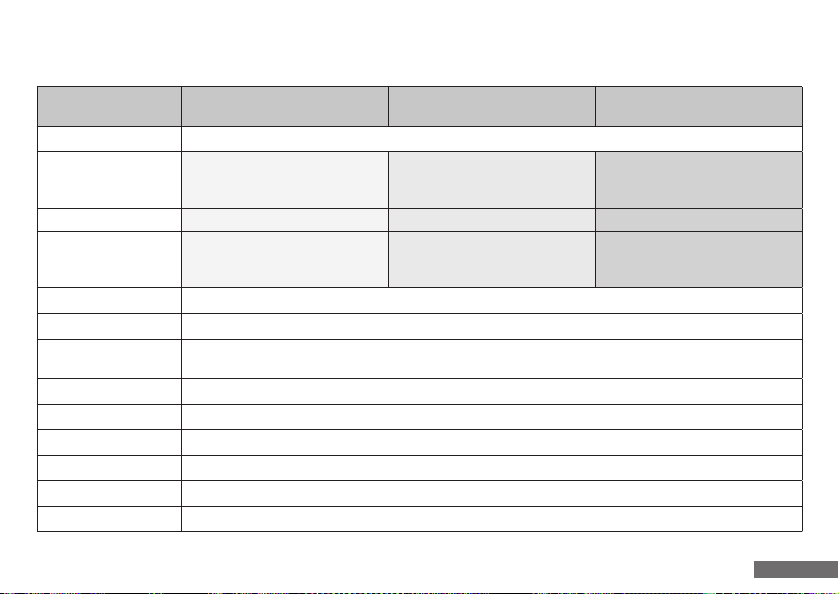
17. Technische Daten
Leistungsdaten
Basiseinheit 10 ml 20 ml 50 ml
Geräte-Typ mikroprozessgesteuertes, motorisches Kolbenhubsystem mit Rückführung
Volumenbereich
Volumengenauigkeit R = 0,2%, CV = 0,07% R = 0,2%, CV = 0,07% R = 0,2%, CV = 0,05%
Geschwindigkeit
Arbeitstemperaturbereich 4 °C bis 40 °C
Stromversorgung Steckernetzteil 15 V, 1 A (optional über Akku in Bedieneinheit)
Optionaler Akkubetrieb
Materialien Gehäuse aus PA6 glasfaserverstärkt, alle Flüssigkeit berührenden Teile aus chemisch inertem Material
Reinigung, Sterilisation motorische Spülfunktion, ohne Werkzeug entkuppelbar, medienführende Teile dampfsterilisierbar (121 °C)
Entlüftung automatisch auf Knopfdruck
Abmessung/Gewicht 320 mm x 80 mm x 63 mm (H x T x B)/ 660 g
Qualitätskontrolle gemäß DIN EN ISO 8655
Dokumentation DIN EN ISO 9001 gerechte Zertifizierung, durch Geräteprotokoll mit Seriennummer
0,01 ml - 10,00 ml bzw. 0,010 ml - 10,000 ml
(max. Kolbenhub 10 ml, automatisch
addierend), Auflösung: 1 µl
in 16 Stufen von 0,01 ml/s bis 2 ml/s
unabhängig für Ansaug- und Abgabegeschwindigkeit einstellbar
Akkuladung für durchschnittlich 2,5 bis 3 h Dauerbetrieb. Akku-Kapazität im TFT-Display angezeigt, Ladezeit 6,5 h,
intelligente Elektronik verhindert Überladung und Tiefentladung
0,1 ml - 20 ml
(max. Kolbenhub 20 ml, automatisch
addierend), Auflösung: 10 µl
in 10 Stufen von 0,1 ml/s bis 4 ml/s
unabhängig für Ansaug- und Abgabegeschwindigkeit einstellbar
1,00 ml - 50 ml
(max. Kolbenhub 50 ml, automatisch
addierend), Auflösung: 10 µl
in 10 Stufen von 1 ml/s bis 10 ml/s
unabhängig für Ansaug- und Abgabegeschwindigkeit einstellbar
81
Page 82
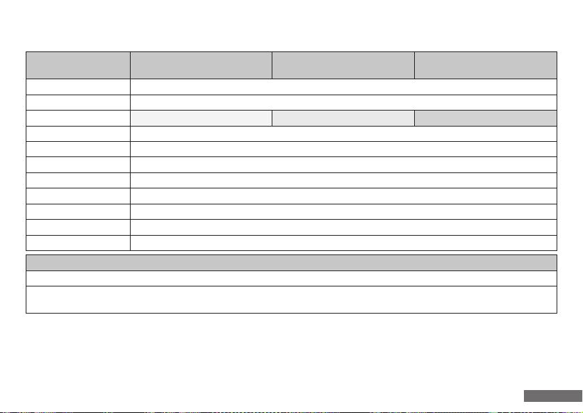
17. Technische Daten
Leistungsdaten
Bedieneinheit 10 ml 20 ml 50 ml
Modul-Typ externes Bedienmodul inkl. Touchscreen Bedienung
Touchscreen 3,5" mit 320 x 240 Pixel, wichtigste Funktionen vom Hauptbildschirm direkt zu erreichen
Volumenvorwahl-Titration bis zu 10 ml bis zu 20 ml bis zu 50 ml
Schnelltitration zur raschen Medienabgabe bei Beginn des Titrationsvorganges
Tropfentitration mit 1 Tropfen pro Tastendruck schneller werdend bei gedrückter Taste
Quick-Cal Kalibrierung auf andere Temperatur oder anderes Medium möglich
Methodenspeicher bis zu 9 unterschiedliche Geräteeinstellungen speicherbar
Sprachen 4 Sprachen (D, GB, F, ES) standardmäßig integriert
PC Schnittstelle USB oder RS232
Fernsteuerung über kabelgebundene Zusatzgeräte kann das Gerät ferngesteuert werden
Abmessungen/Gewicht 55 mm x 130 mm x 110 mm (H x Tx B) /230 g
Lieferumfang
Gerät mit A45 Innengewinde und zusätzlichen Gewindeadaptern A 32, A 38 und S 40
Ansaugschlauch mit Überwurfmutter, Rückführschlauch, Ausstoßeinheit Titration, Ventil-Montageschlüssel, Touch-Screen-Bedieneinheit,
braunes Lichtschutzfenster, Netzteil mit Stecker EU, US, UK, Data Power Kabel, Bedienungsanleitung und Einzel-Qualitätszertifikat
Das Netzteil kann in der jeweiligen landesspezifischen Ausführung im Lieferumfang abweichen.
82
Page 83
17. Technical data
Performance data
Basic unit 10 ml 20 ml 50 ml
Unit type Microprocessor-controlled, motorised piston lift system with recirculation
Volume range
Volume accuracy R = 0.2%, CV = 0.07% R = 0.2%, CV = 0.07% R = 0.2%, CV = 0.05%
Velocity
Operating temperature range 4 °C to 40 °C
Power supply Plug-in mains unit 15V, 1 A (optional via battery in control unit)
Optional battery operation
Materials Housing made of PA6 reinforced glass fibre, all parts in contact with liquid are made of chemically inert material
Cleaning, sterilisation Motorised rinsing function, can be disconnected without tools, media-conveying components are suitable for steam sterilisation (121 °C)
Aeration Automatic at the push of a button
Dimensions/Weight 320 mm x 80 mm x 63 mm (H x D x W)/ 660 g
Quality control in compliance with DIN EN ISO 8655
Documentation DIN EN ISO 9001 compliant certification through unit protocol with serial number
0.01 ml - 10.00 ml and 0.010 ml - 10.000 ml
(max. piston lift 10 ml, automatic addition),
resolution: 1 µl
in 16 stages from 0.01 ml/s to 2 ml/s
independently adjustable for suctioning
and dispensing speed
Battery charge for an average of 2.5 to 3 h continuous operation. Battery capacity indicated on TFT display, charging time 6.5 h,
intelligent electronics prevent overloading and deep discharging.
0.1 ml - 20 ml
(max. piston lift 20 ml, automatic addition),
resolution: 10 µl
in 10 stages from 0.1 ml/s to 4 ml/s
independently adjustable for suctioning
and dispensing speed
1.00 ml - 50 ml
(max. piston lift 50 ml, automatic addition),
resolution: 10 µl
in 10 stages from 1 ml/s to 10 ml/s
independently adjustable for suctioning
and dispensing speed
83
Page 84
17. Technical data
Performance data
Control unit 10 ml 20 ml 50 ml
Module type External control module incl. touch screen control
Touchscreen 3.5“ with 320 X 240 pixel, most important functions directly accessible from main screen
Titration volume preselection Up to 10 ml Up to 20 ml Up to 50 ml
Rapid titration For rapid medium dispensing at beginning of titration process
Droplet titration With 1 droplet per button push, accelerating if button is pressed
Quick-Cal Calibration of other temperature or medium possible
Method memory Up to 9 different unit configurations can be saved
Languages 4 languages (D, GB, F, S) integrated as standard option
PC interface USB or RS232
Remote control Unit can be remotely controlled via an additional cable-connected device
Dimensions/Weight: 55 mm x 130 mm x 110 mm (H x D x W) /230 g
Scope of delivery
Unit with A 45 internal thread and additional A 32, A 38 and S 40 threaded adapters
Suction hose with union nut, recirculation hose, titration ejection unit, valve fitting wrench, touchscreen control unit "titration",
brown light protection window, power supply unit, data power cable, operating manual and individual quality certificate
The power supply unit may derivate from the specific national design in the scope of delivery.
84
Page 85
17. Technische Daten
18. Technical data
Konformität
Konformitätsbescheinigung nach den deutschen Vorschriften der Eichordnung (Anlage 12).
CE
Mit diesem Zeichen wird bestätigt, dass das Gerät den
festgelegten Anforderungen der geltenden EU-Richtlinien
entspricht und dementsprechend geprüft werden.
18. Material
Kolben PTFE Compound
Zylinder Borosilikat Glas 3.3
Ventilblock Halar (ECTFE)
Ventilgehäuse Halar (ECTFE)
Ventilkugel Hochreine Aluminiumoxid-Keramik (99,7%)
Ventilsitz Hochreine Aluminiumoxid-Keramik (99,7%)
Ventilfeder Hastelloy
Conformity
Conformity certificate conforming to German calibration
regulations (appendix 12).
CE
This symbol confirms that the unit meets the stipulated
requirements of pertinent EU directives and is tested in
conformance with these.
18. Materials
Piston PTFE Compound
Cylinder Borosilicate Glass 3.3
Valve block Halar (ECTFE)
Valve mantle Halar (ECTFE)
Valve ball High-purity aluminium oxide ceramic (99.7%)
Valve seat High-purity aluminium oxide ceramic (99.7%)
Valve spring Hastelloy
85
Page 86
19. Zubehör und Ersatzteile
Bestellnummer Order number
Kategorie/Artikelbezeichnung - Category/Article designation
19. Accesories and spare parts
Gewindeadapter - Threaded adapters
931 35 23 PP A 45 auf A 28 - PP A 45 to A 28
931 35 24 PP A 45 auf A 38/430 - PP A 45 to A 38/430
931 36 21 ETFE A 45 auf A 32 - ETFE A 45 to A 32
931 36 23 ETFE A 45 auf A 28 - ETFE A 45 to A 28
931 36 24 ETFE A 45 auf A 38/430 - ETFE A 45 to A 38/430
931 36 25 ETFE A 45 auf A 38 - ETFE A 45 to A 38
931 36 27 ETFE A 45 auf S 40 - ETFE A 45 to S 40
Ventile - Valves
931 60 28
931 60 15
931 65 28
931 65 15
931 66 26
931 66 15
Ausstoßventil, Ventilsitz/Kugel aus hochreiner Keramik (Al
Discharge valve, valve seat/ball made of high purity alumina ceramics (Al2O3 99.7%), spring made of platin-iridium (HF)
Ausstoßventil, Ventilsitz/Kugel aus hochreiner Keramik (Al
Discharge valve, valve seat/ball made of high purity alumina ceramics (Al2O3 99.7%), spring made of Hastelloy
Ansaugventil, Ventilsitz/Kugel aus hochreiner Keramik (Al
Suction valve, valve seat/ball made of high purity alumina ceramics (Al2O3 99.7%), spring made of platin-iridium (HF)
Ansaugventil, Ventilsitz/Kugel aus hochreiner Keramik (Al
Suction valve, valve seat/ball made of high purity alumina ceramics (Al2O3 99.7%), spring made of Hastelloy
Rückführventil, Ventilsitz/Kugel aus hochreiner Keramik (Al
Recirculation valve, valve seat/ball made of high purity alumina ceramics (Al2O3 99.7%), spring made of platin-iridium (HF)
Rückführventil, Ventilsitz/Kugel aus hochreiner Keramik (Al
Recirculation valve, valve seat/ball made of high purity alumina ceramics (Al2O3 99.7%), spring made of Hastelloy
99,7%), Feder aus Platin-Iridium (HF)
2O3
99,7%), Feder aus Hastelloy
2O3
99,7%), Feder aus Platin-Iridium (HF)
2O3
99,7%), Feder aus Hastelloy
2O3
99,7%), Feder aus Platin-Iridium (HF)
2O3
99,7%), Feder aus Hastelloy
2O3
Netzteil - Power supply unit
956 75 01
Die Adapter können in der jeweiligen landesspezifischen Ausführung im Lieferumfang abweichen.
Adapters may deviate from the specific national design in the scope of delivery.
Netzteil (100-240 V) mit Stecker EU, US, UK -
power supply unit (100-240 V) with EU, US UK plug
86
Page 87
20. Vordruck der Unbedenklichkeitsbescheinigung
für Gerät ........................ ..................... (Seriennummer) verwendetes Medium: ..........................................
JA NEIN Wenn JA, bitte definieren
Blut, Körperflüssigkeiten, patholog. Proben
Andere biologische Gefahrenstoffe
Biologisch abbaubare Materialien, die gefährlich werden können
Chemikalien mit gesundheitsgefährdenden Substanzen
Radioaktive Materialien
Andere Gefahren- oder Giftstoffe
Hiermit wird erklärt, dass
- das Gerät vor dem Versand sorgfältig gereinigt und dekontaminiert worden ist,
- keine Gefahren durch Kontamination ausgehen,
- uns bekannt ist, dass bei Schaden durch kontaminierte Geräte Haftungsansprüche gegen uns geltend gemacht
werden können.
Adresse des Einsenders:
Name:
Datum:
Unterschrift:
87
Page 88

20. Clearance certificate form
for unit ............................ .......................(Serial number) Medium used: ..................................................
YES NO Please define in case of YES
Blood, bodily fluids, patholog. samples
Other hazardous biologic substances
Biologically-degradable materials which can pose a risk
Chemicals containing substances harmful to health
Radioactive materials
Other hazardous and toxic substances
We hereby declare that
- the until has been carefully cleaned and decontaminated prior to shipment,
- no risks resulting from contamination exist,
- we are aware that liability claims can be made against us in the event of damage being caused by contaminated units.
Address of sender:
Name:
Date:
Signature:
88
 Loading...