

Page 1

Reference Manual
Web-based Interface
Industrial ETHERNET Switch
RSB20, OCTOPUS OS20/OS24 Managed
RM Web L2B
Release 5.3 05/2012
Technical Support
https://hirschmann-support.belden.eu.com
Page 2

The naming of copyrighted trademarks in this manual, even when not specially indicated, should
not be taken to mean that these names may be considered as free in the sense of the trademark
and tradename protection law and hence that they may be freely used by anyone.
© 2012 Hirschmann Automation and Control GmbH
Manuals and software are protected by copyright. All rights reserved. The copying, reproduction,
translation, conversion into any electronic medium or machine scannable form is not permitted,
either in whole or in part. An exception is the preparation of a backup copy of the software for
your own use. For devices with embedded software, the end-user license agreement on the
enclosed CD applies.
The performance features described here are binding only if they have been expressly agreed
when the contract was made. This document was produced by Hirschmann Automation and
Control GmbH according to the best of the company's knowledge. Hirschmann reserves the right
to change the contents of this document without prior notice. Hirschmann can give no guarantee
in respect of the correctness or accuracy of the information in this document.
Hirschmann can accept no responsibility for damages, resulting from the use of the network
components or the associated operating software. In addition, we refer to the conditions of use
specified in the license contract.
You can get the latest version of this manual on the Internet at the Hirschmann product site
(www.hirschmann.com).
Printed in Germany
Hirschmann Automation and Control GmbH
Stuttgarter Str. 45-51
72654 Neckartenzlingen
Germany
Tel.:+49 1805 141538
RM Web L2B Rel. 5.3 05/2012
Page 3

Contents
Contents
About this Manual 7
Key 9
Opening the Web-based Interface 11
1 Basic Settings 17
1.1 System 18
1.2 Network 22
1.3 Software 25
1.3.1 View the software versions presenton the device 26
1.3.2 TFTP Software Update 26
1.3.3 HTTP Software Update 27
1.4 Port Configuration 28
1.5 Power over ETHERNET 31
1.6 Loading/Saving the Configuration 33
1.6.1 Loading a Configuration 34
1.6.2 Saving the Configuration 34
1.6.3 URL 35
1.6.4 Deleting a configuration 35
1.6.5 Using the AutoConfiguration Adapter (ACA) 36
1.7 Restart 38
2 Security 41
2.1 Password / SNMPv3 access 42
2.2 SNMPv1/v2 Access Settings 45
2.3 Web Access 48
2.3.1 Description of Web Access (http) 48
3Time 51
3.1 SNTP configuration 53
3.2 PTP (IEEE 1588) 57
4 Switching 59
RM Web L2B
Release 5.3 05/2012
3
Page 4

Contents
4.1 Switching Global 60
4.2 Filters for MAC addresses 61
4.3 Multicasts 63
4.3.1 Global Configuration 64
4.3.2 IGMP Querier and IGMP settings 64
4.3.3 Multicasts 66
4.3.4 Settings per Port (Table) 69
5 QoS/Priority 71
5.1 Global 72
5.2 Port Configuration 75
5.2.1 Entering the port priority 76
5.3 802.1D/p mapping 77
5.4 IP DSCP mapping 80
6 Redundancy 83
6.1 Ring Redundancy 84
6.1.1 Configuring the HIPER-Ring 86
6.1.2 Configuring the MRP-Ring 89
6.2 Rapid Spanning Tree 92
6.2.1 Global 94
6.2.2 Rapid Spanning Tree Port 99
7 Diagnostics 103
7.1 Event Log 104
7.2 Ports 105
7.2.1 Statistics table 105
7.2.2 Network load 106
7.2.3 SFP modules 107
7.3 Topology Discovery 108
7.4 Port Mirroring 109
7.5 Device Status 111
7.6 Signal contact 114
7.6.1 Manual Setting 114
7.6.2 Function monitoring 115
7.6.3 Device status 116
7.6.4 Configuring Traps 117
RM Web L2B
4
Release 5.3 05/2012
Page 5

Contents
7.7 Alarms (Traps) 118
7.8 Report 120
7.9 Self Test 121
8 Advanced 123
8.1 DHCP Relay Agent 124
8.2 Command Line 126
A Appendix 127
A.1 Technical Data 128
A.2 List of RFCs 129
A.3 Underlying IEEE Standards 131
A.4 Underlying IEC Norms 132
A.5 Copyright of Integrated Software 133
A.5.1 Bouncy Castle Crypto APIs (Java) 133
A.5.2 Broadcom Corporation 134
B Readers’ Comments 135
C Index 137
D Further Support 139
RM Web L2B
Release 5.3 05/2012
5
Page 6

Contents
RM Web L2B
6
Release 5.3 05/2012
Page 7

About this Manual
About this Manual
The “Web-based Interface” reference manual contains detailed information
on using the Web interface to operate the individual functions of the device.
The “Command Line Interface” Reference Manual contains detailed
information on using the Command Line Interface to operate the individual
functions of the device.
The “Installation” user manual contains a device description, safety
instructions, a description of the display, and the other information that you
need to install the device.
The “Basic Configuration” user manual contains the information you need to
start operating the device. It takes you step by step from the first startup
operation through to the basic settings for operation in your environment.
The Industrial HiVision Network Management Software provides you with
additional options for smooth configuration and monitoring:
Simultaneous configuration of multiple devices
Graphic interface with network layout
Auto-topology discovery
Event log
Event handling
Client/server structure
Browser interface
ActiveX control for SCADA integration
SNMP/OPC gateway.
RM Web L2B
Release 5.3 05/2012
7
Page 8

About this Manual
RM Web L2B
8
Release 5.3 05/2012
Page 9

Key
Key
The designations used in this manual have the following meanings:
List
Work step
Link Cross-reference with link
Note: A note emphasizes an important fact or draws your attention to a dependency.
Subheading
Courier ASCII representation in user interface
Symbols used:
WLAN access point
Router with firewall
Switch with firewall
Router
Switch
Bridge
RM Web L2B
Release 5.3 05/2012
9
Page 10

Key
Hub
A random computer
Configuration Computer
Server
PLC Programmable logic
controller
I/O Robot
10
RM Web L2B
Release 5.3 05/2012
Page 11

Opening the Web-based Interface
Opening the Web-based Interface
To open the Web-based interface, you need a Web browser (a program that
can read hypertext), for example Mozilla Firefox version 1 or later, or
Microsoft Internet Explorer version 6 or later.
Note: The Web-based interface uses Java software 6 (“Java™ Runtime
Environment Version 1.6.x”).
Install the software from the enclosed CD-ROM. To do this, you go to
“Additional Software”, select Java Runtime Environment and click on
“Installation”.
RM Web L2B
Release 5.3 05/2012
11
Page 12

Opening the Web-based Interface
Figure 1: Installing Java
Start your Web browser.
Verify that you have activated Java in the security settings of your Web
browser.
Establish the connection by entering the IP address of the device which
you want to administer via the Web-based management in the address
field of the Web browser. Enter the address in the following form:
http://xxx.xxx.xxx.xxx
The login window appears on the screen.
12
RM Web L2B
Release 5.3 05/2012
Page 13

Opening the Web-based Interface
Figure 2: Login window
Select the desired language.
In the drop-down menu "Login", you select
– user, to have read access, or
– admin, to have read and write access
to the device.
The password “public”, with which you have read access for the login
"user", is preset in the password field. If you wish to have write access to
the device, use the login "admin", select the contents of the password field
and overwrite it with the password “private” (default setting).
Click on OK.
The user interface (Web-based Interface) of the device appears on the
screen.
Note: The changes you make in the dialogs will be copied to the volatile
memory of the device (RAM) when you click “Set”. Click “Reload” to update
the display.
RM Web L2B
Release 5.3 05/2012
13
Page 14
Opening the Web-based Interface
To save any changes made so that they will be retained after a power cycle
or reboot of the device use the save option on the "Load/Save" dialog (see
page 34 “Saving the Configuration”)
Note: If you enter an incorrect configuration, you may block access to your
device.
Activating the function “Cancel configuration change” in the “Load/Save”
dialog enables you to return automatically to the last configuration after a set
time period has elapsed. This gives you back your access to the device.
The user interface (Web-based Interface) of the device appears on the
screen.
Figure 3: User interface (Web-based Interface) of the device with speech-bubble
help
RM Web L2B
14
Release 5.3 05/2012
Page 15
Opening the Web-based Interface
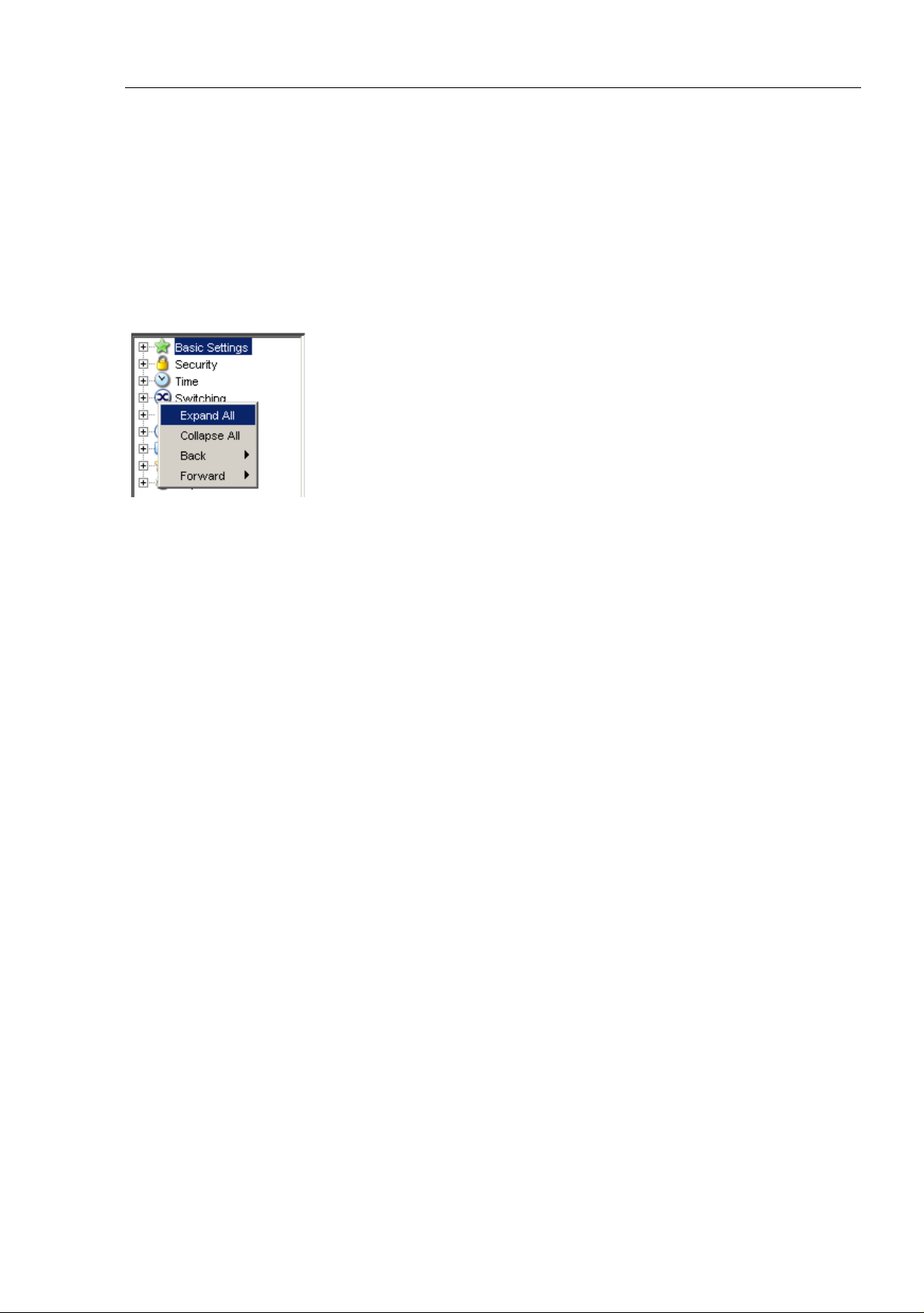
The menu section displays the menu items. By placing the mouse pointer in
the menu section and clicking the alternate mouse button you can use “Back”
to return to a menu item you have already selected, or “Forward” to jump to
a menu item you have already selected.
RM Web L2B
Release 5.3 05/2012
15
Page 16

Opening the Web-based Interface
16
RM Web L2B
Release 5.3 05/2012
Page 17

Basic Settings
1 Basic Settings
The Basic Settings menu contains the dialogs, displays and tables for the
basic configuration:
System
Network
Software
Port configuration
Power over Ethernet (PoE)
Load/Save
Restart
RM Web L2B
Release 5.3 05/2012
17
Page 18
Basic Settings
1.1 System
1.1 System
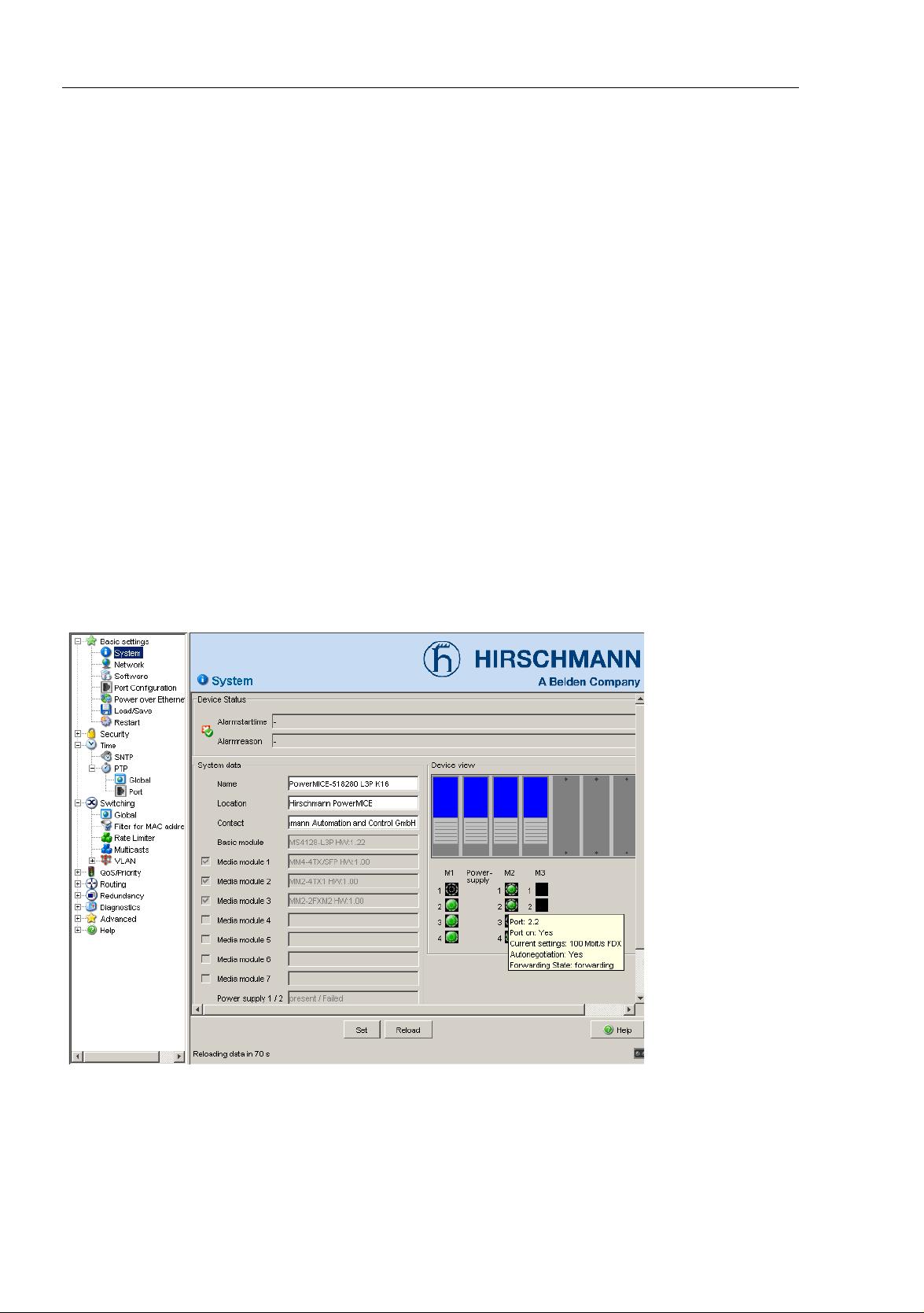
The “System“ submenu in the basic settings menu is structured as follows:
Device Status
System data
Device view
Reloading data
Figure 4: "System" Submenu
Device state
This section of the user interface (Web-based Interface) provides
information on the device status and the alarm states the device has
detected.
18
Release 5.3 05/2012
RM Web L2B
Page 19
Basic Settings
132
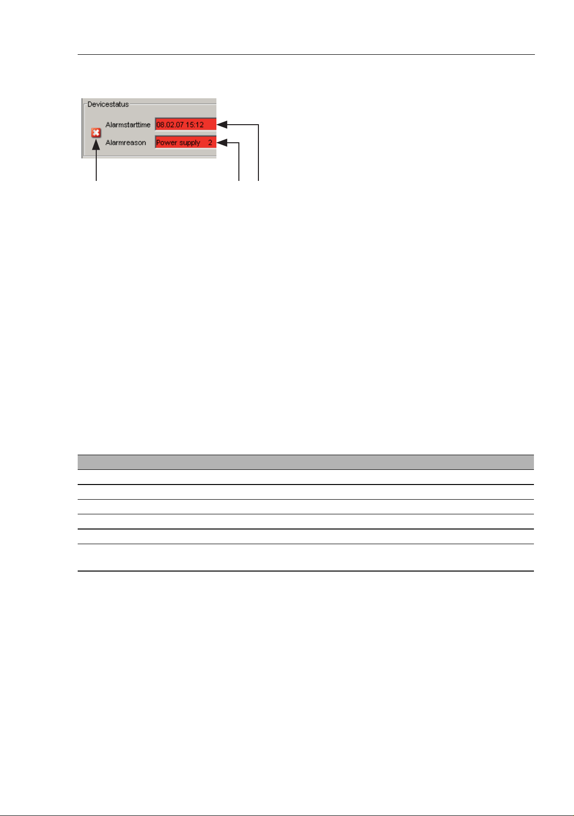
Figure 5: Device status and display of detected alarms
1 - Symbol indicates the Device Status
2 - Cause of the oldest existing alarm detected
3 - Time of the oldest existing alarm detected
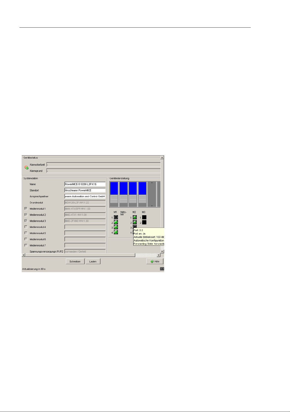
1.1 System
System Data
This area of the graphical user interface displays the system parameters
of the device. In the fields with a white background, you have the option
of changing the settings.
– the system name,
– the location description,
– the name of the contact person for this device,
Name Meaning
Name System name of this device
Location Location of this device
Contact The contact for this device
Basic module Hardware version of the device
Power supply (P1/P2) Status of power units (P1/P2)
Uptime Shows the time that has elapsed since this device was last
restarted.
Table 1: System Data
Device View
The device view shows the device with the current configuration. The
status of the individual ports is indicated by one of the symbols listed
below. You will get a full description of the port's status by positioning the
mouse pointer over the port's symbol.
RM Web L2B
Release 5.3 05/2012
19
Page 20

Basic Settings
Figure 6: Device View
1.1 System
What the symbols mean:
The port (10, 100 Mbit/s, 1, 10 Gbit/s) is enabled
and connection is OK.
The port is blocked by network management
and has no connection.
The port is blocked by network management
and has no connection.
The port is in auto-negotiation mode.
The port is in HDX mode.
The port (100 Mbit/s) is in the discard mode of a redundancyprotocol,
for example Spanning Tree or HIPER-Ring.
The port is in routing mode (100 Mbit/s).
20
RM Web L2B
Release 5.3 05/2012
Page 21

Basic Settings
1.1 System
Reloading
This area of the graphical user interface at the bottom left displays the
countdown time until the applet requests the current data of this dialog
again. Clicking the “Reload” button immediately calls up the current data
for the dialog. The applet polls the current data of the device automatically
every 100 seconds.
Figure 7: Time to next Reload
RM Web L2B
Release 5.3 05/2012
21
Page 22

Basic Settings
1.2 Network
1.2 Network
With the Basic settings:Network dialog you define the source from
which the device gets its IP parameters after starting, and you assign the IP
parameters and configure the HiDiscovery access.
22
RM Web L2B
Release 5.3 05/2012
Page 23
Basic Settings
1.2 Network
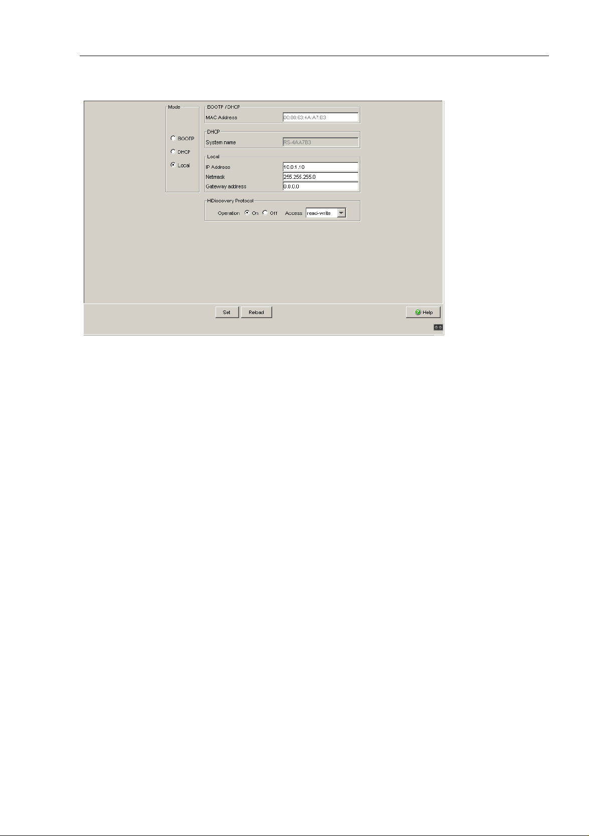
Figure 8: Network parameters dialog
Under “Mode”, you enter where the device gets its IP parameters:
In the BOOTP mode, the configuration is via a BOOTP or DHCP
server on the basis of the MAC address of the device (see on page 33
“Loading/Saving the Configuration”).
In the DHCP mode, the configuration is via a DHCP server on the
basis of the MAC address or the name of the device (see on page 33
“Loading/Saving the Configuration”).
In the local mode the net parameters in the device memory are used.
Enter the parameters on the right according to the selected mode.
You enter the name applicable to the DHCP protocol in the “Name” line in
the system dialog of the Web-based interface.
The HiDiscovery protocol allows you to allocate an IP address to the
device on the basis of its MAC address. Activate the HiDiscovery protocol
if you want to allocate an IP address to the device from your PC with the
enclosed HiDiscovery software (state on delivery: operation “on”, access
“read-write”).
RM Web L2B
Release 5.3 05/2012
23
Page 24

Basic Settings
1.2 Network
Note: When you change the network mode from ”Local“ to ”BOOTP“ or
”DHCP“, the server will assign a new IP address to the device. If the server
does not respond, the IP address will be set to 0.0.0.0, and the BOOTP/
DHCP process will try to obtain an IP address again.
24
RM Web L2B
Release 5.3 05/2012
Page 25
Basic Settings
1.3 Software
1.3 Software
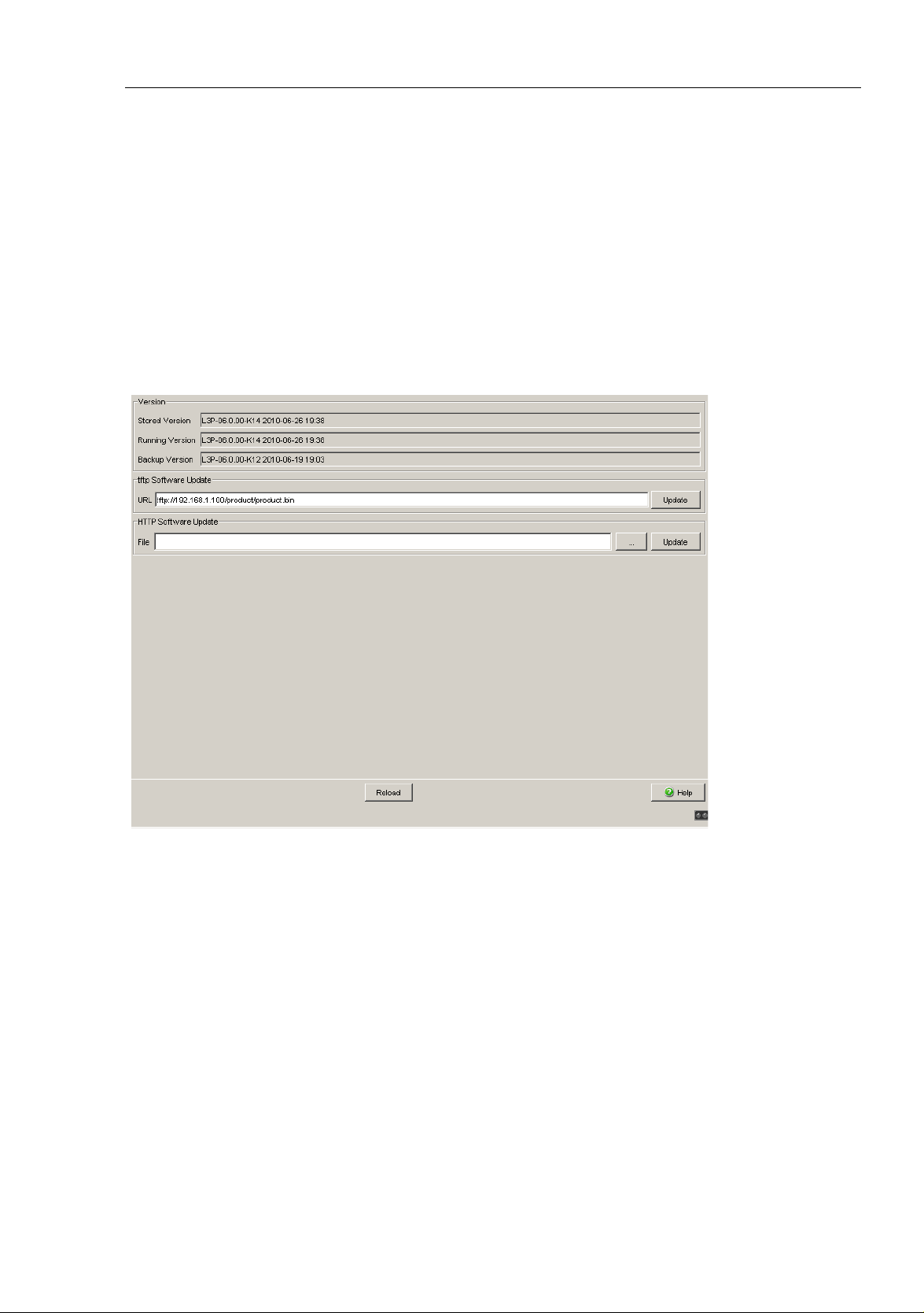
The software dialog enables you display the software versions in the device
and to carry out a software update of the device via file selection.
Figure 9: Software dialog
RM Web L2B
Release 5.3 05/2012
25
Page 26

Basic Settings
1.3.1 View the software versions present on the device
The dialog shows the existing software versions:
Stored Version:
The version of the software stored in the flash memory.
Running Version:
The version of the software currently running.
Backup Version:
The version of the previous software stored in the flash memory.
1.3 Software
1.3.2 TFTP Software Update
For a tftp update you need a tftp server on which the software to be loaded
is stored.
The URL identifies the path to the software stored on the tftp server. The URL
is in the format
tftp://IP address of the tftp server/path name/file name
(e.g. tftp://192.168.1.1/device/device.bin).
Click "tftp Update" to load the software from the tftp server to the device.
To start the new software after loading, cold start the device (see on page 38
“Restart”).
26
RM Web L2B
Release 5.3 05/2012
Page 27

Basic Settings
1.3 Software
1.3.3 HTTP Software Update
For an HTTP software update (via a file selection window), copy the device
software to a data carrier that you can access from your workstation.
In the file selection frame, click on “...”.
In the file selection window, select the device software (name type: *.bin,
e.g. device.bin) and click on “Open”.
Click on “Update” to transfer the software to the device.
The end of the update is indicated by one of the following messages:
Update finished.
Update aborted. Reason: incorrect file.
Update aborted. Reason: saving unsuccessful.
File not found (reason: file name not found or does not exist).
Unsuccessful Connection (reason: path without file name).
After the update is completed successfully, you activate the new software:
Select the Basic settings: Restart dialog and perform a cold start.
In a cold start, the device reloads the software from the non-volatile
memory, restarts, and performs a self-test.
In your browser, click on “Reload” so that you can access the device again
after it is booted.
RM Web L2B
Release 5.3 05/2012
27
Page 28

Basic Settings
1.4 Port Configuration
1.4 Port Configuration
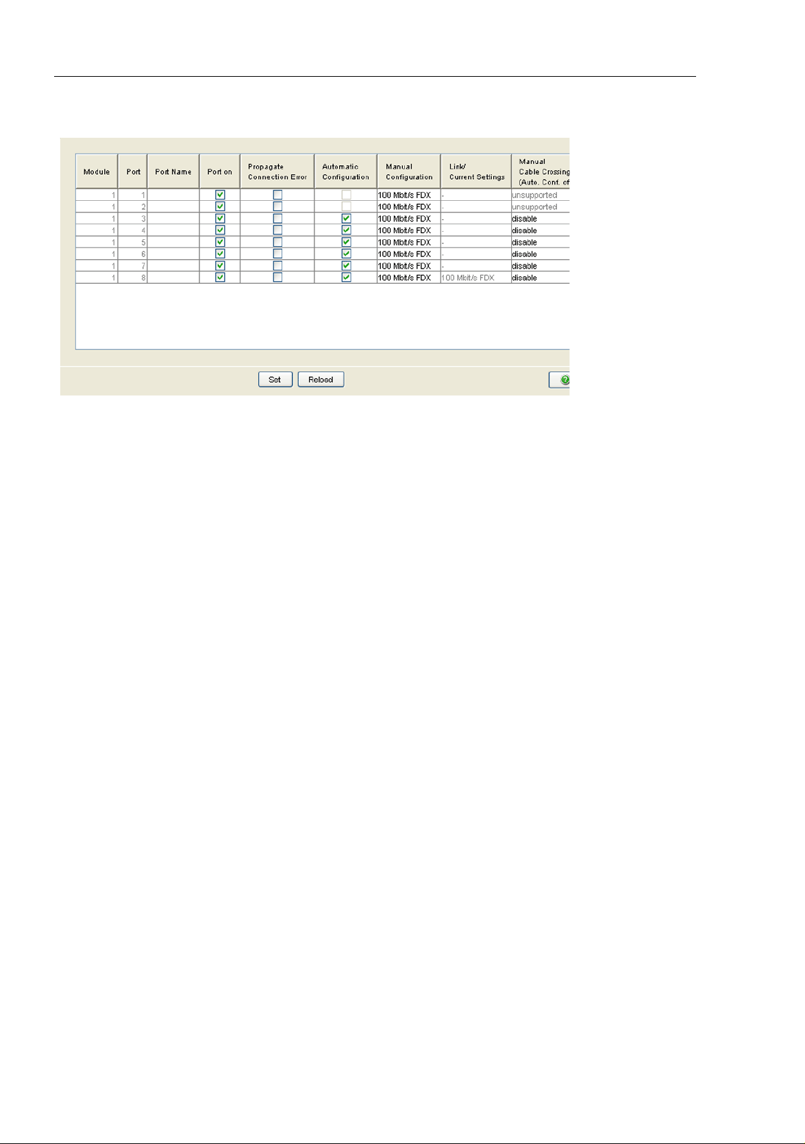
This configuration table allows you to configure each port of the device and
also display each port‘s current mode of operation (link state, bit rate (speed)
and duplex mode).
In the “Name” column, you can enter a name for every port.
In the “Ports on” column, you can switch on the port by selecting it here.
In the “Propagate connection error” column, you can specify that a link
alarm will be forwarded to the device status and/or the the signal contact
is to be opened.
In the “Automatic Configuration” column, you can activate the automatic
selection of the the operating mode (Autonegotiation) and the automatic
assigning of the connections (Auto cable crossing) of a TP port by
selecting the appropriate field. After the autonegotiation has been
switched on, it takes a few seconds for the operating mode to be set.
In the “Manual Configuration” column, you can set the operating mode for
this port. The choice of operating modes depends on the media module.
The possible operating modes are:
– 10 Mbit/s half duplex (HDX)
– 10 Mbit/s full duplex (FDX)
– 100 Mbit/s half duplex (HDX)
– 100 Mbit/s full duplex (FDX)
– 1000 Mbit/s half duplex (HDX)
– 1000 Mbit/s full duplex (FDX)
– 10 Gbit/s full duplex (FDX)
The “Link/Current Operating Mode” column displays the current operating
mode and thereby also an existing connection.
In the “Cable Crossing (Auto. Conf. off)” column, you assign the
connections of a TP port, if “Automatic Configuration” is deactivated for
this port. The possible settings are:
– enable: the device swaps the send and receive line pairs of the
TP cable for this port (MDIX).
– disable: the device does not swap the send and receive line pairs of
the TP cable for this port (MDI).
– unsupported: the port does not support this function (optical port).
28
RM Web L2B
Release 5.3 05/2012
Page 29

Basic Settings
1.4 Port Configuration
Note: The active automatic configuration has priority over the manual
configuration.
Note: The following settings are required for the ring ports in a HIPER-Ring:
Port type Bit rate Autonegotiation
(automatic
configuration)
TX 100 Mbit/s off on 100 Mbit/s full duplex (FDX)
Optical 100 Mbit/s off on 100 Mbit/s full duplex (FDX)
Table 2: Port settings for ring ports
Port setting Duplex
When you switch the DIP switch for the ring ports, the device sets the
required settings for the ring ports in the configuration table. The port, which
has been switched from a ring port to a normal port, is given the settings
Autonegotiation (automatic configuration) on and Port on. The settings
remain changeable for all ports.
RM Web L2B
Release 5.3 05/2012
29
Page 30
Basic Settings
1.4 Port Configuration
Figure 10: Port Configuration Table Dialog
30
RM Web L2B
Release 5.3 05/2012
Page 31

Basic Settings
1.5 Power over ETHERNET
1.5 Power over ETHERNET
For the devices
OS24-080900T5T5TFFBHH
OS24-080900T5T5TNEBHH
The device supports Power over ETHERNET according to IEEE 802.3at
(PoE+) and allows you to supply current to devices such as IP phones via the
twisted-pair cable.
On delivery, the Power over ETHERNET function is activated globally and on
all PoE-capable ports.
The device provides a nominal power of 61.1 W for the sum of all PoE ports.
Should the connected devices require more PoE power than is provided, the
device then switches PoE off at the ports. The device first switches PoE off
at the ports with the higher port number.
With “Function on/off” you turn the PoE on or off.
With “Send Trap” you can get the device to send a trap in the following
cases:
– If a value exceeds/falls below the performance threshold.
– If the PoE supply voltage is switched on/off at at least one port.
Enter the power threshold in “Threshold”. When this value is exceeded/
not achieved, the device will send a trap, provided that “Send trap” is
enabled. For the power threshold you enter the power yielded as a
percentage of the nominal power.
“Nominal Power” displays the power that the device nominally provides
for all PoE ports together.
“Reserved Power” displays the maximum power that the device provides
to all the connected PoE devices together on the basis of their
classification.
“Delivered Power” shows how large the current power requirement is at
all PoE ports.
The difference between the "nominal" and "reserved" power indicates how
much power is still available to the free PoE+ ports.
In the “POE on” column, you can enable/disable PoE at this port.
The “Status” column indicates the PoE status of the port.
RM Web L2B
Release 5.3 05/2012
31
Page 32

Basic Settings
1.5 Power over ETHERNET
The "Class" column indicates the class of the connected device:
Class: Maximum delivered power
0: 15.4 W
1: 4.0 W
2: 7.0 W
3: 15.4 W
4: 30.0 W
The column „Consumption [W]“ displays the current power delivered at
the respective port.
The “Name” column indicates the name of the port, see
Basic settings:Port configuration.
Figure 11: Power over Ethernet dialog
32
RM Web L2B
Release 5.3 05/2012
Page 33

Basic Settings
1.6 Loading/Saving the Configuration
1.6 Loading/Saving the
Configuration
With this dialog you can:
load a configuration,
save a configuration,
enter a URL,
restore the delivery configuration,
cancel a configuration change.
Figure 12: Load/Save dialog
RM Web L2B
Release 5.3 05/2012
33
Page 34

Basic Settings
1.6 Loading/Saving the Configuration
1.6.1 Loading a Configuration
In the “Load” frame, you have the option to
load a configuration saved on the device,
load a configuration stored under the specified URL,
load a configuration stored on the specified URL and save it on the
device,
load a configuration saved on the PC in binary format.
If you change the current configuration (for example, by switching a port off),
the Web-based interface changes the “load/save” symbol in the navigation
tree from a disk symbol to a yellow triangle. After saving the configuration,
the Web-based interface displays the “load/save” symbol as a disk again.
1.6.2 Saving the Configuration
In the “Save” frame, you have the option to
save the current configuration on the device,
save the current configuration in binary form in a file under the specified
URL,
save the current configuration in binary form on the PC,
Note: The loading process started by DHCP/BOOTP (see “Network” on
page 22) shows the selection of “from URL & save local” in the “Load” frame.
If you get an error message when saving a configuration, this could be due
to an active loading process. DHCP/BOOTP only finishes a loading process
when a valid configuration has been loaded. If DHCP/BOOTP does not find
a valid configuration, finish the loading process by loading the local
configuration from the device in the “Load” frame.
34
RM Web L2B
Release 5.3 05/2012
Page 35

Basic Settings
1.6 Loading/Saving the Configuration
If you change the current configuration (for example, by switching a port off),
the Web-based interface changes the “load/save” symbol in the navigation
tree from a disk symbol to a yellow triangle. After saving the configuration,
the Web-based interface displays the “load/save” symbol as a disk again.
1.6.3 URL
The URL identifies the path to the tftp server on which the configuration file
is to be stored. The URL is in the format: tftp://IP address of the tftp server/
path name/file name (e.g. tftp://192.168.1.100/device/
config.dat).
Note: The configuration file includes all configuration data, including the
passwords for accessing the device. Therefore, pay attention to the access
rights on the tftp server.
1.6.4 Deleting a configuration
In the "Delete" frame, you have the option to
Reset the current configuration to the state on delivery. The configuration
saved on the device is retained.
Reset the device to the state on delivery. In this case, the device deletes
its configuration in the volatile memory as well as in the non-volatile
memory. This includes the IP address. The device will be reachable again
over the network after it has obtained a new IP address, e.g., via DHCP
or the V.24 interface.
RM Web L2B
Release 5.3 05/2012
35
Page 36

Basic Settings
1.6 Loading/Saving the Configuration
1.6.5 Using the AutoConfiguration Adapter (ACA)
The ACAs are devices for loading/saving the configuration data of a device.
An ACA enables the configuration data to be transferred easily by means of
a substitute device of the same type.
Note: The described devices use the following AutoConfiguration Adapter:
ACA 11.
Storing the current configuration data in the ACA:
You have the option of transferring the current device configuration,
including the SNMP password, to the ACA and the flash memory by using
the “to device” option in the “Save” frame .
You have the option of transferring the current device configuration,
including the SNMP password, to the ACA and the flash memory by using
the “to device” option in the “Save” frame .
Transferring the configuration data from the ACA:
When you restart with the ACA connected, the device adopts the
configuration data of the ACA and saves it permanently in the flash
memory. If the connected ACA does not contain any valid data, for
example, if the delivery state is unchanged, the device loads the data from
the flash memory.
Note: Before loading the configuration data from the ACA, the device
compares the password in the device with the password in the ACA
configuration data.
The device loads the configuration data if
the admin password matches or
there is no password saved locally or
the local password is the original default password or
no configuration is saved locally.
36
RM Web L2B
Release 5.3 05/2012
Page 37

Basic Settings
Status Meaning
notPresent No ACA present
ok The configuration data from the ACA and the device match.
removed The ACA was removed after booting.
notInSync - The configuration data of the ACA and the device do not
match, or only one file exists
or
- no configuration file is present on the ACA or on the device
outOfMemory The local configuration data is too extensive to be stored on
the ACA.
wrongMachine The configuration data in the ACA originates from a different
device type and cannot be read or converted.
checksumErr The configuration data is damaged.
1.6 Loading/Saving the Configuration
a
,
b
Table 3: ACA status
.
a
In these cases, the ACA status is identical to the status “ACA not in
sync”, which sends “Not OK” to the signal contacts and the device status.,
b
In this case, the ACA status (“notInSync”) deviates from the status “ACA
not in sync”, which sends “OK” to the signal contacts, and the device
status.
RM Web L2B
Release 5.3 05/2012
37
Page 38

Basic Settings
1.7 Restart
1.7 Restart
This dialog provides you with the following functions:
initiate a cold start of the device. The device reloads the software from the
non-volatile memory, restarts, and performs a self-test.
Reload the website in your browser to reaccess the device after
restarting.
initiate a warm start of the device. In this case the device checks the
software in the volatile memory and restarts. If a warm start is not
possible, the device automatically performs a cold start.
reset the entries with the status “learned” in the filter table (MAC address
table).
reset the ARP table.
The device maintains an ARP table internally.
If, for example, you assign a new IP address to a computer and
subsequently cannot set up a connection to the device, you then reset the
ARP table.
reset the port counters.
delete the log file.
Note: During the restart, the device temporarily does not transfer any data,
and it cannot be accessed via the Web-based interface or other management
systems such as Industrial HiVision.
RM Web L2B
38
Release 5.3 05/2012
Page 39

Basic Settings
1.7 Restart
Figure 13: Restart Dialog
RM Web L2B
Release 5.3 05/2012
39
Page 40

Basic Settings
1.7 Restart
40
RM Web L2B
Release 5.3 05/2012
Page 41

Security
2 Security
The “Security” menu contains the dialogs, displays and tables for configuring
the security settings:
Password/SNMPv3 access
SNMPv1/v2 access
Web access
RM Web L2B
Release 5.3 05/2012
41
Page 42

Security
2.1 Password / SNMPv3 access
2.1 Password / SNMPv3 access
This dialog gives you the option of changing the read and read/write
passwords for access to the device via the Web-based interface, via the CLI,
and via SNMPv3 (SNMP version 3).
Set different passwords for the read password and the read/write password
so that a user that only has read access (user name “user”) does not know,
or cannot guess, the password for read/write access (user name “admin”).
If you set identical passwords, when you attempt to write this data the device
reports a general error.
The Web-based interface and the user interface (CLI) use the same
passwords as SNMPv3 for the users “admin” and “user”.
Note: Passwords are case-sensitive.
Select “Modify read-only password (user)” to enter the read password.
Enter the new read password in the “New password” line and repeat your
entry in the “Please retype” line.
Select “Modify read-write password (admin)” to enter the read/write
password.
Enter the read/write password and repeat your entry.
42
RM Web L2B
Release 5.3 05/2012
Page 43

Security
2.1 Password / SNMPv3 access
Figure 14: Dialog Password/SNMP Access
Note: If you do not know a password with “read/write” access, you will not
have write access to the device.
Note: For security reasons, the device does not display the passwords.
Make a note of every change. You cannot access the device without a valid
password.
Note: For security reasons, SNMPv3 encrypts the password. With the
“SNMPv1” or “SNMPv2” setting in the dialog Security:SNMPv1/v2
access, the device transfers the password unencrypted, so that this can
also be read.
Note: Use between 5 and 32 characters for the password in SNMPv3, since
many applications do not accept shorter passwords.
RM Web L2B
Release 5.3 05/2012
43
Page 44

Security
2.1 Password / SNMPv3 access
You can block access via a Web browser in a separate dialog (see on
page 48 “Web Access”).
Access at IP address level is restricted in a separate dialog (see on page 45
“SNMPv1/v2 Access Settings”).
44
RM Web L2B
Release 5.3 05/2012
Page 45

Security
2.2 SNMPv1/v2 Access Settings
2.2 SNMPv1/v2 Access Settings
With this dialog you can select access via SNMPv1 or SNMPv2. In the state
on delivery, both protocols are activated.
You can thus manage the device with HiVision and communicate with earlier
versions of SNMP.
Note: To be able to read and/or change the data in this dialog, log in to the
Web-based interface with the user name “admin” and the relevant password.
In the “Index” column, the device displays the access restriction‘s
sequential number.
In the “Password” column, you enter the password with which a
management station may access the device via SNMPv1/v2 from the
specified address range.
Note: Passwords are case-sensitive.
In the “IP Address” column, you enter the IP address which may access
the device. No entry in this field, or the entry “0.0.0.0”, allows access to
this device from computers with any IP address. In this case, the only
access protection is the password.
In the “IP Mask” column, much the same as with netmasks, you have the
option of selecting a group of IP addresses.
Example:
255.255.255.255: a single IP address
255.255.255.240 with IP address = 172.168.23.20:
the IP addresses 172.168.23.16 to 172.168.23.31.
RM Web L2B
Release 5.3 05/2012
45
Page 46

Security
Binary notation of the mask 255.255.255.240:
1111 1111 1111 1111 1111 1111 1111 0000
mask bits
Binary notation of the IP address 172.168.23.20:
1010 1100 1010 1000 0001 0111 0001 0100
The binary representation of the mask with the IP address yields
an address range of:
1010 1100 1010 1000 0001 0111 0001 0000 bis
1010 1100 1010 1000 0001 0111 0001 1111
i.e.: 172.168.23.16 to 172.168.23.31
2.2 SNMPv1/v2 Access Settings
In the “Access Mode” column, you specify whether this computer can
access the device with the read password (access mode “readOnly”) or
with the read/write password (access mode “readWrite”).
Note: The password for the “readOnly” access mode is the same as the
SNMPv3 password for read access.
The password for the “readWrite” access mode is the same as the
SNMPv3 password for read/write access.
If you are changing one of the passwords, manually set the corresponding
password for SNMPv3 to the same value (see on page 42 “Password /
SNMPv3 access”). This way you ensure that you can also access with the
same password via SNMPv3.
You can activate/deactivate this table entry in the “Active” column.
Note: If you have not activated any row, the device does not apply any
access restriction with regard to the IP addresses.
With “Create entry” you create a new row in the table.
With “Delete entry” you delete selected rows in the table.
Note: The device prevents deleting or changing the row with the password
currently in use.
46
RM Web L2B
Release 5.3 05/2012
Page 47

Security
2.2 SNMPv1/v2 Access Settings
Figure 15: SNMPv1/v2 Access Dialog
RM Web L2B
Release 5.3 05/2012
47
Page 48

Security
2.3 Web Access
2.3 Web Access
This dialog allows you to switch off the Web server on the device.
Figure 16: Web Access dialog
2.3.1 Description of Web Access (http)
The device's Web server allows you to configure the device by using the
Web-based interface. You can deactivate the Web server to prevent Web
access to the device.
The server is activated in its state on delivery.
48
RM Web L2B
Release 5.3 05/2012
Page 49

Security
2.3 Web Access
After the Web server has been switched off, it is no longer possible to log in
via a Web browser. The login in the open browser window remains active.
Note: The Command Line Interface allows you to reactivate the Web server.
RM Web L2B
Release 5.3 05/2012
49
Page 50

Security
2.3 Web Access
50
RM Web L2B
Release 5.3 05/2012
Page 51

Time
3Time
With this dialog you can enter time-related settings independently of the time
synchronization protocol selected.
The “System Time (UTC)” displays the time with reference to Universal
Time Coordinated.
The time displayed is the same worldwide. Local time differences are not
taken into account.
The ”system time” uses "System Time (UTC)", allowing for the local time
difference from "System Time (UTC)".
“System time” = “System Time (UTC)” + “local offset”.
“Time source” displays the source of the following time data. The device
automatically selects the source with the greatest accuracy.
Possible sources are: local, ptp and sntp. The source is initially
local.
If PTP is activated and the device receives a valid PTP frame, it sets its
time source to ptp. If SNTP is activated and if the device receives a valid
SNTP packet, the device sets its time source to sntp. The device gives
the PTP time source priority over SNTP
With “Set time from PC”, the device takes the PC time as the system time
and calculates the system time (UTC) using the local time difference.
“System Time (UTC)” = “system time” - “local offset”
The “local offset” is for displaying/entering the time difference between the
local time and the “System Time (UTC)”.
With ”Set offset from PC“, the device determines the time zone on your
PC and uses it to calculate the local time difference.
Note: When setting the time in zones with summer and winter times, make
an adjustment for the local offset, if applicable. The device can also get the
SNTP server IP address and the local offset from a DHCP server.
RM Web L2B
Release 5.3 05/2012
51
Page 52

Time
Interaction of PTP and SNTP
According to PTP (IEEE 1588) and SNTP, both protocols can exist in parallel
in the same network. However, since both protocols affect the system time of
the device, situations may occur in which the two protocols compete with
each other.
The PTP reference clock gets its time either via SNTP or from its own clock.
All other clocks favor the PTP time as the source.
Figure 17: Time Dialog:Basic Settings
52
RM Web L2B
Release 5.3 05/2012
Page 53

Time
3.1 SNTP configuration
3.1 SNTP configuration
The Simple Network Time Protocol (SNTP) enables you to synchronize the
system time in your network.
The device supports the SNTP client and the SNTP server function.
The SNTP server makes the UTC (Universal Time Coordinated) available.
UTC is the time relating to the coordinated world time measurement. The
time displayed is the same worldwide. Local time differences are not taken
into account.
SNTP uses the same packet format as NTP. In this way, an SNTP client can
receive the time from an SNTP server as well as from an NTP server.
Note: For accurate system time distribution with cascaded SNTP servers
and clients, use only network components (routers, switches, hubs) in the
signal path between the SNTP server and the SNTP client which forward
SNTP packets with a minimized delay.
Parameter Meaning
Function Switch the SNTP function on and off
In this frame you switch the SNTP function on/off.
When it is switched off, the SNTP server does not send any SNTP
packets or respond to any SNTP requests.
The SNTP client does not send any SNTP requests or evaluate any
SNTP Broadcast/Multicast packets.
Table 4: Configuration SNTP Client and Server
Parameter Meaning Possible Values Default Setting
SNTP Status Displays conditions such as “Server
cannot be reached”.
--
Table 5: SNTP Status
RM Web L2B
Release 5.3 05/2012
53
Page 54

Time
3.1 SNTP configuration
Parameter Meaning Possible
Values
Server status Switches the SNTP server On/Off. On, Off On
Anycast destination
address
Anycast send interval Time interval at which the device sends
Disable server at local
time source
IP address, to which the SNTP server of the
device sends the SNTP packets (see
table 7).
SNTP packets.
Enables/disables the SNTP server function if
the status of the time source is local (see
Time Dialog).
Valid IPv4
address
1 - 3.600 120
On, Off Off
Default
Setting
0.0.0.0
Table 6: SNTP Server Configuration
IP destination
address
0.0.0.0 Nobody
Unicast Unicast
224.0.1.1 Multicast
255.255.255.255 Broadcast
Send SNTP packets
periodically to
Table 7: Periodic sending of SNTP packets
54
RM Web L2B
Release 5.3 05/2012
Page 55

Time
Parameter Meaning Possible Values Default
Client Status Switches the SNTP client On/Off. On, Off On
External server
address
Redundant
server address
Server Request
Interval
Accept SNTP
Broadcasts
Threshold for
obtaining the
UTC [ms]
Disable client
after successful
synchronization
IP address of the SNTP server from which the
device periodically requests the system time.
IP address of the SNTP server from which the
device periodically requests the system time if
it does not receive a response to a request
from the “External server address” within 0.5
seconds.
Time interval at which the device requests
SNTP packets
Specifies whether the device accepts the
system time from SNTP Broadcast/Multicast
packets that it receives.
The device changes the time as soon as the
deviation from the server time is above this
threshold in milliseconds. This reduces the
frequency of time changes.
Enable/disable further time synchronizations
once the client, after its activation, has
synchronized its time with the server.
3.1 SNTP configuration
Setting
Valid IPv4 address 0.0.0.0
Valid IPv4 address 0.0.0.0
1 s - 3,600 s 30 s
On, Off On
0 - 2.147.483.647
31
(2
-1)
On, Off Off
0
Table 8: SNTP Client Configuration
Note: If you have enabled PTP at the same time, the SNTP client first
collects 60 time stamps before it deactivates itself. The device thus
determines the drift compensation for its PTP clock. With the preset server
request interval, this takes about half an hour.
Note: If you are receiving the system time from an external/redundant server
address, switch off the reception of SNTP Broadcasts (see “Accept SNTP
Broadcasts”). You thus ensure that the device only takes the time from a
defined SNTP server.
RM Web L2B
Release 5.3 05/2012
55
Page 56

Time
3.1 SNTP configuration
Figure 18: SNTP Dialog
56
RM Web L2B
Release 5.3 05/2012
Page 57

Time
3.2 PTP (IEEE 1588)
3.2 PTP (IEEE 1588)
Precise time management is required for running time-critical applications via
a LAN.
The IEEE 1588 standard with the Precision Time Protocol (PTP) describes a
procedure that determines the best master clock in a LAN and thus enables
precise synchronization of the clocks in this LAN.
Devices without PTP hardware support, which only have ports absent a
time stamp unit, support the PTP simple mode. This mode gives a less
accurate division of time.
With these devices
enable/disable the PTP function in the PTP Dialog,
select PTP mode in the PTP Dialog.
–Select v1-simple-mode if the reference clock uses PTP Version 1.
–Select v2-simple-mode, if the reference clock uses PTP Version 2.
Note: In the simple mode a device synchronizes itself with PTP messages
received. This mode provides a precision comparable to SNTP absent other
functions, such as PTP management or runtime measuring.
If you want to transport PTP time accurately through your network, only use
devices with PTP hardware support on the transport paths.
RM Web L2B
Release 5.3 05/2012
57
Page 58

Time
3.2 PTP (IEEE 1588)
Figure 19: Dialog PTP
58
RM Web L2B
Release 5.3 05/2012
Page 59

Switching
4 Switching
The switching menu contains the dialogs, displays and tables for configuring
the switching settings:
Switching Global
Filters for MAC Addresses
Rate Limiter
Multicasts
RM Web L2B
Release 5.3 05/2012
59
Page 60

Switching
4.1 Switching Global
4.1 Switching Global
Variable Meaning Possible Values Default Setting
MAC address
(read only)
Aging Time (s) Enter the Aging Time in seconds for
Table 9: Switching:Global dialog
Display the MAC address of the device
15-3.825 30
dynamic MAC address entries.
Figure 20: Dialog Switching Global
60
RM Web L2B
Release 5.3 05/2012
Page 61

Switching
4.2 Filters for MAC addresses
4.2 Filters for MAC addresses
The filter table for MAC addresses is used to display and edit filters. Each row
represents one filter. Filters specify the way in which data packets are sent.
They are set automatically by the device (learned status) or manually. Data
packets whose destination address is entered in the table are sent from the
receiving port to the ports marked in the table. Data packets whose
destination address is not in the table are sent from the receiving port to all
other ports. The following conditions are possible:
learned: The filter was created automatically by the device.
invalid: With this status you delete a manually created filter.
permanent: The filter is stored permanently in the device or on the URL
(see on page 33 “Loading/Saving the Configuration”).
igmp: The filter was created by IGMP Snooping.
In the “Create” dialog (see buttons below), you can create new filters.
Figure 21: Filter Table dialog
RM Web L2B
Release 5.3 05/2012
61
Page 62

Switching
4.2 Filters for MAC addresses
Note: The filter table allows you to create up to 100 filter entries for Multicast
addresses.
62
RM Web L2B
Release 5.3 05/2012
Page 63

Switching
4.3 Multicasts
With this dialog you can:
activate/deactivate the IGMP function globally,
configure the IGMP protocol globally and per port.
4.3 Multicasts
Figure 22: Multicasts dialog
RM Web L2B
Release 5.3 05/2012
63
Page 64

Switching
4.3 Multicasts
4.3.1 Global Configuration
In this frame you can:
activate/deactivate the IGMP Snooping protocol.
Parameter Meaning Default setting
IGMP Snooping Activate IGMP Snooping globally for the entire device. deselected
disabled Deactivate IGMP Snooping globally for the entire device.
If IGMP Snooping is switched off:
the device does not evaluate Query and Report
packets received, and
it sends (floods) received data packets with a
Multicast address as the destination address to all
ports.
selected
Table 10: Global setting
4.3.2 IGMP Querier and IGMP settings
With these frames you can enter global settings for the IGMP settings and
the IGMP Querier function.
Prerequisite: The IGMP Snooping function is activated globally.
64
RM Web L2B
Release 5.3 05/2012
Page 65

Switching
Parameter Bedeutung Wertebereich Voreinstellung
IGMP Querier
IGMP Querier
enabled
Protocol Version Select IGMP version 1, 2 or 3. 1, 2, 3 2
Send Interval Enter the interval at which the switch
IGMP settings
Current querier IP
address
Max. Response
Time
Group Membership
Interval
Switch query function on/off on
off
2-3,599 s
sends query packets.
All IGMP-capable terminal devices
respond to a query with a report
message.
Display the IP address of the router/
switch that has the query function.
Zeit eingeben, innerhalb derer die
Multicast-Gruppen-Mitglieder auf ein
Query antworten sollen.
Die Multicast-Gruppen-Mitglieder
wählen einen zufälligen Wert innerhalb
der Response Time für ihre Antwort
aus, um zu verhindern, dass alle
Multicast-Gruppen-Mitglieder
gleichzeitig auf den Query antworten.
Enter the period for which a dynamic
Multicast group remains entered in the
device if it does not receive any report
messages.
Protokoll
Version
- 1, 2: 1-25 s
- 3: 1-3.598 s
3-3,600 s
a
a
4.3 Multicasts
off
125 s
10 s
a
260 s
Table 11: IGMP Querier and IGMP settings
a. Beachten Sie den Parameter-Zusammenhang zwischen Max.-Response-Time, Sende-
Intervall und Group-Membership-Intervall (see table 12.)
The parameters
– Max. Response Time,
– Send Interval and
– Group Membership Interval
have a relationship to one another:
Max. Response Time < Send Interval < Group Membership Interval.
If you enter values that contradict this relationship, the device then replaces
these values with a default value or with the last valid values.
RM Web L2B
Release 5.3 05/2012
65
Page 66

Switching
4.3 Multicasts
Parameter Protocol
Version
Max. Response Time, 1, 2
3
Send Interval 1, 2, 3 2-3,599 seconds 125 seconds
Group Membership Interval 1, 2, 3 3-3,600 seconds 260 seconds
Table 12: Value range for
- Max. Response Time
- Send Interval
- Group Membership Interval
Value range Default setting
1-25 seconds
1-3,598 seconds
10 seconds
For “Send Interval” and “Max. Response Time”,
– select a large value if you want to reduce the load on your network and
can accept the resulting longer switching times,
– select a small value if you require short switching times and can accept
the resulting network load.
4.3.3 Multicasts
In this frame you specify how the device transmits packets with
unknown MAC/IP multicast addresses not learned with IGMP Snooping
known MAC/IP multicast addresses learned with IGMP Snooping.
Prerequisite: The IGMP Snooping function is activated globally.
66
RM Web L2B
Release 5.3 05/2012
Page 67

Switching
Parameter Meaning Value range Default setting
Unknown Multicasts
Send to Query Ports:
The device sends the packets
with an unknown MAC/IP
Multicast address to all query
ports.
Send to All Ports:
The device sends the packets
with an unknown MAC/IP
Multicast address to all ports.
Discard:
The device discards all packets
with an unknown MAC/IP
Multicast address.
Known Multicasts
Send to query and registered
ports:
The device sends the packets
with a known MAC/IP Multicast
address to all query ports and
to registered ports.
The advantage of this is that it
works in many applications
without any additional
configuration.
Application:
“Flood and Prune” routing in
PIM-DM.
Send to Query
Ports, Send to
All Ports,
Discard
Send to query
and registered
ports, send to
registered
ports
4.3 Multicasts
Send to All
Ports
Send to
registered ports
Send to registered ports:
The device sends the packets
with a known MAC/IP Multicast
address to registered ports.
The advantage of this setting is
that it uses the available
bandwidth optimally through
direct distribution. It requires
additional port settings.
Application:
Routing protocol PIM-SM.
Table 13: Known and unknown Multicasts
RM Web L2B
Release 5.3 05/2012
67
Page 68

Switching
4.3 Multicasts
Note: The way in which unlearned Multicast addresses are handled
also applies to the reserved addresses from the “Local Network Control
Block” (224.0.0.0 - 224.0.0.255). This can have an effect on higher-level
routing protocols.
68
RM Web L2B
Release 5.3 05/2012
Page 69

Switching
4.3 Multicasts
4.3.4 Settings per Port (Table)
With this configuration table you can enter port-related settings for:
IGMP
Parameter Meaning Value range Default setting
Module Module number for modular devices,
otherwise 1.
Port Module and port numbers to which this
entry applies.
IGMP on Switch IGMP on/off for each port.
Switching IGMP off at a port prevents
registration for this port.
Prerequisite: The IGMP Snooping
function is activated globally.
IGMP Forward All Switch the IGMP Snooping function
Forward All on/off.
With the IGMP Forward All setting,
the device sends to this port all data
packets with a Multicast address in the
destination address field.
Prerequisite: The IGMP Snooping
function is activated globally.
--
On
Off
On
Off
On
Off
Note: If a number of routers are
connected to a subnetwork, you must
use IGMP version 1 so that all the
routers receive all the IGMP reports.
Note: If you use IGMP version 1 in a
subnetwork, then you must also use
IGMP version 1 in the entire network.
IGMP Automatic
Query Port
Displays which ports the device has
learned as query ports if “automatic” is
selected in “Static Query Port”.
Prerequisite: In the
Switching:Multicasts:Global
Setting dialog, the IGMP Snooping
mode is selected.
Table 14: Settings per port
yes, no -
RM Web L2B
Release 5.3 05/2012
69
Page 70

Switching
Parameter Meaning Value range Default setting
Static Query Port The device sends IGMP report
messages to the ports at which it
receives IGMP queries (default
setting). This column allows you to also
send IGMP report messages to: other
selected ports (enable) or connected
Hirschmann devices (automatic).
Prerequisite: In the
Switching:Multicasts:Global
Setting dialog, the IGMP Snooping
mode is selected.
Learned Query
Port
Shows at which ports the device has
received IGMP queries if “disable” is
selected in “Static Query Port”.
Prerequisite: The IGMP Snooping
function is activated globally.
enable,
disable,
automatic
Yes
No
4.3 Multicasts
disable
-
Table 14: Settings per port
Note: If the device is incorporated into a HIPER-Ring, you can use the
following settings to quickly reconfigure the network for data packets with
registered Multicast destination addresses after the ring is switched:
Switch on the IGMP Snooping on the ring ports and globally, and
activate “IGMP Forward All” per port on the ring ports.
70
RM Web L2B
Release 5.3 05/2012
Page 71

QoS/Priority
5 QoS/Priority
The device enables you to set
how it evaluates the QoS/prioritizing information of incoming data
packets:
– VLAN priority based on IEEE 802.1Q/ 802.1D (Layer 2)
– Type of Service (ToS) or DiffServ (DSCP) for IP packets (Layer 3)
which QoS/prioritizing information it writes to outgoing data packets (e.g.
priority for management packets, port priority).
The QoS/Priority menu contains the dialogs, displays and tables for
configuring the QoS/priority settings:
Global
Port configuration
IEEE 802.1D/p mapping
IP DSCP mapping
RM Web L2B
Release 5.3 05/2012
71
Page 72

QoS/Priority
5.1 Global
5.1 Global
With this dialog you can:
enter the IP-DSCP value for management packets in the range 0 to 63
(default setting: 0 (be/cs0)).
In order for you to have full access to the management of the device, even
when there is a high network load, the device enables you to prioritize
management packets.
In prioritizing management packets (SNMP, Telnet, etc.), the device
sends the management packets with priority information.
Note the assignment of the IP-DSCP value to the traffic class (see
table 19).
Note: Certain DSCP values have DSCP names, such as be/cs0 to cs7
(class selector) or af11 to af43 (assured forwarding) and ef (expedited
forwarding).
72
RM Web L2B
Release 5.3 05/2012
Page 73

QoS/Priority
5.1 Global
display the maximum number of queues possible per port.
The device supports 4 (8 for MACH 4000, MACH 104, MACH 1040 and
PowerMICE) priority queues (traffic classes in compliance with IEEE
802.1D).
select the trust mode globally. You use this to specify how the device
handles received data packets that contain priority information.
“untrusted”
The device ignores the priority information in the packet and always
assigns the packets the port priority of the receiving port.
“trustDot1p”:
The device prioritizes received packets that contain VLAN tag
information according to this information (assigning them to a traffic
class - see “802.1D/p mapping”).
The device prioritizes received packets that do not contain any tag
information (assigning them to a traffic class - see “Entering the port
priority”) according to the port priority of the receiving port .
“trustIpDscp”:
The device prioritizes received IP packets (assigning them to a traffic
class - see “IP DSCP mapping”) according to their DSCP value.
The device prioritizes received packets that are not IP packets
(assigning them to a traffic class - see “Entering the port priority”)
according to the port priority of the receiving port .
Traffic class New VLAN priority
when receiving port
has an even port priority
00 1
12 3
24 5
36 7
Table 15: VLAN priority remarking
New VLAN priority
when receiving port
has an odd port priority
RM Web L2B
Release 5.3 05/2012
73
Page 74

QoS/Priority
5.1 Global
Figure 23: Global dialog
74
RM Web L2B
Release 5.3 05/2012
Page 75

QoS/Priority
5.2 Port Configuration
5.2 Port Configuration
This dialog allows you to configure the ports. You can:
assign a port priority to a port.
Parameter Meaning
Module Module of the device on which the port is located.
Port Port to which this entry applies.
Port priority Enter the port priority.
Table 16: Port configuration table
Figure 24: Port configuration dialog
RM Web L2B
Release 5.3 05/2012
75
Page 76

QoS/Priority
5.2 Port Configuration
5.2.1 Entering the port priority
Double-click a cell in the “Port priority” column and enter the priority (0-7).
According to the priority entered, the device assigns the data packets that
it receives at this port to a traffic class (see table 17).
Prerequisite:
Setting in the dialog Global: Trust Mode: untrusted(see on
page 72 “Global”) or
Setting in the dialog Global: Trust Mode: trustDot1p(see on
page 72 “Global”) and the data packets do not contain a VLAN tag or
Setting in the dialog Global: Trust Mode: trustIpDscp(see on
page 72 “Global”) and the data packets are not IP packets.
Port priority Traffic class (default setting) IEEE 802.1D traffic type
0 1 Best effort (default)
1 0 Background
2 0 Standard
3 1 Excellent effort (business critical)
4 2 Controlled load (streaming multimedia)
5 2 Video, < 100 ms of latency and jitter
6 3 Voice, < 10 ms of latency and jitter
7 3 Network control reserved traffic
Table 17: Assigning the port priority to the 4 traffic classes
76
RM Web L2B
Release 5.3 05/2012
Page 77

QoS/Priority
5.3 802.1D/p mapping
5.3 802.1D/p mapping
The 802.1D/p mapping dialog allows you to assign a traffic class to every
VLAN priority.
RM Web L2B
Release 5.3 05/2012
77
Page 78

QoS/Priority
5.3 802.1D/p mapping
Figure 25: 802.1D/p Mapping dialog
Enter the desired value from 0 to 3 in the Traffic Class field for every
VLAN priority.
Port priority Traffic class (default setting) IEEE 802.1D traffic type
0 1 Best effort (default)
1 0 Background
2 0 Standard
3 1 Excellent effort (business critical)
4 2 Controlled load (streaming multimedia)
5 2 Video, < 100 ms of latency and jitter
6 3 Voice, < 10 ms of latency and jitter
7 3 Network control reserved traffic
Table 18: Assigning the VLAN priority to the 4 traffic classes
78
RM Web L2B
Release 5.3 05/2012
Page 79

QoS/Priority
5.3 802.1D/p mapping
Note: Network protocols and redundancy mechanisms use the highest traffic
class 3. Therefore, select other traffic classes for application data.
RM Web L2B
Release 5.3 05/2012
79
Page 80

QoS/Priority
5.4 IP DSCP mapping
5.4 IP DSCP mapping
The IP DSCP mapping table allows you to assign a traffic class to every
DSCP value.
Enter the desired value from 0 to 3 in the Traffic Class field for every
DSCP value (0-63).
Figure 26: IP DSCP mapping table
The different DSCP values get the device to employ a different forwarding
behavior, namely Per-Hop Behavior (PHB).
PHB classes:
Class Selector (CS0-CS7): For reasons of compatibility to TOS/IP
Precedence
Expedited Forwarding (EF): Premium service.
Reduced delay, jitter + packet loss (RFC 2598)
RM Web L2B
80
Release 5.3 05/2012
Page 81

QoS/Priority
5.4 IP DSCP mapping
Assured Forwarding (AF): Provides a differentiated schema for handling
different data traffic (RFC 2597).
Default Forwarding/Best Effort: No particular prioritizing.
DSCP value DSCP name Traffic class
(default setting)
0 Best Effort /CS0 1
1-7 1
8CS10
9,11,13,15 0
10,12,14 AF11,AF12,AF13 0
16 CS2 0
17,19,21,23 0
18,20,22 AF21,AF22,AF23 0
24 CS3 1
25,27,29,31 1
26,28,30 AF31,AF32,AF33 1
32 CS4 2
33,35,37,39 2
34,36,38 AF41,AF42,AF43 2
40 CS5 2
41,42,43,44,45,47 2
46 EF 2
48 CS6 3
49-55 3
56 CS7 3
57-63 3
Table 19: Mapping the DSCP values onto the traffic classes
RM Web L2B
Release 5.3 05/2012
81
Page 82

QoS/Priority
5.4 IP DSCP mapping
82
RM Web L2B
Release 5.3 05/2012
Page 83

Redundancy
6 Redundancy
Under Redundancy you will find the dialogs and views for configuring and
monitoring the redundancy functions:
Ring Redundancy
Sub-Ring
Redundant coupling of Rings and network segments
Rapid Spanning Tree Protocol (RSTP)
RM Web L2B
Release 5.3 05/2012
83
Page 84

Redundancy
6.1 Ring Redundancy
6.1 Ring Redundancy
The concept of the Ring Redundancy enables the construction of highavailability, ring-shaped network structures.
If a section is down, the ring structure of a
HIPER-(HIGH PERFORMANCE REDUNDANCY) Ring with up to 50
devices typically transforms back to a line structure within 80 ms (possible
settings: standard/accelerated).
MRP (Media Redundancy Protocol) Ring (IEC 62439) of up to 50 devices
typically transforms back to a line structure within 80 ms (adjustable to
max. 200 ms/500 ms).
With the aid of a device's Ring Manager (RM) function you can close both
ends of a backbone in a line-type configuration to form a redundant ring.
Within a HIPER-Ring, you can use any combination of the following
devices:
– RS2-./.
– RS2-16M
–RS2-4R
– RS20, RS30, RS40
–RSB20
– RSR20, RSR30
– OCTOPUS
–MICE
–MS20, MS30
–PowerMICE
– MACH 100
– MACH 1000
– MACH 3000
– MACH 4000
Within an MRP-Ring, you can use devices that support the MRP protocol
based on IEC62439.
Depending on the device model, the Ring Redundancy dialog allows you to:
Select one of the available Ring Redundancy versions, or change it.
Display an overview of the current Ring Redundancy configuration.
Create new Ring Redundancies.
Configure existing Ring Redundancies.
Enable/disable the Ring Manager function.
RM Web L2B
84
Release 5.3 05/2012
Page 85

Redundancy
6.1 Ring Redundancy
Receive Ring information.
Delete the Ring Redundancy.
Note: Only one Ring Redundancy method can be enabled on one device at
any one time. When changing to another Ring Redundancy method,
deactivate the function for the time being.
Parameter Meaning
Version Select the Ring Redundancy version you want to use:
HIPER-Ring
MRP
Default setting is HIPER-Ring
Ring port No. In a ring, every device has 2 neighbors. Define 2 ports as ring ports to which the
neighboring devices are connected.
Module Module identifier of the ports used as ring ports
Port Port identifier of the ports used as ring ports
Operation Value depends on the Ring Redundancy version used. Described in the
following sections for the corresponding Ring Redundancy version.
Table 20: Ring Redundancy basic configuration
RM Web L2B
Release 5.3 05/2012
85
Page 86

Redundancy
6.1 Ring Redundancy
6.1.1 Configuring the HIPER-Ring
For the ring ports, select the following basic settings in the Basic
Settings:Port Configuration dialog:
Port type Bit rate Autonegotiation
(automatic
configuration)
TX 100 Mbit/s off on 100 Mbit/s full duplex (FDX)
Optical 100 Mbit/s off on 100 Mbit/s full duplex (FDX)
Table 21: Port settings for ring ports
Port setting Duplex
Note: Configure all the devices of the HIPER-Ring individually. Before you
connect the redundant line, you must complete the configuration of all the
devices of the HIPER-Ring. You thus avoid loops during the configuration
phase.
86
RM Web L2B
Release 5.3 05/2012
Page 87

Redundancy
6.1 Ring Redundancy
Note: As an alternative to using software to configure the HIPER-Ring, with
devices RS20/30/40 and MS20/30 you can also use DIP switches to enter a
number of settings on the devices. You can also use a DIP switch to enter a
setting for whether the configuration via DIP switch or the configuration via
software has priority. The state on delivery is “Software Configuration”. You
will find details on the DIP switches in the “Installation” user manual.
Parameter Meaning
Ring port X.X operation Display in “Operation” field:
active: This port is switched on and has a link.
inactive: This port is switched off or it has no link.
Ring Manager Status Status information, no input possible:
Active (redundant line): The redundant line was closed
because a data line or a network component within the ring failed.
Inactive: The redundant ring is open, and all data lines and
network components are working.
Ring Manager Mode If there is exactly one device, you switch the Ring Manager
function on at the ends of the line.
Ring Recovery The settings in the ”Ring Recovery“ frame are only effective for
devices that are ring managers.
In the ring manager, select the desired value for the test packet
timeout for which the ring manager waits after sending a test
packet before it evaluates the test packet as lost.
Standard: test packet timeout 480 ms
Accelerated: test packet timeout 280 ms
Note: The settings are especially meaningful if at least one line in
the ring consists of a 1,000 MBit/s twisted pair line. The
reconfiguration time after connection interruption existing due to
the reaction characteristic of 1,000 MBit/s twisted pair ports can
thus be accelerated considerably.
Information If the device is a ring manager: The displays in this frame mean:
“Redundancy working”: When a component of the ring is down, the
redundant line takes over its function.
“Configuration failure”: You have configured the function
incorrectly, or there is no ring port connection.
Table 22: HIPER-Ring configuration
RM Web L2B
Release 5.3 05/2012
87
Page 88

Redundancy
6.1 Ring Redundancy
Figure 27: Selecting ring redundancy, entering ring ports, enabling/disabling ring
manager and selecting ring recovery.
Note: Deactivate the Spanning Tree protocol for the ports connected to the
redundant ring, because the Spanning Tree and the Ring Redundancy work
with different reaction times ( Redundancy:Rapid Spanning Tree:Port).
Note: When activating the HIPER-Ring function via software or DIP
switches, the device sets the corresponding settings for the pre-defined ring
ports in the configuration table (transmission rate and mode). If you switch off
the HIPER-Ring function, the ports, which are changed back into normal
ports, keep the ring port settings. Independently of the DIP switch setting, you
can still change the port settings via the software.
88
RM Web L2B
Release 5.3 05/2012
Page 89

Redundancy
6.1 Ring Redundancy
6.1.2 Configuring the MRP-Ring
To configure an MRP-Ring, you set up the network to meet your demands.
For the ring ports, select the following basic settings in the Basic
Settings:Port Configuration dialog:
Port type Bit rate Autonegotiation
(automatic
configuration)
TX 100 Mbit/s off on 100 Mbit/s full duplex (FDX)
Optical 100 Mbit/s off on 100 Mbit/s full duplex (FDX)
Port setting Duplex
Table 23: Port settings for ring ports
RM Web L2B
Release 5.3 05/2012
89
Page 90

Redundancy
6.1 Ring Redundancy
Note: Configure all the devices of the MRP-Ring individually. Before you
connect the redundant line, you must have completed the configuration of all
the devices of the MRP-Ring. You thus avoid loops during the configuration
phase.
Parameter Meaning
Ring port X.X
operation
Ring
Manager
Configuration
Display in “Operation” field:
forwarding: This port is switched on and has a link.
blocked: This port is blocked and has a link.
disabled: This port is switched off.
not connected: This port has no link.
Deactivate the advanced mode if a device in the ring does not support the
advanced mode for fast switching times. Otherwise you activate the advanced
mode.
Note: All Hirschmann devices that support the MRP-Ring also support the
advanced mode.
Ring
Manager
Mode
Operation When you have configured all the parameters for the MRP-Ring, you switch the
Ring
Recovery
Information If the device is a ring manager: The displays in this frame mean:
If there is exactly one device, you switch the Ring Manager function on at the
ends of the line.
operation on with this setting. When you have configured all the devices in the
MRP-Ring, you close the redundant line.
For the device for which you have activated the ring manager, select the value
200 ms if the stability of the ring meets the requirements for your network.
Otherwise select 500 ms.
Note: Settings in the “Ring Recovery” frame are only effective for devices that
are ring managers.
“Redundancy working”: When a component of the ring is down, the redundant
line takes over its function.
“Configuration failure”: You have configured the function incorrectly, or there is
no ring port connection.
Table 24: MRP-Ring configuration
90
RM Web L2B
Release 5.3 05/2012
Page 91

Redundancy
6.1 Ring Redundancy
Figure 28: Selecting MRP-Ring version, entering ring ports and enabling/disabling
ring manager
Note: For all devices in an MRP-Ring, activate the MRP compatibility in the
Redundancy:Spanning Tree:Global dialog if you want to use RSTP in
the MRP-Ring. If this is not possible, perhaps because individual devices do
not support the MRP compatibility, you deactivate the Spanning Tree
protocol at the ports connected to the MRP-Ring. Spanning Tree and Ring
Redundancy affect each other.
Note: If you combine RSTP with an MRP-Ring, you must give the devices in
the MRP-Ring a better (i.e. numerically lower) RSTP bridge priority than the
devices in the connected RSTP network. You thus help avoid a connection
interruption for devices outside the Ring.
RM Web L2B
Release 5.3 05/2012
91
Page 92

Redundancy
6.2 Rapid Spanning Tree
6.2 Rapid Spanning Tree
With this dialog you can:
switch the Rapid Spanning Tree Protocol on/off
display bridge-related information on the Spanning Tree Protocol
configure device-related parameters of the Rapid Spanning Tree Protocol
set port-related parameters of the Rapid Spanning Tree Protocol.
Note: The Spanning Tree Protocol is a protocol for MAC bridges. For this
reason, the following description employs the term bridge for Switch.
Local networks are getting bigger and bigger. This applies to both the
geographical expansion and the number of network participants. Therefore,
it is advantageous to use multiple bridges, for example:
to reduce the network load in sub-areas,
to set up redundant connections and
to overcome distance limitations.
However, using multiple bridges with multiple redundant connections
between the subnetworks can lead to loops and thus loss of communication
across of the network. In order to help avoid this, you can use Spanning Tree.
Spanning Tree enables loop-free switching through the systematic
deactivation of redundant connections. Redundancy enables the systematic
reactivation of individual connections as needed.
RSTP is a further development of the Spanning Tree Protocol (STP) and is
compatible with it. If a connection or a bridge becomes inoperable, the STP
required a maximum of 30 seconds to reconfigure. This is no longer
acceptable in time-sensitive applications. RSTP achieves average
reconfiguration times of less than a second. When you use RSTP in a ring
topology with 10 to 20 devices, you can even achieve reconfiguration times
in the order of milliseconds.
92
RM Web L2B
Release 5.3 05/2012
Page 93

Redundancy
6.2 Rapid Spanning Tree
Note: RSTP reduces a layer 2 network topology with redundant paths into a
tree structure (Spanning Tree) that does not contain any more redundant
paths. One of the Switches takes over the role of the root bridge here. The
maximum number of devices permitted in an active branch (from the root
bridge to the tip of the branch) is specified by the variable Max Age for the
current root bridge. The preset value for Max Age is 20, which can be
increased up to 40.
If the device working as the root is inoperable and another device takes over
its function, the Max Age setting of the new root bridge determines the
maximum number of devices allowed in a branch.
Note: You have the option of coupling RSTP network segments to an MRPRing. For this, you activate the MRP compatibility. This enables you to
operate RSTP via an MRP-Ring.
If the root bridge is within the MRP-Ring, the devices in the MRP-Ring count
as a single device when calculating the length of the branch. A device that is
connected to a random Ring bridge receives such RSTP information as if it
were directly connected to the root bridge.
Note: The RSTP standard dictates that all the devices within a network work
with the (Rapid) Spanning Tree Algorithm. If STP and RSTP are used at the
same time, the advantages of faster reconfiguration with RSTP are lost in the
network segments that are operated in combination.
A device that only supports RSTP works together with MSTP devices by not
assigning an MST region to itself, but rather the CST (Common Spanning
Tree).
Note: By changing the IEEE 802.1D-2004 standard for RSTP, the Standards
Commission reduced the maximum value for the “Hello Time” from 10 s to
2 s. When you update the Switch software from a release before 5.0 to
release 5.0 or higher, the new software release automatically reduces the
locally entered “Hello Time” values that are greater than 2 s to 2 s.
If the device is not the RSTP root, “Hello Time” values greater than 2 s can
remain valid, depending on the software release of the root device.
RM Web L2B
Release 5.3 05/2012
93
Page 94

Redundancy
6.2 Rapid Spanning Tree
6.2.1 Global
Note: Rapid Spanning Tree is activated on the device by default, and it
automatically begins to resolve the existing topology into a tree structure. If
you have deactivated RSTP on individual devices, you avoid loops during the
configuration phase.
94
RM Web L2B
Release 5.3 05/2012
Page 95

Redundancy
6.2 Rapid Spanning Tree
Parameter Meaning Possible
Values
Function Switch the RSTP function for this device
“On” or “Off”. If you switch off the RSTP for
a device globally, the device floods the
RSTP packets received like normal
Multicast packets to the ports. Thus the
device behaves transparently with regard
to RSTP packets.
MRP
compatibility
Root
Information
MRP compatibility enables RSTP to be
used within an MRP-Ring and when
coupling RSTP segments to an MRPRing. The prerequisite is that all devices in
the MRP-Ring must support MRP
compatibility.
If you combine RSTP with an MRP-Ring,
you must give the devices in the MRPRing a better (i.e. numerically lower) RSTP
bridge priority than the devices in the
connected RSTP network. You thus help
avoid a connection interruption for devices
outside the Ring.
In every RSTP environment, there is a root
Switch that is responsible for controlling
the RSTP function.
The parameters of the current root Switch
are displayed here.
– Root ID: Displays the bridge identifier of
the root Switch. This is made up of the
priority value and the MAC address of the
device.
“This device is root”: A checkmark shows
that the device is currently the root Switch.
– Root Port: Displays the port that leads
to the root Switch. If you have configured
the device itself as the root Switch, 0.0 is
displayed.
– Root Cost: Displays the root costs
to the root Switch. If you have configured
the device itself as the root Switch, 0 is
displayed for the costs.
on,
off
On,
Off
Default Setting
Off
Table 25: Global Spanning Tree settings, basic function
RM Web L2B
Release 5.3 05/2012
95
Page 96

Redundancy
6.2 Rapid Spanning Tree
Parameter Meaning Possible
Values
Priority Sets the local bridge priority.
The bridge priority and its own MAC
address make up this separate Bridge
ID. The device with the best (numerically
lowest) priority assumes the role of the
root bridge. Define the root device by
assigning the device the best priority in the
Bridge ID among all the devices in the
network.
Enter the value as a multiple of 4,096.
Hello Time Sets the Hello Time.
The local Hello Time is the time in
seconds between the sending of two
configuration messages (Hello packets).
If the local device has the root function, the
other devices in the entire network take
over this value. Otherwise the local device
uses the value of the root bridge in the
“Root” column on the right.
Forward Delay Sets the Forward Delay parameter.
In the previous STP protocol, the Forward
Delay parameter was used to delay the
status change between the statuses
disabled, discarding, learning,
forwarding. Since the introduction of
RSTP, this parameter has a subordinate
role, because the RSTP bridges negotiate
the status change without any specified
delay.
If the local device is the root, the other
devices in the entire network take over this
value. Otherwise the local device uses the
value of the root bridge in the “Root”
column on the right.
Max Age Sets the Max Age parameter.
In the previous STP protocol, the Max Age
parameter was used to specify the validity
of STP BPDUs in seconds. For RSTP,
Max Age signifies the maximum
permissible branch length (number of
devices to the root bridge).
If the local device is the root, the other
devices in the entire network take over this
value. Otherwise the local device uses the
value of the root bridge in the “Root”
column on the right.
0 ≤ n*4096 ≤
61440
1 - 2 2
4-30s
See the note
following this
table.
6-40s
See the note
following this
table.
Default Setting
32,768
15 s
20 s
Table 25: Global Spanning Tree settings, basic function
96
RM Web L2B
Release 5.3 05/2012
Page 97

Redundancy
6.2 Rapid Spanning Tree
Parameter Meaning Possible
Values
Bridge ID
(read only)
Topology
Changes
Time since
last change
Information This frame shows whether there is a
The local Bridge ID, made up of the local
priority and its own MAC address.
The format is
ppppp / mm mm mm mm mm mm,
with: ppppp: priority (decimal) and
mm: the respective byte of the MAC
address (hexadecimal).
This field displays the number of changes
since RSTP started.
This field displays the time that has
elapsed since the last network
reconfiguration.
configuration conflict.
In this case, the device with the MAC
address displayed is located outside the
MRP-Ring. The priority displayed for this
device is better (numerically smaller) than
the priority of the root bridge in the MRPRing.
To resolve this conflict, set the device
displayed to a worse priority (numerically
greater) than the priority of the root bridge
in the MRP-Ring.
Default Setting
Table 25: Global Spanning Tree settings, basic function
Note: The parameters Forward Delay and Max Age have the following
relationship:
Forward Delay ≥ (Max Age/2) + 1
If you enter values that violate this rule, the device will replace these values
by the last valid values or the default values.
RM Web L2B
Release 5.3 05/2012
97
Page 98

Redundancy
6.2 Rapid Spanning Tree
Figure 29: RSTP global dialog
98
RM Web L2B
Release 5.3 05/2012
Page 99

Redundancy
6.2 Rapid Spanning Tree
6.2.2 Rapid Spanning Tree Port
Parameter Meaning Possible Values Default Setting
STP State Here you can turn RSTP on or off
for this port. If you turn RSTP off for
this port while RSTP is globally
enabled for the device, the device
will discard RSTP frames received
on this port.
Port state Displays the port state. disabled,
Port Priority Here you enter the first byte of the
port identificatio.
Port Path Cost Enter the path costs to indicate
preference for redundant paths. If
the value is 0, the Switch
automatically calculates the path
costs according to the transmission
rate.
Admin EdgePort If the parameter is set to "true“, the
port will transition to the forwarding
state. If the port nevertheless
receives an RSTP frame, it will
transition to the blocking state and
the bridge will then determine the
new port role.
.If the parameter’s value is "false“,
the port remains in the blocked state
until the bridge has determined the
port role. Only after that will the port
transition to its final state.
Oper-Edge-Port Is "true“ if no RSTP frames have
been received, i. e., a terminal
device that does notsend RSTP
frames is connected to this port. Is
"false“ if RSTP frames have been
received, i. e., no terminal device
but a bridge is connected.
on,
off
forwarding,
discarding,
blocking,
learning
16 ≤ n·16 ≤ 240 128
0 - 200.000.000 0
true, false false
true, false -
on
-
Table 26: Port-related RSTP settings and displays
RM Web L2B
Release 5.3 05/2012
99
Page 100

Redundancy
Parameter Meaning Possible Values Default Setting
Auto Edge Port The setting for Auto Edge Port only
takes effect if the parameter "Oper
Edge Port“ has been set to "false“.
if "Auto Edge Port“ is set to "true“,
the port will transition to the
forwarding state within 1.5 * Hello
Time (3 seconds). If is is set to
"false“, it will take 30 seconds until
the edge port forwards data frames.
Oper
PointToPoint
Designated
Root
Designated
Cost
Designated Port Display of the port identifier (on the
If there is a full-duplex connection
between two RSTP devices at this
port, Oper PointToPoint is “true”;
otherwise “false” is displayed (e.g. if
a hub is connected). The point-topoint connection makes a direct
connection between two RSTP
devices. The direct, decentralized
communication between the two
Switches results in a fast
reconfiguration time.
Displays the bridge identification of
the designated root bridge for this
port.
Display of the costs for the path from
this port to the root Switch.
designated Switch) of the port that
connects to the root bridge - for the
local port.
true, false true
true, false auto
Bridge identification
(hexadecimal)
Cost -
Port identification
(hexadecimal) and
port number
6.2 Rapid Spanning Tree
(determined
from duplex
mode:
FDX: true
HDX: false)
-
-
Table 26: Port-related RSTP settings and displays
100
RM Web L2B
Release 5.3 05/2012
 Loading...