

Page 1
Installation OCTOPUS 8TX-EEC
Release 04 10/2018
Technical support
https://hirschmann-support.belden.com
User Manual
Installation
IP65/67 Switch
OCTOPUS 8TX-EEC
OCTOPUS 8TX PoE-EEC
Page 2

The naming of copyrighted trademarks in this manual, even when not specially indicated, should
not be taken to mean that these names may be considered as free in the sense of the trademark
and tradename protection law and hence that they may be freely used by anyone.
© 2018 Hirschmann Automation and Control GmbH
Manuals and software are protected by copyright. All rights reserved. The copying, reproduction,
translation, conversion into any electronic medium or machine scannable form is not permitted,
either in whole or in part. An exception is the preparation of a backup copy of the software for
your own use.
The performance features described here are binding only if they have been expressly agreed
when the contract was made. This document was produced by Hirschmann Automation and
Control GmbH according to the best of the company's knowledge. Hirschmann reserves the right
to change the contents of this document without prior notice. Hirschmann can give no guarantee
in respect of the correctness or accuracy of the information in this document.
Hirschmann can accept no responsibility for damages, resulting from the use of the network
components or the associated operating software. In addition, we refer to the conditions of use
specified in the license contract.
You can get the latest version of this manual on the Internet at the Hirschmann product site
(www.hirschmann.com).
Hirschmann Automation and Control GmbH
Stuttgarter Str. 45-51
72654 Neckartenzlingen
Germany
Installation OCTOPUS 8TX-EEC 12.10.18
Page 3

Installation OCTOPUS 8TX-EEC
Release 04 10/2018
3
Contents
Safety instructions 5
About this Manual 11
Legend 12
1 Description 13
1.1 General device description 13
1.2 Device view 14
1.2.1 Devices without Power over Ethernet 14
1.2.2 Devices with Power over Ethernet 15
1.3 Power supply 16
1.4 Ethernet ports 16
1.4.1 10/100 Mbit/s twisted pair port 16
1.4.2 10/100 Mbit/s PoE port 17
1.4.3 Pin assignments 17
1.5 Display elements 18
1.5.1 Device state 18
1.5.2 Port Status 20
1.6 Configuration interface 22
1.6.1 ACA-M12 interface 22
2 Installation 23
2.1 Checking the package contents 23
2.2 Installing and grounding the device 23
2.2.1 Mounting on a flat surface 23
2.2.2 Grounding the device 24
2.3 Wiring the connector for the supply voltage 25
2.3.1 Pin assignment OCTOPUS 8TX-EEC 25
2.3.2 Pin assignment OCTOPUS 8TX PoE-EEC 25
2.4 Operating the device 26
2.5 Connecting data cables 26
2.6 Configuration (optional) 27
2.6.1 Configuration readout 32
3 Monitoring the ambient air temperature 33
4 Maintenance and service 34
Page 4

4
Installation OCTOPUS 8TX-EEC
Release 04 10/2018
5Disassembly 35
6 Technical data 36
6.1 General technical data 36
6.2 Dimension drawings 38
6.3 EMC and immunity 40
6.4 Network range 41
6.5 Power consumption/power output 41
7 Scope of delivery, order numbers and
accessories 42
8 Underlying technical standards 44
A Further support 45
B Open Source Software used in the product 46
Page 5

Installation OCTOPUS 8TX-EEC
Release 04 10/2018
5
Safety instructions
General safety instructions
You operate this device with electricity. Improper usage of the device
entails the risk of physical injury or significant property damage. The
proper and safe operation of this device depends on proper handling
during transportation, proper storage and installation, and careful
operation and maintenance procedures.
Before connecting any cable, read this document, and the safety
instructions and warnings.
Operate the device with undamaged components exclusively.
The device is free of any service components. In case of a damaged
or malfunctioning device, turn off the supply voltage and return the
device to Hirschmann for inspection.
Certified usage
Use the product only for the application cases described in the
Hirschmann product information, including this manual.
Operate the product only according to the technical specifications.
See “Technical data” on page 36.
Connect to the product only components suitable for the requirements
of the specific application case.
Operational environment:
On the inside of vehicles
On the inside of buildings
WARNING
UNCONTROLLED MACHINE ACTIONS
To avoid uncontrolled machine actions caused by data loss, configure all
the data transmission devices individually.
Before you start any machine which is controlled via data transmission, be
sure to complete the configuration of all data transmission devices.
Failure to follow this instruction can result in death, serious injury, or
equipment damage.
Page 6

6
Installation OCTOPUS 8TX-EEC
Release 04 10/2018
Installation site requirements
When you are selecting the installation location, make sure you
observe the climatic threshold values specified in the technical data.
Operate the device at the specified ambient temperature (temperature
of the ambient air at a distance of 2 in (5 cm) from the device) and at
the specified relative humidity exclusively.
Use the device in an environment with a maximum pollution degree
that complies with the specifications in the technical data.
Note: Operation of the device in high humidity or condensing
atmospheres is exclusively allowed when using recommended
accessories with IP67 rating.
Device casing
At ambient air temperatures > 140 °F (+60 °C):
The surfaces of the device housing may become hot. Avoid touching
the device while it is operating.
Qualification requirements for personnel
Only allow qualified personnel to work on the device.
Qualified personnel have the following characteristics:
Qualified personnel are properly trained. Training as well as practical
knowledge and experience make up their qualifications. This is the
prerequisite for grounding and labeling circuits, devices, and systems
in accordance with current standards in safety technology.
Qualified personnel are aware of the dangers that exist in their work.
Qualified personnel are familiar with appropriate measures against
these hazards in order to reduce the risk for themselves and others.
Qualified personnel receive training on a regular basis.
National and international safety regulations
Verify that the electrical installation meets local or nationally applicable
safety regulations.
Shielding ground
The overall shield of a connected shielded twisted pair cable is connected
to the ground connection on the metal housing as a conductor.
Beware of possible short circuits when connecting a cable section with
conductive shielding braiding.
Page 7

Installation OCTOPUS 8TX-EEC
Release 04 10/2018
7
Requirements for connecting electrical wires
Before connecting the electrical wires, always verify that the
requirements listed are complied with.
General requirements for connecting electrical wires
The following requirements apply without restrictions:
The electrical wires are voltage-free.
The cables used are permitted for the temperature range of the application case.
Ground the device via the ground screw.
Disconnect the grounding only after disconnecting all other cables.
Exclusively use 60/75 °C (140/167 °F) or 75 °C (167 °F) copper (Cu) wire.
The power supply cable to be connected is suitable for ambient air temperature of at least
212 °F (100 °C).
The power supply complies with the requirements for a safety extra-low voltage (SELV) as
per IEC/EN 60950-1.
Requirements for connecting the supply voltage
The following requirements apply without restrictions:
All of the following requirements are complied with:
The supply voltage corresponds to the voltage specified on the type plate of the device.
The power supply conforms to overvoltage category I or II.
The power supply has an easily accessible disconnecting device (for example a switch or
a plug). This disconnecting device is clearly identified. So in the case of an emergency, it is
clear which disconnecting device belongs to which power supply cable.
The power supply cable is suitable for the voltage, the current and the physical load.
Hirschmann recommends a wire diameter of 0.5 mm² to 0.75 mm² (AWG20 up to AWG18).
The following requirements apply alternatively:
Relevant when the device is supplied via 1 voltage input:
Alternative 1 The power supply complies with the requirements for a limited power source
(LPS) as per EN 60950-1.
Alternative 2 Relevant for North America:
The power supply complies with the requirements according to NEC Class 2.
Alternative 3 All of the following requirements are complied with:
The power supply complies with the requirements for a safety extra-low
voltage (SELV) as per IEC/EN 60950-1.
Install a fuse suitable for DC voltage in the plus conductor of the power
supply.
Connect the minus conductor to the ground potential. If the minus
conductor is not connected to the ground potential, also install an external
fuse in the minus conductor.
Regarding the properties of this fuse:
See “General technical data” on page 36.
Relevant when the device is supplied via 2 voltage inputs:
Alternative 1 The total voltage supply meets the requirements for a limited power source
(LPS) as per EN 60950-1.
Alternative 2 Relevant for North America:
The total voltage supply complies with the requirements as per NEC Class 2.
Page 8

8
Installation OCTOPUS 8TX-EEC
Release 04 10/2018
Relevant for use in explosion hazard areas (Hazardous
Locations, Class I, Division 2)
This equipment is exclusively suitable for use in Class I, Division 2,
Groups A, B, C, and D or non-hazardous locations.
WARNING – EXPLOSION HAZARD – DO NOT DISCONNECT
EQUIPMENT UNLESS POWER HAS BEEN SWITCHED OFF OR THE
AREA IS KNOWN TO BE NON-HAZARDOUS.
WARNING - EXPLOSION HAZARD - SUBSTITUTION OF ANY
COMPONENT MAY IMPAIR SUITABILITY FOR CLASS I, DIVISION 2.
Avertissement - Risque d'explosion - Ne pas débrancher tant que le
circuit est sous tension à moins que l'emplacement soit connu pour ne
contenir aucune concentration de gaz inflammable.
Avertissement - Risque d'explosion - La substitution de tout composant
peut rendre ce matériel incompatible pour une utilisation en classe I,
division 2.
These devices are open-type devices that are to be installed in an
enclosure suitable for the environment.
Exclusively use the device for the application cases specified by the
manufacturer. Failure to follow these instructions can impair device
protection.
E marking
The labeled devices comply with the conditions of ECE Directive No. 10:
Certified devices must be labeled with the E type approval indicator.
OCTOPUS 8TX-EEC devices are suited for installation in vehicles
according to the conditions of ECE Regulation No. 118.
Alternative 3 All of the following requirements are complied with:
The power supply complies with the requirements for a safety extra-low
voltage (SELV) as per IEC/EN 60950-1.
In both voltage inputs, install a fuse suitable for DC voltage in the plus
conductor of the power supply.
In both voltage inputs, connect the minus conductor to the ground potential.
If the minus conductor is not connected to the ground potential, also install
an external fuse in the minus conductor.
Regarding the properties of this fuse:
See “General technical data” on page 36.
Requirements for connecting the supply voltage
Page 9

Installation OCTOPUS 8TX-EEC
Release 04 10/2018
9
CE marking
The labeled devices comply with the regulations contained in the following
European directive(s):
2011/65/EU (RoHS)
Directive of the European Parliament and of the Council on the restriction
of the use of certain hazardous substances in electrical and electronic
equipment.
2014/30/EU (EMC)
Directive of the European Parliament and the council for standardizing the
regulations of member states with regard to electromagnetic
compatibility.
In accordance with the above-named EU directive(s), the EU conformity
declaration will be at the disposal of the relevant authorities at the
following address:
Hirschmann Automation and Control GmbH
Stuttgarter Str. 45-51
72654 Neckartenzlingen
Germany
www.hirschmann.com
The device can be used in the industrial sector.
Interference immunity: EN 61000-6-2
Emitted interference: EN 55032
The assembly guidelines provided in these instructions must be strictly
adhered to in order to observe the EMC threshold values.
Warning! This is a class A device. This device can cause interference in
living areas, and in this case the operator may be required to take
appropriate measures.
Page 10

10
Installation OCTOPUS 8TX-EEC
Release 04 10/2018
FCC note:
This device complies with part 15 of the FCC rules. Operation is subject
to the following two conditions: (1) this device may not cause harmful
interference; (2) this device must accept any interference received,
including interference that may cause undesired operation.
Appropriate testing has established that this device fulfills the
requirements of a class A digital device in line with part 15 of the FCC
regulations.
These requirements are designed to provide sufficient protection against
interference when the device is being used in a business environment.
The device creates and uses high frequencies and can also radiate these
frequencies. If it is not installed and used in accordance with this
operating manual, it can cause radio transmission interference. The use
of this device in a residential area can also cause interference, and in this
case the user is obliged to cover the costs of removing the interference.
Recycling note
After usage, this device must be disposed of properly as electronic waste,
in accordance with the current disposal regulations of your county, state,
and country.
Page 11

Installation OCTOPUS 8TX-EEC
Release 04 10/2018
11
About this Manual
The “Installation” user manual contains a device description, safety
instructions, a description of the display, and the other information that you
need to install the device.
Documentation mentioned in the "Installation" user manual that is not
supplied with your device in print can be found as PDF download on the
Internet at the Hirschmann product pages (www.hirschmann.com).
Page 12

12
Installation OCTOPUS 8TX-EEC
Release 04 10/2018
Legend
The symbols used in this manual have the following meanings:
Listing
Work step
Subheading
Page 13

Installation OCTOPUS 8TX-EEC
Release 04 10/2018
13
1 Description
1.1 General device description
The OCTOPUS 8TX-EEC devices are designed for the special requirements
of industrial automation. They meet the relevant industry standards, provide
very high operational reliability, even under extreme conditions, and also
long-term reliability and flexibility.
The devices allow you to set up switched industrial Ethernet networks that
conform to the IEEE 802.3 standard.
The devices comply with the degrees of protection IP65/67.
The devices work without a fan.
The voltage is supplied redundantly.
Page 14
14
Installation OCTOPUS 8TX-EEC
Release 04 10/2018
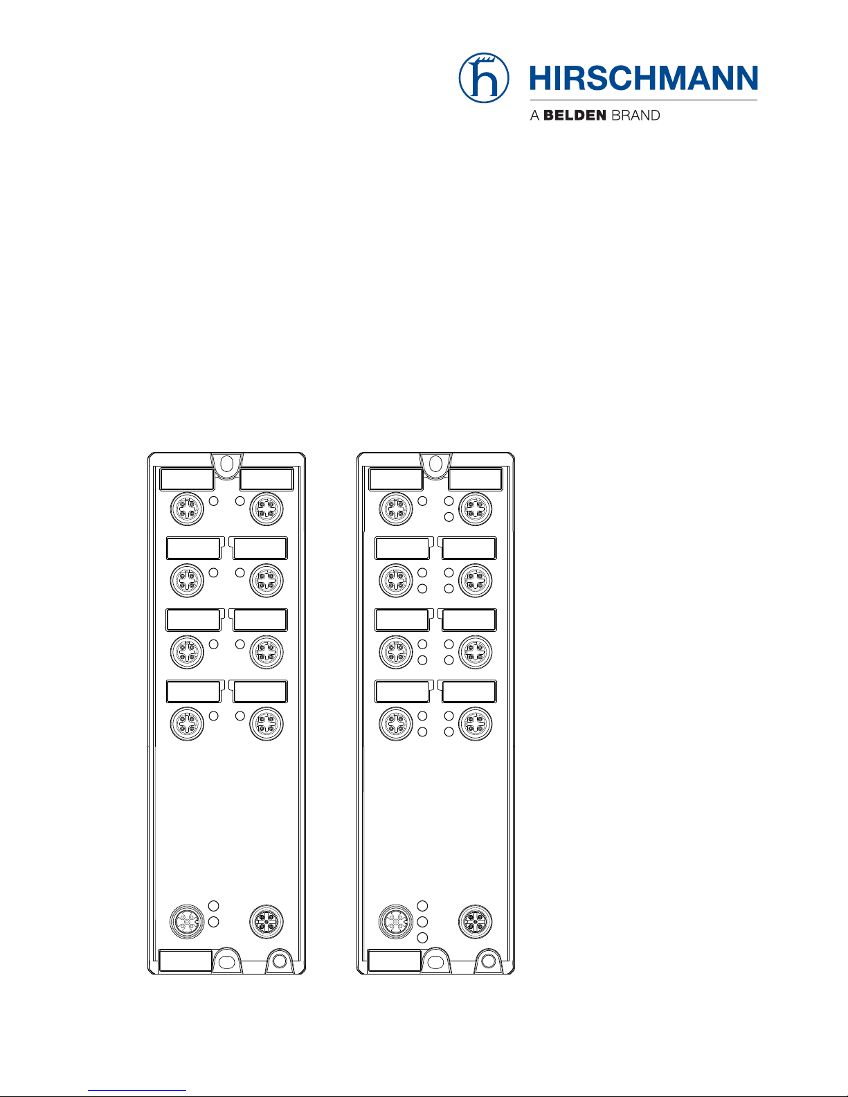
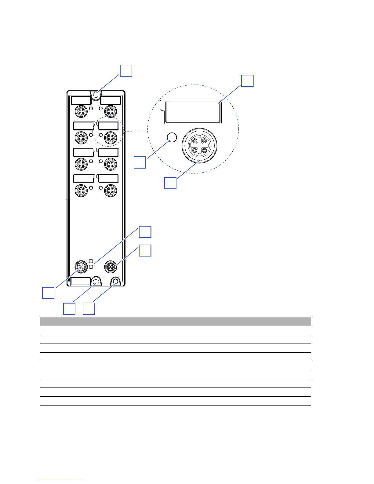
1.2 Device view
1.2.1 Devices without Power over Ethernet
Item Characteristic
1 Slot hole for mounting on a flat surface
2 8 × Indicator plate
3 8 × 4-pin, “D”-coded M12 socket for 10/100 Mbit/s twisted pair connections
4 8 × LED display elements for port status
5 LED display elements for supply voltage
6 M12 interface for the connection of ACA21-M12 (EEC) and ACA22-M12 (EEC)
7 Ground connection
8 Slot hole for mounting on a flat surface
9 Supply voltage connection
1
2
4
5
6
7
8
9
3
Page 15
Installation OCTOPUS 8TX-EEC
Release 04 10/2018
15
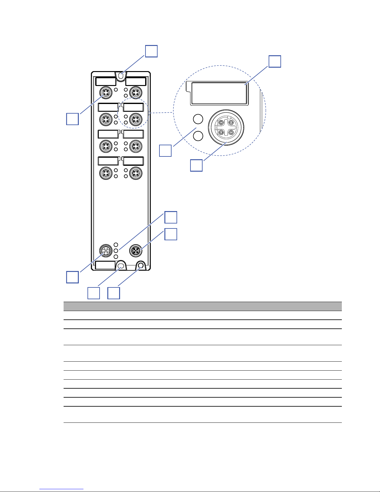
1.2.2 Devices with Power over Ethernet
Item Characteristic
1 Slot hole for mounting on a flat surface
2 8 × Indicator plate
3 7 × 4-pin, “D”-coded M12 socket for 10/100 Mbit/s twisted pair connections
with PoE support
4 15 × LED display elements for port status
PoE status
5 LED display elements for supply voltage
6 M12 interface for the connection of ACA21-M12 (EEC) and ACA22-M12 (EEC)
7 Ground connection
8 Slot hole for mounting on a flat surface
9 Supply voltage connection
10 4-pin, “D”-coded M12 socket for 10/100 Mbit/s twisted pair connections
without PoE support
1
2
4
5
6
7
8
9
10
3
Page 16

16
Installation OCTOPUS 8TX-EEC
Release 04 10/2018
The device supports Power over Ethernet Plus in accordance with
IEEE 802.3at (PoE+) and enables you to supply current to terminal devices
such as IP phones via the twisted-pair cable.
The Power over Ethernet Plus function is activated both globally and on the
PoE-capable ports on delivery.
You will recognize the PoE-capable ports from the printed PoE logo.
The voltage is supplied through the wire pairs transmitting the signal
(phantom voltage). The individual ports are not electrically insulated from
each other.
In accordance with IEEE 802.3af and IEEE 802.3at:
Endpoint PSE
Alternative A.
1.3 Power supply
The supply voltage is connected by means of a 5-pin, “A”-coded M12
connector (e. g. ELWIKA 5012 PG7).
You will find more information here:
“Wiring the connector for the supply voltage” on page 25
1.4 Ethernet ports
You can connect terminal devices and other segments at the ports of the
device via twisted pair cables.
You find information on pin assignments for making patch cables here:
“Pin assignments” on page 17
1.4.1 10/100 Mbit/s twisted pair port
This port is a 4-pin, “D”-coded M12 socket.
The 10/100 Mbit/s twisted pair port allows you to connect network
components according to the IEEE 802.3 10BASE-T/100BASE-TX standard.
This port supports:
Autonegotiation
Autopolarity
Autocrossing (if autonegotiation is activated)
100 Mbit/s half-duplex mode, 100 Mbit/s full duplex mode
10 Mbit/s half-duplex mode, 10 Mbit/s full duplex mode
Delivery state: Autonegotiation activated
Page 17

Installation OCTOPUS 8TX-EEC
Release 04 10/2018
17
The screw threads of the M12 ports are electrically connected to the device
casing.
1.4.2 10/100 Mbit/s PoE port
The PoE ports support the connection and a remote power supply of (for
example) IP phones (Voice-over-IP), webcams, sensors, print servers, and
WLAN access points. With PoE, these end devices are powered via the
twisted pair cable.
This port is a 4-pin, “D”-coded M12 socket.
The 10/100 Mbit/s PoE(+) port allows you to connect network components as
a powered device (PD) according to standards IEEE 802.3 10BASE-T/
100BASE-TX and IEEE 802.3af/at.
This port supports:
Autonegotiation
Autopolarity
Autocrossing
100 Mbit/s half-duplex mode, 100 Mbit/s full duplex mode
10 Mbit/s half-duplex mode, 10 Mbit/s full duplex mode
Power over Ethernet (PoE/PoE+)
Devices are supplied with PoE voltage (54 V DC SELV) using the internal
power supply. PoE voltage via twisted pair cables is supplied using the wire
pairs transmitting the signal (phantom supply).
Delivery state: Autonegotiation activated
The screw threads of the M12 ports are electrically connected to the device
casing.
The PoE voltage is uncoupled from the power supply.
The maximum PoE output of the device is 35 W.
1.4.3 Pin assignments
Pin assignment OCTOPUS 8TX-EEC
Figure Pin Function
1 TD+ Transmit Data+
2 RD+ Receive Data+
3TD− Transmit Data−
4RD− Receive Data−
Casing: shield
1
23
4
Page 18

18
Installation OCTOPUS 8TX-EEC
Release 04 10/2018
Pin assignment OCTOPUS 8TX PoE-EEC
1.5 Display elements
After the supply voltage is set up, the software starts and initializes itself.
During this process, various LEDs light up.
1.5.1 Device state
These LEDs provide information about conditions which affect the operation
of the whole device.
Figure 1: Display elements device status OCTOPUS 8TX-EEC
Figure Pin Function PoE voltage input
1 TD+ Transmit Data + V+
2 RD+ Receive Data + V−
3TD− Transmit Data− V+
4RD− Receive Data− V−
Casing: shield
LED Display Color Activity Meaning
P1 Supply voltage 1 green lights up Supply voltage is on
none Supply voltage is too low
1
23
4
P1
P2
Power
Page 19

Installation OCTOPUS 8TX-EEC
Release 04 10/2018
19
Figure 2: Display elements device status OCTOPUS 8TX PoE-EEC
P2 Supply voltage 2 green lights up Supply voltage is on
none Supply voltage is too low
LED Display Color Activity Meaning
P1 Supply voltage 1green lights up Supply voltage is on
none Supply voltage is too low
P2 Supply voltage 2green lights up Supply voltage is on
none Supply voltage is too low
FAULT PoE status red lights up The combined power output on the PoE ports
exceeds the maximum total power output.
none The total PoE output is sufficient.
LED Display Color Activity Meaning
P1
P2
Power
FAULT
Page 20

20
Installation OCTOPUS 8TX-EEC
Release 04 10/2018
1.5.2 Port Status
These LEDs provide port-related information.
Figure 3: Display elements port status OCTOPUS 8TX-EEC
LED Display Color Activity Meaning
L/D Link state/
data traffic
— none Device detects an invalid or
missing link
green lights up Device detects a valid link
yellow flashing Device is transmitting and/or
receiving data
green/
yellow
flashing alternately Update of the configuration via the
M12 interface
DL DL
Page 21

Installation OCTOPUS 8TX-EEC
Release 04 10/2018
21
Figure 4: Display elements port status OCTOPUS 8TX PoE-EEC
LED Display Color Activity Meaning
L/D Link state/
data traffic
— none Device detects an invalid or
missing link
green lights up Device detects a valid link
yellow flashing Device is transmitting and/or
receiving data
green/
yellow
flashing alternately Update of the configuration via the
M12 interface
PoE — none No powered device connected
green lights up Powered device is supplied with
power
flashes 1 time a period no power supply of the Powered
Device - due to the device
configuration the power output
required by the Powered Device
cannot be provided on this port
flashes 3 times a period No power supply to the powered
device, as PoE is deactivated in
the device management
L/D
PoE
Page 22

22
Installation OCTOPUS 8TX-EEC
Release 04 10/2018
1.6 Configuration interface
1.6.1 ACA-M12 interface
This interface is a 5-pin, “A”-coded M12 socket with shielding.
This interface allows you to connect the ACA21-M12 (EEC) or ACA22M12 (EEC) storage medium.
Figure 5: ACA M12 interface
Note: The USB connector is for temporary connection only.
Pin
1
2
3
4
5
Function
U
in
5 V
N. C. Not used
D- Data GND Ground (0 V)
D+ Data +
1
2
3
4
5
ACA
Page 23

Installation OCTOPUS 8TX-EEC
Release 04 10/2018
23
2Installation
The devices have been developed for practical application in a harsh
industrial environment.
On delivery, the device is ready for operation.
Perform the following steps to install and configure the device:
Checking the package contents
Installing and grounding the device
Wiring the connector for the supply voltage
Operating the device
Connecting data cables
Configuration (optional)
2.1 Checking the package contents
Check whether the package includes all items named in the section
“Scope of delivery” on page 42.
Check the individual parts for transport damage.
2.2 Installing and grounding the device
2.2.1 Mounting on a flat surface
Requirements:
Select the installation site so that the climatic threshold values listed in the
technical data are observed.
See “Technical data” on page 36.
To protect the exposed uninstalled contacts of the components from dirt,
connect the individual system components in a dry and clean working
area.
To sustain the IP65/67 suitability for your device, seal all unused
connections and ports with the provided plastic protection screws. See
“Scope of delivery” on page 42. See “Accessories” on page 43 in case of
an additional demand.
To sustain the IP65/67 suitability for your device, exclusively connect
components with degree of protection IP65/67.
Note: The torque for tightening the plastic protection screws on the device is
5.3 lb-in (0.6 Nm).
Page 24

24
Installation OCTOPUS 8TX-EEC
Release 04 10/2018
Proceed as follows:
Prepare the drill holes at the installation point.
See “Dimension drawings” on page 38.
Mount the device on a level surface with two M4 screws.
2.2.2 Grounding the device
Requirements:
Use a suitable wire diameter for the functional grounding. Hirschmann
recommends a wire diameter of 0.5 mm² (AWG20).
Use toothed washers to ensure good electrical conductivity at the
connection.
Ground the device via an M4 screw.
Note the maximum screw-in depth of 0.295 in (7.5 mm) for OCTOPUS
8TX PoE-EEC devices.
Note: The grounding screw is not included in the scope of delivery.
Figure 6: Functional ground on the device
Proceed as follows:
Grounding the device is by means of a separate ground connection on the
device.
For the position of the ground connection on the device see figure 6.
Ground the device before connecting any other cables.
Disconnect the grounding only after disconnecting all other cables.
Page 25

Installation OCTOPUS 8TX-EEC
Release 04 10/2018
25
2.3 Wiring the connector for the supply voltage
Requirements:
The power supply cable is suitable for the voltage, the current and the
physical load. Hirschmann recommends a wire diameter of 0.5 mm² to
0.75 mm² (AWG20 up to AWG18).
The permitted cable diameter for connector ELWIKA 5012 PG7 is 0.15 in
(4 mm) to 0.23 in (6 mm). To ensure the watertightness of the OCTOPUS
8TX-EEC device, only use voltage supply cables with a diameter within
the specified range.
Make sure that the disconnecting device is easily accessible for
disconnecting the device from the mains voltage.
Note: The supply voltage can be connected redundantly. Both plus
connections are uncoupled. There is no distributed load. With redundant
supply, the power supply unit with the higher output voltage supplies the
device on its own. The supply voltage is electrically isolated from the housing.
PoE devices have no PoE buffering.
Proceed as follows:
Mount the connector for the supply voltage.
2.3.1 Pin assignment OCTOPUS 8TX-EEC
2.3.2 Pin assignment OCTOPUS 8TX PoE-EEC
M12 5-pin (“A”coded)
Pin Function
1 Power supply (1): + 12/24/36 V DC (1)
2 Not used
30V
4 Power supply (2): + 12/24/36 V DC (2)
5 Not used
M12 5-pin (“A”coded)
Pin Function
1 Power supply (1): +24 V DC (1)
2 Not used
30V
4 Power supply (2): +24 V DC (2)
5 Not used
1
23
4
5
1
23
4
5
Page 26

26
Installation OCTOPUS 8TX-EEC
Release 04 10/2018
2.4 Operating the device
When you connect the supply voltage, you start up the device.
2.5 Connecting data cables
Requirements:
Use a shielded CAT5e cable or better.
Use SF/UTP cables as per ISO/IEC 11801:2002.
Use shielded M12 connectors.
Keep the length of the data cables as short as possible.
When using copper cables, provide a sufficient separation between the
power supply cables and the data cables.
Verify that power supply cables and data cables do not run parallel over
longer distances, and that ideally they are installed in separate cable
channels. If reducing the inductive coupling is necessary, verify that the
power supply cables and data cables cross at a 90° angle.
Seal all unused connections and ports with the provided plastic protection
screws. See “Scope of delivery” on page 42. See “Accessories” on
page 43 in case of an additional demand.
Note: The torque for tightening the plastic protection screws on the device is
5.3 lb-in (0.6 Nm).
Proceed as follows:
Connect the data cables according to your requirements.
Make sure the cable shielding is connected to the M12 plug thread.
Page 27

Installation OCTOPUS 8TX-EEC
Release 04 10/2018
27
2.6 Configuration (optional)
The device is immediately ready for operation with its default settings, from
the factory.
You have the option to change the settings according to your requirements
using the ACA M12 interface.
You can find the configuration parameters described in a separate overview.
See table 1 on page 30.
Requirements:
Switch Programming Tool
You can download the software for free on the Internet from the
Hirschmann product pages:
www.hirschmann.com/en/QR/Switch-Programing-Tool
M12 USB Adapter
You can connect the storage medium ACA21-M12 (EEC) or ACA22-M12
(EEC) to your PC using the M12 USB Adapter.
The M12 USB Adapter is available as an accessory.
See “Accessories” on page 43.
ACA21-M12 (EEC) or ACA22-M12 (EEC)
You have the option to transfer configuration data to your device or read
out the configuration using a storage medium.
The storage medium is available as an accessory.
See “Accessories” on page 43.
Proceed as follows:
Connect the storage medium to the device.
Start the Switch Programming Tool.
Select your device variant from the drop-down list “Device Type”.
Modify the parameters in the highlighted areas according to your
requirements.
Page 28

28
Installation OCTOPUS 8TX-EEC
Release 04 10/2018
Save the configuration file to the storage medium.
Page 29

Installation OCTOPUS 8TX-EEC
Release 04 10/2018
29
Disconnect the M12 USB Adapter from your PC.
Disconnect the storage medium from the M12 USB Adapter.
Transfer the configuration data to your device by following these steps:
Verify that the device is switched off.
Connect the storage medium to the device.
Switch on the device.
The device reads the csv file on the storage medium and adopts the
settings. During this time, the LEDs “L/D” flash alternately in yellow/
green.
Page 30

30
Installation OCTOPUS 8TX-EEC
Release
04
10/2018
Parameter Values Default values Comment
global Aging time Aging time in s 300 s Value range 0 ... 1048575
QoS 802.1p mapping VLAN Priority 0 ... 7
Traffic Class 0 ... 3
VLAN Priority
0
1
2
3
4
5
6
7
Traffic Class
1
0
0
1
2
2
3
3
QoS DSCP mapping DSCP value 0 ... 63
Traffic Class 0 ... 3
See table 2 on page 31.
QoS Trust Mode untrusted, trustDot1p, trustIpDscp trustDot1p This also includes VLAN 0 mode for
Profinet applications.
per port Flow control enabled / disabled disabled
Port admin state enabled / disabled enabled
Jumbo frames enabled / disabled disabled Globally enabled if at least one port is
enabled
Broadcast storm protection enabled / disabled disabled Ingress rate limiter
Broadcast storm threshold 0% ... 100% 100%
Multicast storm protection enabled / disabled disabled Ingress rate limiter
Multicast storm threshold 0% ... 100% 100%
Link alarm enabled / disabled disabled
per TP port Autonegotiation enabled / disabled enabled
Speed 100 Mbit/s, 10 Mbit/s 100 Mbit/s Only if autonegotiation is disabled
Duplex mode FDX / HDX FDX Only if autonegotiation is disabled
Autocrossing enabled / disabled enabled Only if autonegotiation is disabled
MDI state MDI, MDI-X MDI-X Only if autonegotiation and
autocrossing is disabled
Table 1: Configuration parameters
Page 31

Installation OCTOPUS 8TX-EEC
Release
04
10/2018
31
per PoE port PoE enable enabled / disabled enabled
PoE priority low, high, critical low critical is highest
(PoE allowed classes) class 0, 1, 2, 3, 4 class 0, 1, 2,
3, 4
all combinations configurable
d2/d10123456
0: 1001233
1: 1001233
2: 1002233
3: 1002233
4: 101223
5: 101223
6: 101223
7: 101223
8: 001233
9: 001233
Table 2: DSCP mapping table
Parameter Values Default values Comment
Table 1: Configuration parameters
Page 32

32
Installation OCTOPUS 8TX-EEC
Release 04 10/2018
2.6.1 Configuration readout
Perform the following steps to start up the device:
Connect the storage medium to your PC using the M12 USB Adapter.
Create a text file in the root directory of the storage medium.
Rename the text file to “ShowRunningConfiguration.txt”.
Disconnect the storage medium from the M12 USB Adapter.
Connect the storage medium to the device.
Restart the device by disconnecting the power supply for a moment.
When the text file “ShowRunningConfiguration.txt” in the root directory
of the device is found, the device creates a file with the current
configuration.
You will find this file in the root directory of the storage medium under the
name “Running_Config.txt”.
Page 33

Installation OCTOPUS 8TX-EEC
Release 04 10/2018
33
3 Monitoring the ambient air temperature
Operate the device below the specified maximum ambient air temperature
exclusively.
See “General technical data” on page 36.
The ambient air temperature is the temperature of the air at a distance of 2 in
(5 cm) from the device. It depends on the installation conditions of the device,
for example the distance from other devices or other objects, and the output
of neighboring devices.
Page 34

34
Installation OCTOPUS 8TX-EEC
Release 04 10/2018
4 Maintenance and service
The device does not require service or maintenance.
Note: Check regularly whether a new version of the Switch Programming
Tool is available. You will find information and software downloads on the
Hirschmann product pages on the Internet
http://belden.catalog.belden.com/en/OCTOPUS
Note: You find information on settling complaints on the Internet at http://
www.beldensolutions.com/en/Service/Repairs/index.phtml.
Page 35

Installation OCTOPUS 8TX-EEC
Release 04 10/2018
35
5Disassembly
Proceed as follows:
Disconnect the data cables.
Disable the supply voltage.
Disconnect the grounding.
Unmount the device.
Page 36

36
Installation OCTOPUS 8TX-EEC
Release 04 10/2018
6 Technical data
6.1 General technical data
Dimensions
W × D × H
OCTOPUS 8TX-EEC 2.40 in × 1.22 in × 7.91 in
(61 mm × 31 mm × 201 mm)
OCTOPUS 8TX PoE-EEC 2.40 in × 1.81 in ×
7.91 in (61 mm ×
46 mm × 201 mm)
Weight OCTOPUS 8TX-EEC approx. 16.58 oz (470 g)
OCTOPUS 8TX PoE-EEC approx. 32.1 oz (910 g)
Power supply
OCTOPUS 8TX-EEC
Safety extra-low voltage (SELV)
Relevant for North America: NEC Class 2 power source max. 2 A.
Rated voltage DC: 12/24/36 V DC
Voltage range DC incl. maximum
tolerances:
9.6 V DC ... 45 V DC
Connection type 5-pin, “A”-coded M12 connector
Power loss buffer > 10 ms
Back-up fuse for each voltage
input when supplied via 1 input
Nominal rating:
Characteristic:
1 A ... 4 A
slow blow
Back-up fuse for each voltage
input when supply is via 2 inputs
Nominal rating:
Characteristic:
1 A ... 2 A
slow blow
Peak inrush current <1.4 A (1ms)
Current integral I²t 0.15 A
2
s
Power supply
OCTOPUS 8TX PoE-EEC
Rated voltage DC: 24 V DC
Voltage range DC incl. maximum
tolerances:
16.8 V DC ... 32 V DC
Connection type 5-pin, “A”-coded M12 connector
Power loss buffer > 10 ms during data
transmission; no power loss
buffer for PoE
Back-up fuse for each voltage
input when supplied via 1 input
Nominal rating:
Characteristic:
3.5 A ... 4 A
slow blow
Back-up fuse for each voltage
input when supply is via 2 inputs
Nominal rating:
Characteristic:
3.5 A ... 4 A
slow blow
Peak inrush current <5 A (1 ms)
Current integral I²t 0,22 A
2
s
Climatic conditions during
operation
Ambient air temperature
a
−40 °F ... +158 °F (−40 °C ...
+70 °C)
Humidity 5 % ... 100 %
(also in condensing
atmospheres)
Air pressure min. 700 hPa (+9842 ft;
+3000 m)
max. 1060 hPa (−1312 ft;
−400 m)
Page 37

Installation OCTOPUS 8TX-EEC
Release 04 10/2018
37
Climatic conditions during
storage
Ambient air temperature
a
−40 °F ... +185 °F (−40 °C ...
+85 °C)
Humidity 5 % ... 100 %
(also in condensing
atmospheres)
Air pressure min. 700 hPa (+9842 ft;
+3000 m)
max. 1060 hPa (−1312 ft;
−400 m)
Protection classes Degree of protection IP65/67
Pollution degree 4
Boot time ca. 5 s
Switching data Data rate 8 × 10/100 Mbit/s
Switching fabric 1.6 Gbit/s
Packet buffer 1.5 Mbit/s
MAC address tabel 16 k
QoS (Queues / Port) 4
a. Temperature of the ambient air at a distance of 2 in (5 cm) from the device
Page 38

38
Installation OCTOPUS 8TX-EEC
Release 04 10/2018
6.2 Dimension drawings
Figure 7: OCTOPUS 8TX-EEC
60,7
2.4
6
0.24
4,5
4,5
0.2
6
0.24
191
7.5
18
0.71
200,5
7.9
13
0.51
0.2
mm
inch
M4
Page 39

Installation OCTOPUS 8TX-EEC
Release 04 10/2018
39
Figure 8: OCTOPUS 8TX PoE-EEC
60,7
2.4
6
0.24
4,5
4,5
0.2
6
0.24
191
7.5
33
1.3
200,5
7.9
13,1
0.52
0.2
mm
inch
M4
Page 40

40
Installation OCTOPUS 8TX-EEC
Release 04 10/2018
6.3 EMC and immunity
EMC interference emission
Radiated emission
EN 55032 Class A
FCC 47 CFR Part 15 Class A
EN 61000-6-4 Fulfilled
Conducted emission
EN 55032 Supply connection Class A
FCC 47 CFR Part 15 Supply connection Class A
EN 61000-6-4 Supply connection Fulfilled
EN 55032 Telecommunication connections Class A
EN 61000-6-4 Telecommunication connections Fulfilled
EMC interference immunity
Electrostatic discharge
EN 61000-4-2
IEEE C37.90.3
Contact discharge ±6 kV
EN 61000-4-2
IEEE C37.90.3
Air discharge ±8 kV
Electromagnetic field
EN 61000-4-3 20 V/m
Fast transients (burst)
EN 61000-4-4 Supply connection ±2 kV
EN 61000-4-4 Data line ±4 kV
Voltage surges - DC supply connection
EN 61000-4-5 line/ground ±2 kV
EN 61000-4-5 line/line ±1 kV
Voltage surges - data line
EN 61000-4-5 line/ground ±2 kV
Conducted disturbances
EN 61000-4-6 150 kHz ... 80 MHz 10 V
Pulse magnetic field
EN 61000-4-9 300 A/m
Stability
IEC 60068-2-6, test Fc Vibration 5 Hz ... 8.4 Hz with
0.14 in. (3.5 mm)
amplitude
8.4 Hz ... 150 Hz with 1 g
IEC 60068-2-27, test Ea Shock 15 g at 11 ms
Page 41

Installation OCTOPUS 8TX-EEC
Release
04
10/2018
41
6.4 Network range
6.5 Power consumption/power output
10/100/1000 Mbit/s twisted pair port
Length of a twisted pair segment max. 328 ft (100 m) (for Cat5e cable)
Table 3: Network range: 10/100/1000 Mbit/s twisted pair port
Name Maximum power consumption Power output
OCTOPUS 8TX-EEC 4.2 W 12.3 Btu (IT)/h
OCTOPUS 8TX PoE-EEC 44 W 150.1 Btu (IT)/h
Page 42

42
Installation OCTOPUS 8TX-EEC
Release 04 10/2018
7 Scope of delivery, order numbers and
accessories
Scope of delivery
Note: The connector ELWIKA 5012 PG7 (933 175-100) supports a
temperature range from −13 °F to +158 °F (−25 °C to +70 °C). It may thus
limit the application range of the overall system.
You can obtain special sockets for the total temperature range and with
the degree of protection IP65/67 and on request.
Order number
Device Scope of delivery
OCTOPUS 8TX-EEC
OCTOPUS 8TX PoE-EEC
Device
1 × Transport protection cap for supply
voltage connection
7 × Protection screws for M12 socket,
plastic
15 × Indicator plates
ELWIKA 5012 PG7 connector
(5-pin M12 socket for power supply)
General safety instructions
Device Order number
OCTOPUS 8TX-EEC 942 150-001
OCTOPUS 8TX PoE-EEC 942 151-001
Page 43

Installation OCTOPUS 8TX-EEC
Release 04 10/2018
43
Accessories
Note that products recommended as accessories may have different
characteristics to those of the device, which may limit the application
range of the overall system. For example, if you add an accessory with
IP20 to a device with IP67, the IP of the overall system is reduced to IP20.
Note: To sustain the IP65/67 suitability for your device, use the
accessories with IP65/67 properties exclusively.
Name Order number
AutoConfiguration Adapter ACA21-M12 (EEC) 943 913-003
AutoConfiguration Adapter ACA22-M12 (EEC) 942 125-001
M12 connector, 4-pin, “D”-coded 934 445-001
M12 USB Adapter 942 199-001
Protection screw for M12 socket, plastic, IP65/67 (25 pieces) 942 057-002
Protection screw for M12 socket, metal, IP65/67 (25 pieces) 942 057-001
Connector ELWIKA 5012 PG7
(5-pin M12 socket for voltage supply)
933 175-100
Transition M12 “D”-coded to RJ45 934 498-001
Connection cable with M12 connectors, 4-pin, “D”-coded
Length 2 m
Length 5 m
Length 10 m
934 578-001
934 578-002
934 578-003
Page 44

44
Installation OCTOPUS 8TX-EEC
Release 04 10/2018
8 Underlying technical standards
The device has an approval based on a specific standard only if the approval
indicator appears on the device casing.
The device generally fulfills the technical standards named in their current
versions.
Name
FCC 47 CFR Part 15 Code of Federal Regulations
UL/IEC 61010-2-201 Safety requirements for electrical equipment for measurement,
control and laboratory use - Part 2-201: Particular requirements
for control equipment.
ISA-12.12.01 Nonincendive Electrical Equipment for Use in Class I and II,
Division 2 and Class III, Divisions 1 and 2 Hazardous
(Classified) Locations.
RCM Australian Regulatory Compliance Mark (RCM)
Australian Radiocommunications Standard 2008,
Radiocommunications Act 1992
ECE Regulation No. 10,
Amendment No. 05, suppl. 01
E type approval for use in vehicles
EN 45545-2 Railway applications - Fire protection on railway vehicles - Part
2: Requirements for fire behavior of materials and components.
EN 50121-4 Railway applications – EMC – Emission and immunity of the
signaling and telecommunications apparatus (Rail Trackside)
EN 50155 Railway applications - Electronic equipment used on rolling
stock
EN 55032 Electromagnetic compatibility of multimedia equipment –
Emission Requirements
EN 60950-1 Information technology equipment – Safety – Part 1: General
requirements
EN 61131-2 Programmable controllers – Part 2: Equipment requirements
and tests
IEEE 802.1D Switching, GARP, GMRP, Spanning Tree
IEEE 802.1D Media access control (MAC) bridges (includes IEEE 802.1p
Priority and Dynamic Multicast Filtering, GARP, GMRP)
IEEE 802.1Q Virtual LANs (VLANs, MRP, Spanning Tree)
IEEE 802.1Q Virtual Bridged Local Area Networks (VLAN Tagging, GVRP)
IEEE 802.3 Ethernet
Page 45

Installation OCTOPUS 8TX-EEC
Release 04 10/2018
45
A Further support
Technical questions
For technical questions, please contact any Hirschmann dealer in your area
or Hirschmann directly.
You find the addresses of our partners on the Internet at http://
www.hirschmann.com.
A list of local telephone numbers and email addresses for technical support
directly from Hirschmann is available at https://
hirschmann-support.belden.com.
This site also includes a free of charge knowledge base and a software
download section.
Hirschmann Competence Center
The Hirschmann Competence Center is ahead of its competitors on three
counts with its complete range of innovative services:
Consulting incorporates comprehensive technical advice, from system
evaluation through network planning to project planning.
Training offers you an introduction to the basics, product briefing and user
training with certification.
You find the training courses on technology and products currently
available at http://www.hicomcenter.com.
Support ranges from the first installation through the standby service to
maintenance concepts.
With the Hirschmann Competence Center, you decided against making any
compromises. Our client-customized package leaves you free to choose the
service components you want to use.
Internet:
http://www.hicomcenter.com
Page 46

46
Installation OCTOPUS 8TX-EEC
Release 04 10/2018
B Open Source Software used in the
product
The product contains, among other things, Open Source Software files, as
defined below, developed by third parties and licensed under an Open
Source Software license.
These Open Source Software files are protected by copyright. Your right to
use the Open Source Software is governed by the relevant applicable Open
Source Software license conditions
Your compliance with those license conditions will entitle you to use the Open
Source Software as foreseen in the relevant license. In the event of conflicts
between other Hirschmann Automation and Control GmbH license
conditions applicable to the product and the Open Source Software license
conditions, the Open Source Software conditions shall prevail. The Open
Source Software is provided royalty-free (i.e. no fees are charged for
exercising the licensed rights). Open Source Software contained in this
product and the respective Open Source Software licenses are stated below.
If Open Source Software contained in this product is licensed under GNU
General Public License (GPL), GNU Lesser General Public License (LGPL),
Mozilla Public License (MPL) or any other Open Source Software license,
which requires that source code is to be made available and such source
code is not already delivered together with the product, you can order the
corresponding source code of the Open Source Software from Hirschmann
Automation and Control GmbH - against payment of the shipping and
handling charges - for a period of at least 3 years since purchase of the
product. Please send your specific request, within three years of the
purchase date of this product, together with the name and ID number of the
product to be found at the label of the product to:
Hirschmann Automation and Control GmbH
Head of R&D
Stuttgarter Str. 45-51
72654 Neckartenzlingen
Germany
Warranty regarding further use of the Open Source Software
Hirschmann Automation and Control GmbH provides no warranty for the
Open Source Software contained in this product, if such Open Source
Software is used in any manner other than intended by Hirschmann
Automation and Control GmbH. The licenses listed below define the
warranty, if any, from the authors or licensors of the Open Source Software.
Page 47

Installation OCTOPUS 8TX-EEC
Release 04 10/2018
47
Hirschmann Automation and Control GmbH specifically disclaims any
warranty for defects caused by altering any Open Source Software or the
product's configuration. Any warranty claims against Hirschmann
Automation and Control GmbH in the event that the Open Source Software
contained in this product infringes the intellectual property rights of a third
party are excluded.
Technical support, if any, will only be provided for unmodified software.
Software contained in the product
The following software components are part of the product depending on the
product and its feature set:
Component Name: Atmel Advanced Software Framework (ASF)
License: Atmel ASF License
Version: 3.25.0
Source Link: http://asf.atmel.com/docs/latest/download.html
Component Name: BSD-style license
License: BSD-style license
Version: R0.09
Source Link: http://elm-chan.org/fsw/ff/archives.html
Component Name: ARM Cortex Microcontroller Software Interface Standard
(CMSIS)
License: ARM CMSIS License
Version: 3.00
Source Link: http://packs.download.atmel.com/
The Licenses in Detail
Atmel Advanced Software Framework (ASF)
Copyright (c) 2014 Atmel Corporation. All rights reserved.
Redistribution and use in source and binary forms, with or without
modification, are permitted provided that the following conditions are met:
1) Redistributions of source code must retain the above copyright notice, this
list of conditions and the following disclaimer.
2) Redistributions in binary form must reproduce the above copyright notice,
this list of conditions and the following disclaimer in the documentation
and/or other materials provided with the distribution.
3) The name of Atmel may not be used to endorse or promote products
derived from this software without specific prior written permission.
4) This software may only be redistributed and used in connection with an
Atmel microcontroller product.
Page 48

48
Installation OCTOPUS 8TX-EEC
Release 04 10/2018
THIS SOFTWARE IS PROVIDED BY ATMEL "AS IS" AND ANY EXPRESS
OR IMPLIED WARRANTIES, INCLUDING, BUT NOT LIMITED TO, THE
IMPLIED WARRANTIES OF MERCHANTABILITY, FITNESS FOR A
PARTICULAR PURPOSE AND NON-INFRINGEMENT ARE EXPRESSLY
AND SPECIFICALLY DISCLAIMED. IN NO EVENT SHALL ATMEL BE
LIABLE OR ANY DIRECT, INDIRECT, INCIDENTAL, SPECIAL,
EXEMPLARY, OR CONSEQUENTIAL DAMAGES (INCLUDING, BUT NOT
LIMITED TO, PROCUREMENT OF SUBSTITUTE GOODS OR SERVICES;
LOSS OF USE, DATA, OR PROFITS; OR BUSINESS INTERRUPTION)
HOWEVER CAUSED AND ON ANY THEORY OF LIABILITY, WHETHER IN
CONTRACT, STRICT LIABILITY, OR TORT (INCLUDING NEGLIGENCE
OR OTHERWISE) ARISING IN ANY WAY OUT OF THE USE OF THIS
SOFTWARE, EVEN IF ADVISED OF THE POSSIBILITY OF SUCH
DAMAGE.
FAT file system (FatFs)
FatFs - FAT file system module R0.09
(C)ChaN, 2011
FatFs module is a generic FAT file system module for small embedded
systems. This is a free software that opened for education, research and
commercial developments under license policy of following terms.
Copyright (C) 2011, ChaN, all right reserved.
The FatFs module is a free software and there is NO WARRANTY. No
restriction on use. You can use, modify and redistribute it for personal, nonprofit or commercial products UNDER YOUR RESPONSIBILITY.
Redistributions of source code must retain the above copyright notice.
ARM Cortex Microcontroller Software Interface Standard (CMSIS)
Copyright (C) 2009-2012 ARM Limited. All rights reserved.
ARM Limited (ARM) is supplying this software for use with Cortex-M
processor based microcontrollers. This file can be freely distributed within
development tools that are supporting such ARM based processors.
THIS SOFTWARE IS PROVIDED “AS IS” NO WARRANTIES, WHETHER
EXPRESS, IMPLIED OR STATUTORY, INCLUDING, BUT NOT LIMITED
TO, IMPLIED WARRANTIES OF MERCHANTABILITY AND FITNESS FOR
A PARTICULAR PURPOSE APPLY TO THIS SOFTWARE. ARM SHALL
NOT, IN ANY CIRCUMSTANCES, BE LIABLE FOR SPECIAL,
INCIDENTAL, OR CONSEQUENTIAL DAMAGES, FOR ANY REASON
WHATSOEVER.
CMSIS is released under the terms of the end user license agreement
(“CMSIS END USER LICENCE AGREEMENT.pdf”). Any user of the
software package is bound to the terms and conditions of the end user
license agreement.
Page 49

Installation OCTOPUS 8TX-EEC
Release 04 10/2018
49
END USER LICENCE AGREEMENT FOR THE CORTEX
MICROCONTROLLER SOFTWARE INTERFACE
STANDARD (CMSIS) SPECIFICATION AND SOFTWARE
THIS END USER LICENCE AGREEMENT (“LICENCE”) IS A LEGAL
AGREEMENT BETWEEN YOU (EITHER A SINGLE INDIVIDUAL, OR
SINGLE LEGAL ENTITY) AND ARM LIMITED (“ARM”) FOR THE USE OF
THE CMSIS SPECIFICATION, EXAMPLE CODE, DSP LIBRARY
SPECIFICATION AND DSP LIBRARY IMPLEMENTATION AS SUCH
TERMS ARE DEFINED BELOW (COLLECTIVELY, THE “ARM
DELIVERABLES”). ARM IS ONLY WILLING TO LICENSE THE ARM
DELIVERABLES TO YOU ON CONDITION THAT YOU ACCEPT ALL OF
THE TERMS IN THIS LICENCE. BY CLICKING “I AGREE”, OR BY
INSTALLING OR OTHERWISE USING OR COPYING THE ARM
DELIVERABLES YOU INDICATE THAT YOU AGREE TO BE BOUND BY
ALL THE TERMS OF THIS LICENCE. IF YOU DO NOT AGREE TO THE
TERMS OF THIS LICENCE, ARM IS UNWILLING TO LICENSE YOU TO
USE THE ARM DELIVERABLES AND YOU MAY NOT INSTALL, USE OR
COPY THE ARM DELIVERABLES.
“CMSIS Specification” means any documentation and C programming
language files defining the application programming interface, naming and
coding conventions of the Cortex Microcontroller Software Interface
Standard (CMSIS) as well as the System View Description (SVD)
documentation and associated XML schema file. Notwithstanding the
foregoing, “CMSIS Specification” shall not include (i) the implementation of
other published specifications referenced in the CMSIS Specification; (ii) any
enabling technologies that may be necessary to make or use any product or
portion there of that complies with the CMSIS Specification, but are not
themselves expressly set forth in the CMSIS Specification (e.g. compiler
front ends, code generators, back ends, libraries or other compiler,
assembler or linker technologies; validation or debug software or hardware;
applications, operating system or driver software; RISC architecture;
processor microarchitecture); (iii) maskworks and physical layouts of
integrated circuit designs; or (iv) RTL or other high level representations of
integrated circuit designs.
“DSP Library Implementation” means any C programming language source
code implementing the functionality of the digital signal processor (DSP)
algorithms and the application programming interface as defined in the DSP
Library Specification. The DSP Library Implementation makes use of CMSIS
application programming interface and therefore is targeted at Cortex-M
class processors.
Page 50

50
Installation OCTOPUS 8TX-EEC
Release 04 10/2018
“DSP Library Specification” means the DSP library documentation and C
programming language file defining the application programming interface of
the DSP Library Implementation. Notwithstanding the foregoing, “DSP
Library Specification” shall not include (i) the implementation of other
published specifications referenced in the DSP Library Specification; (ii) any
enabling technologies that may be necessary to make or use any product or
portion thereof that complies with the DSP Library Specification, but are not
themselves expressly set forth in the DSP Library Specification (e.g. compiler
front ends, code generators, back ends, libraries or other compiler,
assembler or linker technologies; validation or debug software or hardware;
applications, operating system or driver software; RISC architecture;
processor microarchitecture); (iii) maskworks and physical layouts of
integrated circuit designs; or (iv) RTL or other high level representations of
integrated circuit designs.
“Example Code” means any files in C, C++ or ARM assembly programming
languages, associated project and configuration files that demonstrate the
usage of the CMSIS Specification, the DSP Library Specification and the
DSP Library Implementation, for microprocessors or device specific software
applications that are for use with microprocessors.
LICENCE GRANTS.
1.1 ARM hereby grants to you, subject to the terms and conditions of this
Licence, a non-exclusive, nontransferable licence, to;
(i) use and copy the CMSIS Specification for the purpose of developing,
having developed, manufacturing, having manufactured, offering to sell,
selling, supplying or otherwise distributing products that comply with the
CMSIS Specification, provided that you preserve any copyright notices which
are included with, or in, the CMSIS Specification and provided that you do not
use ARM's name, logo or trademarks to market such products;
(ii) use, copy, and modify (solely to the extent necessary to incorporate the
whole or any part of the DSP Library Specification into your documentation),
the DSP Library Specification, for the purpose of developing, having
developed, manufacturing, having manufactured, offering to sell, selling,
supplying or otherwise distributing products that comply with the DSP Library
Specification, and distribute and have distributed any documentation created
by or for you that has been derived from the DSP Library Specification with
such products, provided that you preserve any copyright notices which are
included with, or in, the DSP Library Specification and provided that you do
not use ARM's name, logo or trademarks to market such products;
Page 51

Installation OCTOPUS 8TX-EEC
Release 04 10/2018
51
(iii) use, copy, modify and sublicense the Example Code solely for the
purpose of developing, having developed, manufacturing, having
manufactured, offering to sell, selling, supplying or otherwise distributing
products that comply with either or both the CMSIS Specification and the
DSP Library Specification, provided that you preserve any copyright notices
which are included with, or in, the Example Code and that you do not use
ARM's name, logo or trademarks to market such products;
(iv) use, copy and modify (provided that the logical functionality and the
application programming interface of the DSP Library Implementation are
maintained) the DSP Library Implementation, solely for the purposes of
developing; (a) software applications for use with microprocessors
manufactured or simulated under licence from ARM (“Software
Applications”); and (b) tools that are designed to develop software programs
for use with microprocessors manufactured or simulated under licence from
ARM (“Tools”); and
(v) subject to clause 1.1(vi) below; (a) distribute and sublicense the use of the
DSP Library Implementation (including any modified forms thereof created
under Clause 1.1(iv) above) in binary or source format, solely as
incorporated into Software Library Applications and Tools to third parties;
and (b) sublicense to such third parties the right to use and copy the Tools
for the purposes of developing and distribute software programs for use with
microprocessors manufactured or simulated under licence from ARM.
(vi) CONDITIONS ON REDISTRIBUTION: If you choose to redistribute the
whole or any part of the DSP Library Implementation as incorporated into
Software Library Applications or Tools, you agree to; (a) ensure that the DSP
Library Implementation is licensed for use only as part of Software Library
Applications and Tools and only for use with microprocessors manufactured
or simulated under licence from ARM; (b) not to use ARM's name, logo or
trademarks to market Software Applications and Tools; and (c) include valid
copyright notices on Software Applications and Tools, and preserve any
copyright notices which are included with, or in, the DSP Library
Implementation.
2. RESTRICTIONS ON USE OF THE ARM DELIVERABLES.
PERMITTED USERS: The ARM Deliverables shall be used only by you
(either a single individual, or single legal entity) your employees, or by your
on-site bona fide sub-contractors for whose acts and omissions you hereby
agree to be responsible to ARM for to the same extent as you are for your
employees, and provided always that such sub-contractors; (i) are
contractually obligated to use the ARM Deliverables only for your benefit, and
(ii) agree to assign all their work product and any rights they create therein in
the supply of such work to you.
Page 52

52
Installation OCTOPUS 8TX-EEC
Release 04 10/2018
COPYRIGHT AND RESERVATION OF RIGHTS: The ARM Deliverables are
owned by ARM or its licensors and are protected by copyright and other
intellectual property laws and international treaties. The ARM Deliverables
are licensed not sold. Except as expressly licensed herein, you acquire no
right, title or interest in the ARM Deliverables or any intellectual property
therein. In no event shall the licences granted herein be construed as
granting you, expressly or by implication, estoppels or otherwise, a licence to
use any ARM technology except the ARM Deliverables.
3. SUPPORT.
ARM is not obligated to support the ARM Deliverables but may do so entirely
at ARM's discretion.
4. NO WARRANTY
YOU AGREE THAT THE ARM DELIVERABLES ARE LICENSED "AS IS",
AND THAT ARM EXPRESSLY DISCLAIMS ALL REPRESENTATIONS,
WARRANTIES, CONDITIONS OR OTHER TERMS, EXPRESS,IMPLIED
OR STATUTORY, INCLUDING WITHOUT LIMITATION THE IMPLIED
WARRANTIES OF NONINFRINGEMENT, SATISFACTORY QUALITY,
AND FITNESS FOR A PARTICULAR PURPOSE. THE ARM
DELIVERABLES MAY CONTAIN ERRORS. ARM RESERVES THE RIGHT
TO INCORPORATE MODIFICATIONS TO THE ARM DELIVERABLES IN
LATER REVISIONS OF THEM, AND TO MAKE IMPROVEMENTS OR
CHANGES IN THE ARM DELIVERABLES AT ANY TIME.
5. LIMITATION OF LIABILITY
THE MAXIMUM LIABILITY OF ARM TO YOU IN AGGREGATE FOR ALL
CLAIMS MADE AGAINST ARM IN CONTRACT, TORT OR OTHERWISE
UNDER OR IN CONNECTION WITH THE SUBJECT MATTER OF
THISLICENCE SHALL NOT EXCEED THE GREATER OF (I) THE TOTAL
OF SUMS PAID BY YOU TO ARM (IF ANY) FOR THIS LICENCE AND (II)
US$10.00. THE LIMITATIONS, EXCLUSIONS AND DISCLAIMERS INTHIS
LICENCE SHALL APPLY TO THE MAXIMUM EXTENT ALLOWED BY
APPLICABLE LAW.
6. U.S. GOVERNMENT END USERS
US Government Restrictions: Use, duplication, reproduction, release,
modification, disclosure or transfer of this commercial product and
accompanying documentation is restricted in accordance with the terms of
this Licence.
7. TERM AND TERMINATION
7.1 This Licence shall remain in force until terminated in accordance with the
terms of Clause 7.2 or Clause 7.3 below.
7.2 Without prejudice to any of its other rights if you are in breach of any of
the terms and conditions of this Licence then ARM may terminate this
Licence immediately upon giving written notice to you. You may terminate
this Licence at any time.
Page 53

Installation OCTOPUS 8TX-EEC
Release 04 10/2018
53
7.3 This Licence shall immediately terminate and shall be unavailable to you
if you or any party affiliated to you asserts any patents against ARM, ARM
affiliates, third parties who have a valid licence from ARM for the ARM
Deliverables, or any customers or distributors of any of them based upon a
claim that your (or your affiliate) patent is Necessary to implement the CMSIS
Specification or DSP Library Specification. In this Licence; (i) "affiliate"
means any entity controlling, controlled by or under common control with a
party (in fact or in law, via voting securities, management control or
otherwise) and "affiliated" shall be construed accordingly; (ii) "assert" means
to allege infringement in legal or administrative proceedings, or proceedings
before any other competent trade, arbitral or international authority; (iii)
“Necessary” means with respect to any claims of any patent, those claims
which, without the appropriate permission of the patent owner, will be
infringed when implementing the CMSIS Specification or DSP Library
Specification because no alternative, commercially reasonable,
noninfringing way of implementing the CMSIS Specification or DSP Library
Specification is known.
7.4 Upon termination of this Licence, you shall stop using the ARM
Deliverables and destroy all copies of the ARM Deliverables in your
possession. The provisions of clauses 5, 6, 7, and 8 shall survive termination
of this Licence.
8. GENERAL.
This Licence is governed by English Law. Except where ARM agrees
otherwise in a written contract signed by you and ARM, this is the only
agreement between you and ARM relating to the ARM Deliverables and it
may onlybe modified by written agreement between you and ARM. Except as
expressly agreed in writing, this Licence may not be modified by purchase
orders, advertising or other representation by any person. If any clause
orsentence in this Licence is held by a court of law to be illegal or
unenforceable the remaining provisions of this Licence shall not be affected
thereby. The failure by ARM to enforce any of the provisions of this Licence,
unlesswaived in writing, shall not constitute a waiver of ARM's rights to
enforce such provision or any other provision of this Licence in the future.
This Licence may not be assigned without the prior written consent of ARM.
ARM contract reference LEC-PRE-00489-V6.0
06 December, 2010
Page 54

 Loading...