

Page 1
iSCOUT
expert compact
Graphics console
Operator's Manual
Issue 8/2008 Rev. C
This document is listed under Order No.
50 650 19 0201e (LinkBelt278)
Contents
General Information
Important Notes
System Description
Configuration Setup
Inspection checks
before start-up
Service and Maintenance
Troubleshooting
Appendix
Page 2

Operation Manual iSCOUT expert compact (Link-Belt 278)
© 2008 HIRSCHMANN Automation and Control GmbH · Branch Office Ettlingen · eMail: info.ecs@hirschmann.de · www.hirschmann-usa.com 2
50 650 19 0201e_Rev C (LinkBelt278).doc / 2008-08-18 / Rev. C / rk
TABLE OF CONTENTS
1. General Information.................................................................3
2. Important Notes........................................................................4
3. System Description..................................................................5
3.1 System Function.........................................................................6
3.2 Operator's Console ....................................................................7
3.3 Displays and operating elements ...............................................8
3.4 Description of the status symbols ............................................14
4. Configuration Setup...............................................................15
4.1 Interactive operating mode setup.............................................16
4.2 Quick adjusting the reeving or selecting the hoist....................22
4.3 Programming geometrical limits ...............................................24
4.3.1 Radius limitation ......................................................................25
4.3.2 Tip height limitation ..................................................................27
4.3.3 Boom angle limitation...............................................................29
4.3.4 Slewing angle limitation / Virtual wall definition........................31
Slewing angle limitation............................................................31
Virtual wall definition ................................................................33
5. Pre-operational Inspection....................................................36
5.1 Operation .................................................................................38
6. Service and Maintenance ......................................................39
6.1 Info / Service Menus.................................................................40
7. Troubleshooting.....................................................................44
7.1 General Notes ..........................................................................44
7.2 Malfunction Table.....................................................................45
Appendix: Menu overview calibration menus ..............................50
Appendix: Important Instructional Notes......................................53
Page 3

System Description
© 2008 HIRSCHMANN Automation and Control GmbH · Branch Office Ettlingen · eMail: info.ecs@hirschmann.de · www.hirschmann-usa.com 3
50 650 19 0201e_Rev C (LinkBelt278).doc / 2008-08-18 / Rev. C / rk
1. GENERAL INFORMATION
The purpose of the iFLEX5 load moment limitation and control system with iSCOUT expert compact
console (hereafter referred to as LMI) is to provide the crane operator with important information
necessary for the operation of the crane within the areas of operation specified by the manufacturer.
The LMI uses a variety of different sensors to monitor different crane functions and communicates the
crane performance data to the crane operator on a continuous basis. This data changes constantly in
connection with the crane movements.
If the crane nears its safe load limit, the system will warn the crane operator by means of both acoustic and optical signals. In addition, as soon as the crane reaches an unauthorized operating status, all
crane movements will be switched off that would increase the load moment on the crane.
The PAT iFLEX5 system uses a graphics operator interface, the functionality of which is determined
by the crane manufacturer. The selection of the programmed functions is considerably simplified by
the use of symbols.
The load moment limitation and control system based on the PAT iFLEX5 is made up of main com-
ponents that are connected via a CAN bus.
The manufacturer reserves the right to modify the contents of this manual without notice. Hirschmann offers no guarantee
whatsoever for this material, including guarantees with reference to commercial availability and suitability for particular applications. Hirschmann shall not be liable for errors contained herein or for identical or consequential damages in connection
with the furnishing, performance, or use of this manual. This manual is protected by copyright. All rights reserved. The manual may not be copied, reproduced or translated into another language, neither whole nor in part, without advance written
authorization from Hirschmann.
Page 4
System Description
© 2008 HIRSCHMANN Automation and Control GmbH · Branch Office Ettlingen · eMail: info.ecs@hirschmann.de · www.hirschmann-usa.com 4
50 650 19 0201e_Rev C (LinkBelt278).doc / 2008-08-18 / Rev. C / rk
2. IMPORTANT NOTES
The LMI is an operating aid that warns the crane operator of imminent overloading or of the approach
of the hook block, hook ball, or load to the boom head, in order to avoid possible property damage or
injury to personnel.
The device is not, nor is it intended to be, a substitute for good operator judgment and/or experience,
nor does it remove the need for utilizing only recognized safe procedures during crane operations.
The crane operator continues to bear ultimate responsibility for safe operation of the crane.
He must ensure that he fully understands and follows the displayed notes and instructions
in their entirety.
Before beginning crane operations, the crane operator must carefully read and understand
the entire manual in order to ensure that he is aware of the operation and limitations of both
the LMI and the crane itself.
Proper functioning is dependent upon proper daily inspection and observation of the operating instructions set forth in the manual.
The LMI is not able to provide aid to the crane operator unless it has been properly adjusted
and unless the correct load capacity chart and the correct operating code have been entered for the respective rigging configuration. The accuracy of the LMI settings must be
guaranteed before beginning crane work in order to avoid damage to property and severe
or even fatal injuries to personnel.
This system can be equipped with an external key-operated switch located in the crane operator's cab. This key-operated switch overrides control lever function switch-off by the LMI
or by the hoist limit switch system. This switch may only be used during emergency situations, and even then only by authorized personnel. Failure to observe these instructions
could result in damage to property and severe or even fatal injuries to personnel.
The LMI cannot perform correctly unless it has been properly adjusted. The prerequisite for
this is making conscientious and correct entries during the set-up procedure, in accordance with the actual configuration of the crane. The accuracy of the LMI settings must be
ensured before beginning crane work in order to avoid damage to property and severe or
even fatal injuries to personnel.
Page 5
System Description
© 2008 HIRSCHMANN Automation and Control GmbH · Branch Office Ettlingen · eMail: info.ecs@hirschmann.de · www.hirschmann-usa.com 5
50 650 19 0201e_Rev C (LinkBelt278).doc / 2008-08-18 / Rev. C / rk
3. SYSTEM DESCRIPTION
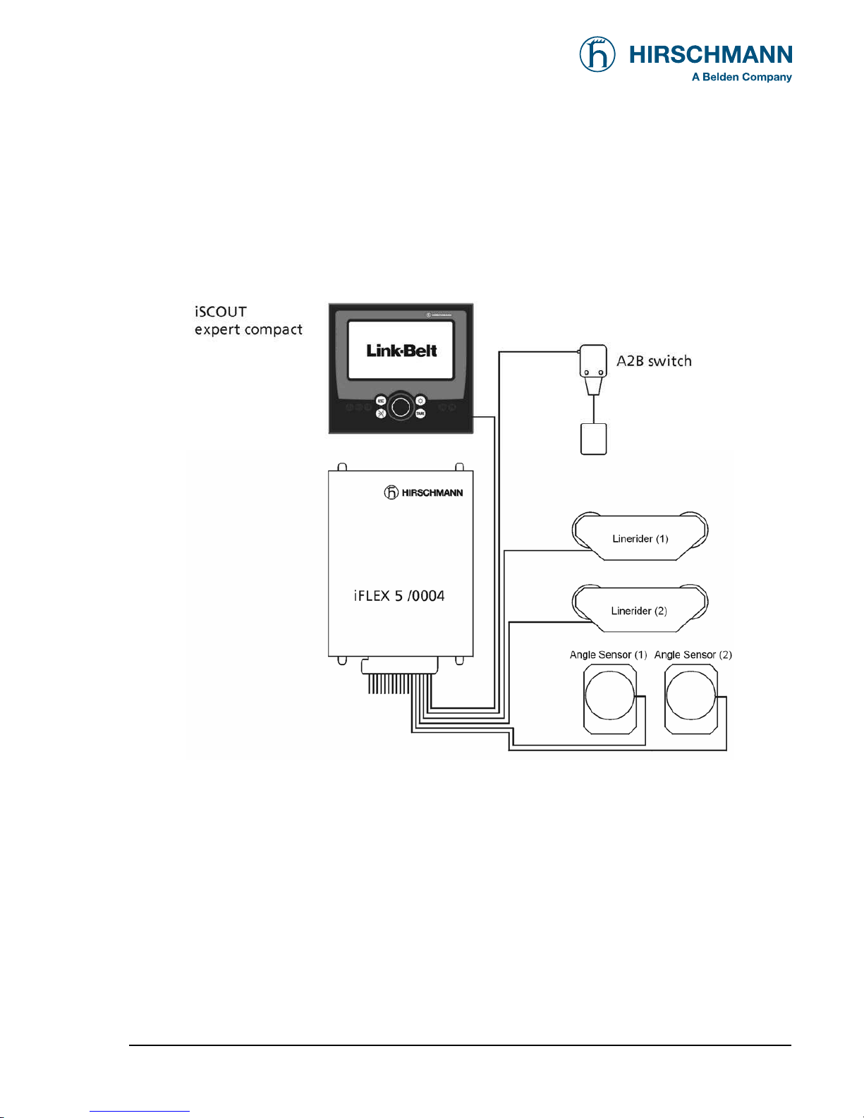
The PAT load moment limitation and control system consist of an iFLEX5 central unit, an iSCOUT
expert compact CAN console and various sensors for collection the measured values.
Fig. 1: Components of the LMI system with iFLEX5
The system operates on the principle of reference/real comparison. The actual value is compared
with the calculated reference values and evaluated by the system. An overload warning signal is triggered on the display and operating console once limit values are reached. All crane movements that
increase the load moment are switched off at the same time.
The crane-specific data specified by the manufacturer, such as load capacity charts, boom weights,
centers of gravity and dimensions, are stored in the central data memory. This data is the reference
information used to calculate the operating conditions.
The boom angle is registered by means of an angle sensor that is mounted on the boom. The crane
load is determined indirectly with the aid of force and angle sensors.
Page 6
System Description
© 2008 HIRSCHMANN Automation and Control GmbH · Branch Office Ettlingen · eMail: info.ecs@hirschmann.de · www.hirschmann-usa.com 6
50 650 19 0201e_Rev C (LinkBelt278).doc / 2008-08-18 / Rev. C / rk
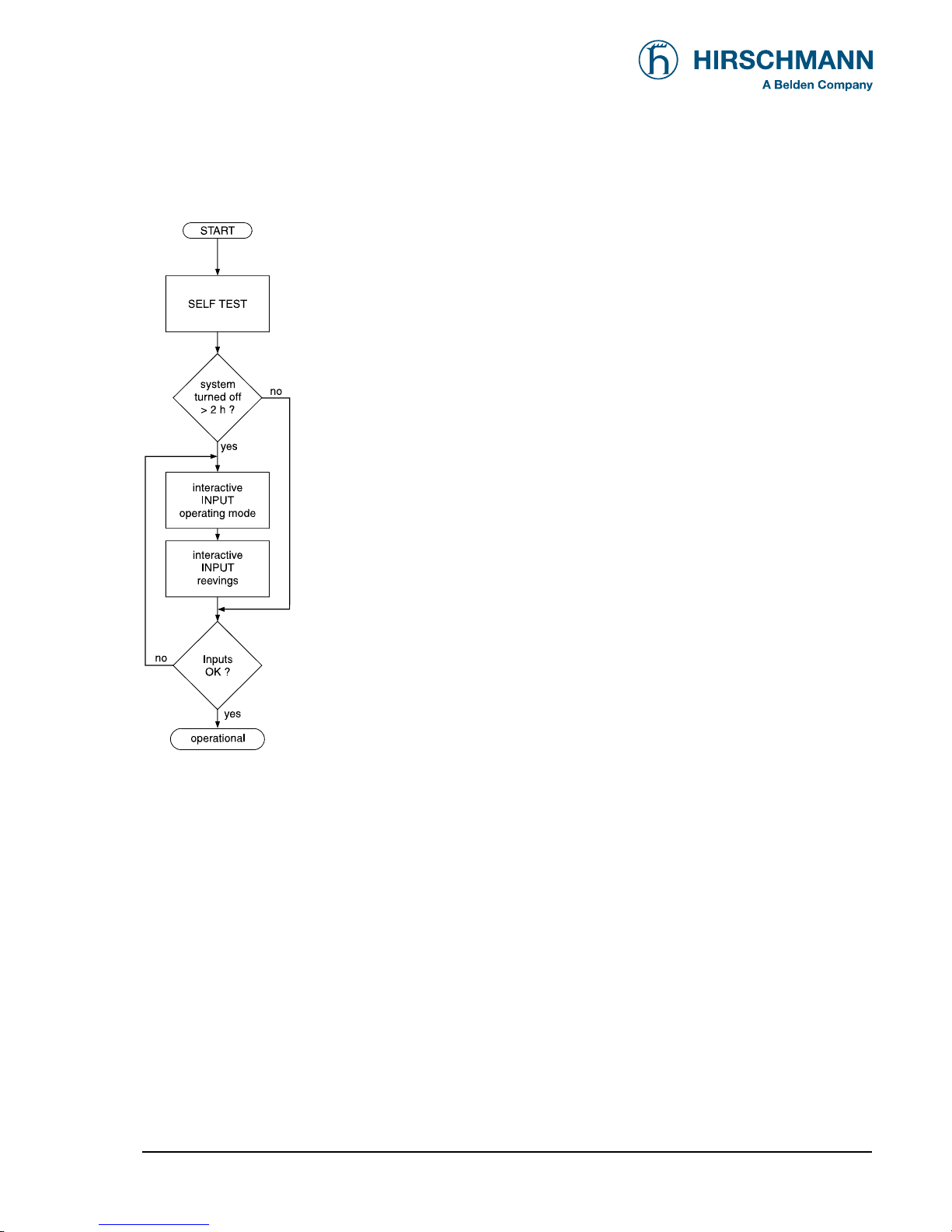
3.1 SYSTEM FUNCTION
Upon switching on, the system starts with an automatic test of the LMI system, of lamps
and audible alarm. During the test, the LC (liquid crystal) display shows the start screen.
If the system was turned off for more than the maximum time, the setup configuration
must be entered after the system test. (⇒ chapter 4)
First, the operating mode is determined by a step-by-step review of the rigging states.
Next, input of the reeving.
Now the LC display shows all inputs and awaits acknowledgment or cancelling.
Upon acknowledgment of the inputs the system is ready for operation.
In the event of a disruption, a corresponding error code "E##" will appear on the Data display (1). (> refer to error code table)
Page 7

System Description
© 2008 HIRSCHMANN Automation and Control GmbH · Branch Office Ettlingen · eMail: info.ecs@hirschmann.de · www.hirschmann-usa.com 7
50 650 19 0201e_Rev C (LinkBelt278).doc / 2008-08-18 / Rev. C / rk
3.2 OPERATOR'S CONSOLE
The console has several functions:
• Entries into the LMI system made by the crane operator
(mode of operation, number of reevings, etc.)
• Important data and information displays during crane operation
• Input of geometry limit values and cut-off if exceeding limits
• Call-up and display of system information for operator and service personnel
The operating console is located in the operator's cab in plain view of the crane operator. All displays
have background illumination for enhanced ease of recognition. The console contains various operating elements as well as a multifunction LC display, all of which are described in detail in Chapter 3.3.
The background illumination of the operating elements and the LC display is manually adjustable in
accordance with present light levels.
Page 8

System Description
© 2008 HIRSCHMANN Automation and Control GmbH · Branch Office Ettlingen · eMail: info.ecs@hirschmann.de · www.hirschmann-usa.com 8
50 650 19 0201e_Rev C (LinkBelt278).doc / 2008-08-18 / Rev. C / rk
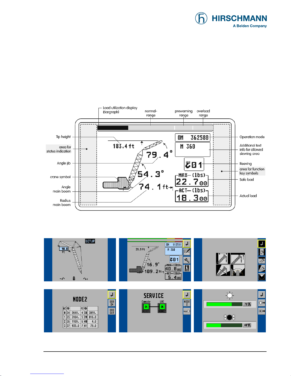
3.3 Displays and operating elements
Figure 1 shows the display and operating elements of the iSCOUT expert compact console.
The numbers in this illustration correspond to the numbers of the following functional characteristics
for each element:
Fig. 2
1 Data display
2 Utilization display field (bar graph)
3 Prewarning lamp (load moment)
4 Overload warning light (load moment)
5 "Hoist limit" warning light (A2B)
6 "LMI override" warning light
7 "Hoist limit override" warning light
8 "ESC" pushbutton (to main menu)
9 "Settings > Brightness" pushbutton
10 "Alarm off" pushbutton
11 "TARE" pushbutton
12 Rotary selection wheel with push button
Page 9
System Description
© 2008 HIRSCHMANN Automation and Control GmbH · Branch Office Ettlingen · eMail: info.ecs@hirschmann.de · www.hirschmann-usa.com 9
50 650 19 0201e_Rev C (LinkBelt278).doc / 2008-08-18 / Rev. C / rk
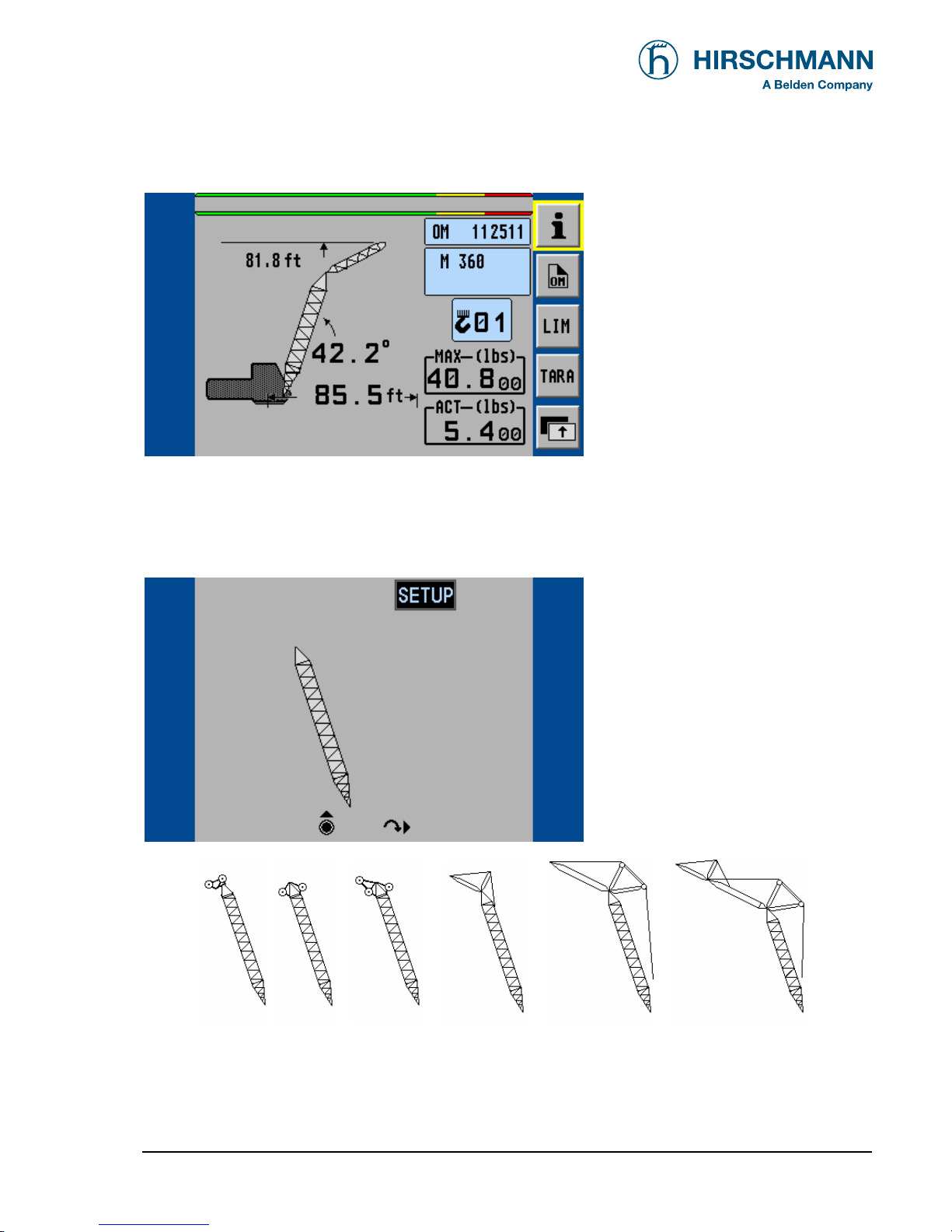
(1) Data display
The Data display (1) is a 6.5" LC color graphics display with background illumination which shows
required data such as load values, geometry and crane data, symbols, etc., depending on the respective operating status.
Normal LMI display:
(Illustration in black/white)
Other display examples:
Set-up Menu (mode of operation) Standard LMI screen Limits Menu
iNFO Menu (CAN Node 2) Service Menu (Bus Information) Brightness Setting Menu
A detailed description of the symbols and displays can be found both in the individual chapters and in the Appendix to this
manual.
Page 10
System Description
© 2008 HIRSCHMANN Automation and Control GmbH · Branch Office Ettlingen · eMail: info.ecs@hirschmann.de · www.hirschmann-usa.com 10
50 650 19 0201e_Rev C (LinkBelt278).doc / 2008-08-18 / Rev. C / rk
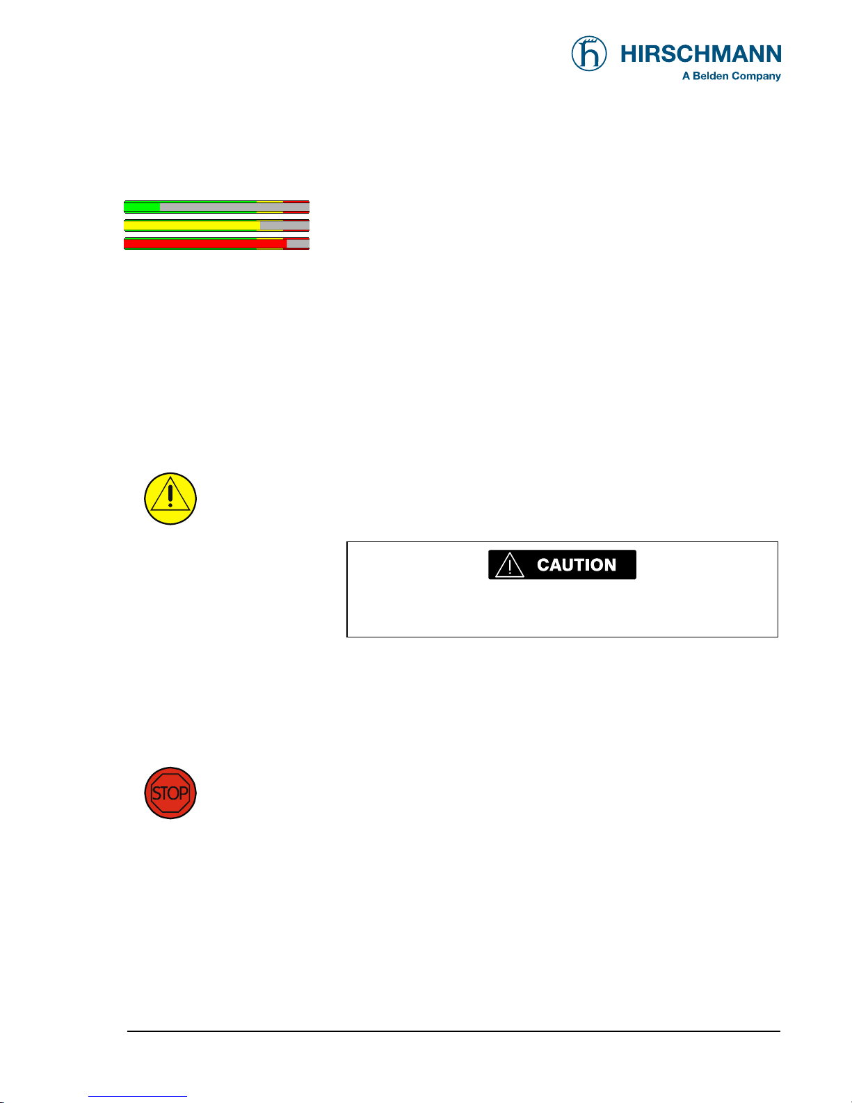
(2) Utilization display (bar graph)
The Utilization display (bar graph) indicates how much of the per-
mitted load (nominal moment) is currently being utilized. The load
display also undergoes constant alteration because the nominal
moment changes continuously during lifting operation.
The bar graph is filled with various colors:
green: "safe" range (0...90% of the nominal moment)
yellow: "pre-warning" range (90...100% of the nominal moment)
red: "overload range" (>100% of the nominal moment)
(3) "Load moment prewarning" light
This yellow prewarning light comes up when the load on the crane
amounts to 90% - 100% of the respective nominal carrying load,
which indicates that an overload situation is immediately pending.
For the crane operator, this means that the crane work can
continue only with the greatest amount of caution.
(4) "Overload" w arning light
This red Overload warning light indicates to the crane operator that
an overload condition has occurred. It lights up when the crane
load has reached 100% of maximum load carrying capacity permitted for the current operating status. The acoustic alarm sounds.
The load-moment-increasing crane movements are switched off at
the same time.
Page 11
System Description
© 2008 HIRSCHMANN Automation and Control GmbH · Branch Office Ettlingen · eMail: info.ecs@hirschmann.de · www.hirschmann-usa.com 11
50 650 19 0201e_Rev C (LinkBelt278).doc / 2008-08-18 / Rev. C / rk
(5) "Hoist limit" w arning light
This red warning light lights up when the hoist limit switch contacts
open, i.e. when a hoist limit situation has occurred. The acoustic
alarm sounds and load-moment-increasing crane movements are
switched off at the same time.
A hoist limit situation occurs when the hook block comes
into contact with the boom head. The danger exists in such
situations that the hoist rope will break, causing the load to
fall. A hoist limit situation could arise from the load being
pulled against the boom head or from the boom being extended or lowered without the hoist rope being spooled off
the drum(s).
(6) "Load limit device (LMI) override" warning light
This red warning light lights up when the switch-off function of the
LMI system has been manually overridden.
(7) "Hoist limit sw itch override" warning light
This red warning light lights up when the switch-off function of the
hoist limit switch has been manually overridden.
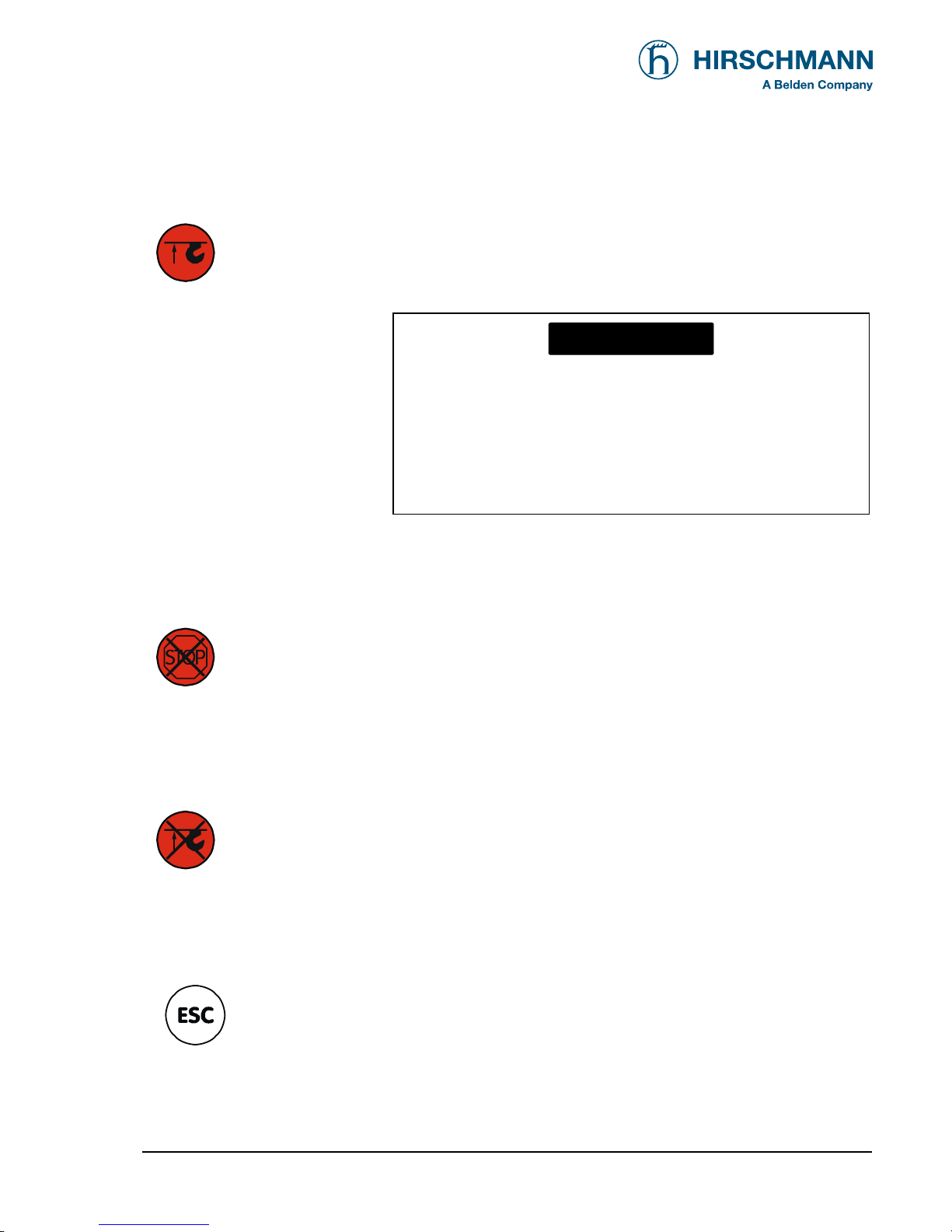
(8) "ESC (Escape)" key
Push button for returning to the normal LMI display
NOTE
Page 12
System Description
© 2008 HIRSCHMANN Automation and Control GmbH · Branch Office Ettlingen · eMail: info.ecs@hirschmann.de · www.hirschmann-usa.com 12
50 650 19 0201e_Rev C (LinkBelt278).doc / 2008-08-18 / Rev. C / rk
(9) "Brightness setting" pushbutton
The brightness and thus the legibility of the data display and the
buttons can be adjusted at any time with this pushbutton.
(10) "Buzzer off" key
The acoustic alarm can be suppressed by pressing this pushbutton, although not before the alarm has sounded a minimum of 5 s.
The alarm will sound again after approximately 10 s if the cause of
it being triggered is still present.
The acoustic alarm sounds in the following situations:
System test, overload condition, imminence of a hoist limit situation (when the
hoist limit switch function is registered by the LMI system), disruption of the LMI
system, or presence of operating errors recognized by the system.
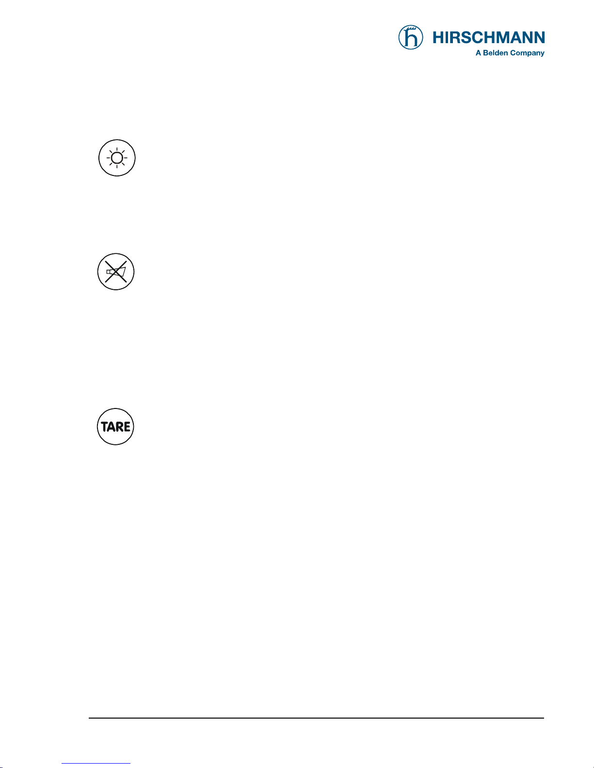
(11) "TARE" key
The "TARE" key is for the purpose of outputting the net load on the
Actual load display. The net load is the current load minus the load
hoisting equipment and the hook block. The "TARE" pushbutton
must be pressed before the hoisting process is initiated.
After the button is actuated, the Current Load display is set to zero (tared). After
the load has been raised, the Current Load display will then show the net load
(payload). As soon as the working radius (by angle or radius modification) is modified, the display shows again the current load and the taring function is completed.
Note: The current load includes the hook block, the hoist rope and all of the load
lifting tackle. The net load is the current load on the hook without load lifting
tackle. Display errors can be caused by the effects of environmental influences
such as wind on the boom or the load.
Page 13
System Description
© 2008 HIRSCHMANN Automation and Control GmbH · Branch Office Ettlingen · eMail: info.ecs@hirschmann.de · www.hirschmann-usa.com 13
50 650 19 0201e_Rev C (LinkBelt278).doc / 2008-08-18 / Rev. C / rk
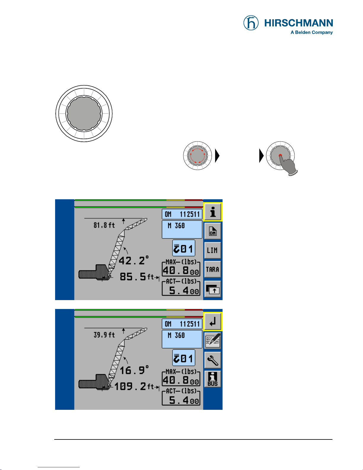
(12) Rotary selection wheel with pushbutton
This central rotary selection wheel is used to navigate within the
menu structure.
At first select the desired soft key symbol .
By pressing the button of the rotary wheel the marked function is
carried out.
select
symbol
▼ LMI main screen (1st level of function keys)
< show info screens
< start operation mode setup
< set geometrical limits
< start TARE function
< switch to 2nd level of function keys
▼ LMI main screen (2nd level of function keys)
< back to the previous menu
< show LMI value screen
< show service menu (code required)
< show CAN-bus menu
Page 14

System Description
© 2008 HIRSCHMANN Automation and Control GmbH · Branch Office Ettlingen · eMail: info.ecs@hirschmann.de · www.hirschmann-usa.com 14
50 650 19 0201e_Rev C (LinkBelt278).doc / 2008-08-18 / Rev. C / rk
3.4. Description of the status symbols
Symbol for LMI error (in connection with fault code)
Symbol for bus error
Hoist limit switch has come into action (A2B)
Back-up battery for console RAM memory is low.
Ask field service to replace lithium battery 3V on printed circuit board.
Back-up battery for iFLEX5 RAM memory is low.
Ask field service to replace lithium battery 3V on printed circuit board.
Symbol radius limitation
• continuously visible:
radius limitation active
• blinking:
range limits exceeded
(⇒ see chapter 4.3.1)
Symbol height limitation:
• continuously visible:
height limitation active
• blinking:
height limit exceeded
(⇒ see chapter 4.3.2)
Symbol boom angle limitation:
• continuously visible:
boom angle limitation active
• blinking:
angle limits exceeded
(⇒ see chapter 4.3.3)
Symbol slewing angle limitation:
• continuously visible:
slewing angle limitation active
• blinking:
slewing angle limits exceeded
(⇒ see chapter 4.3.4.1)
Symbol work area definition:
• continuously visible:
work area definition active
• blinking:
work area limits exceeded
(⇒ see chapter 4.3.4.2)
Page 15
Programming
© 2008 HIRSCHMANN Automation and Control GmbH · Branch Office Ettlingen · eMail: info.ecs@hirschmann.de · www.hirschmann-usa.com 15
50 650 19 0201e_Rev C (LinkBelt278).doc / 2008-08-18 / Rev. C / rk
4. Configuration SETUP
It is necessary to setup the system by entering the respective mode of configuration every time the
crane structure is modified.
The SLI cannot perform correctly unless it has been properly adjusted. The prerequisite for
this is making conscientious and correct entries during the setup procedure, in accordance
with the actual configuration of the crane. The accuracy of the SLI settings must be ensured
before beginning crane work in order to avoid damage to property and severe or even fatal
injuries to personnel.
The correct setting is of utmost importance for the proper functioning of the system and the
crane.
Therefore, only operators who are thoroughly familiar with the crane and the operation of
the system should execute this configuration procedure.
The setup procedure is cancelled any time by pressing key (8) "ESC". The system, however, is only
ready for operation, if the procedure has been completed and the inputs have been confirmed.
During the programming procedure the Load Moment Prewarning Light (3) and the Load Moment
Limit Light (4) will light up and the crane movements will be interrupted.
If the system is turned off all adjustments remain stored. When turning the system on again these
adjustments can be acknowledged by merely pressing the "OK" key in the confirmation screens (provided that the crane configuration has not been modified)
Page 16
Programming
© 2008 HIRSCHMANN Automation and Control GmbH · Branch Office Ettlingen · eMail: info.ecs@hirschmann.de · www.hirschmann-usa.com 16
50 650 19 0201e_Rev C (LinkBelt278).doc / 2008-08-18 / Rev. C / rk
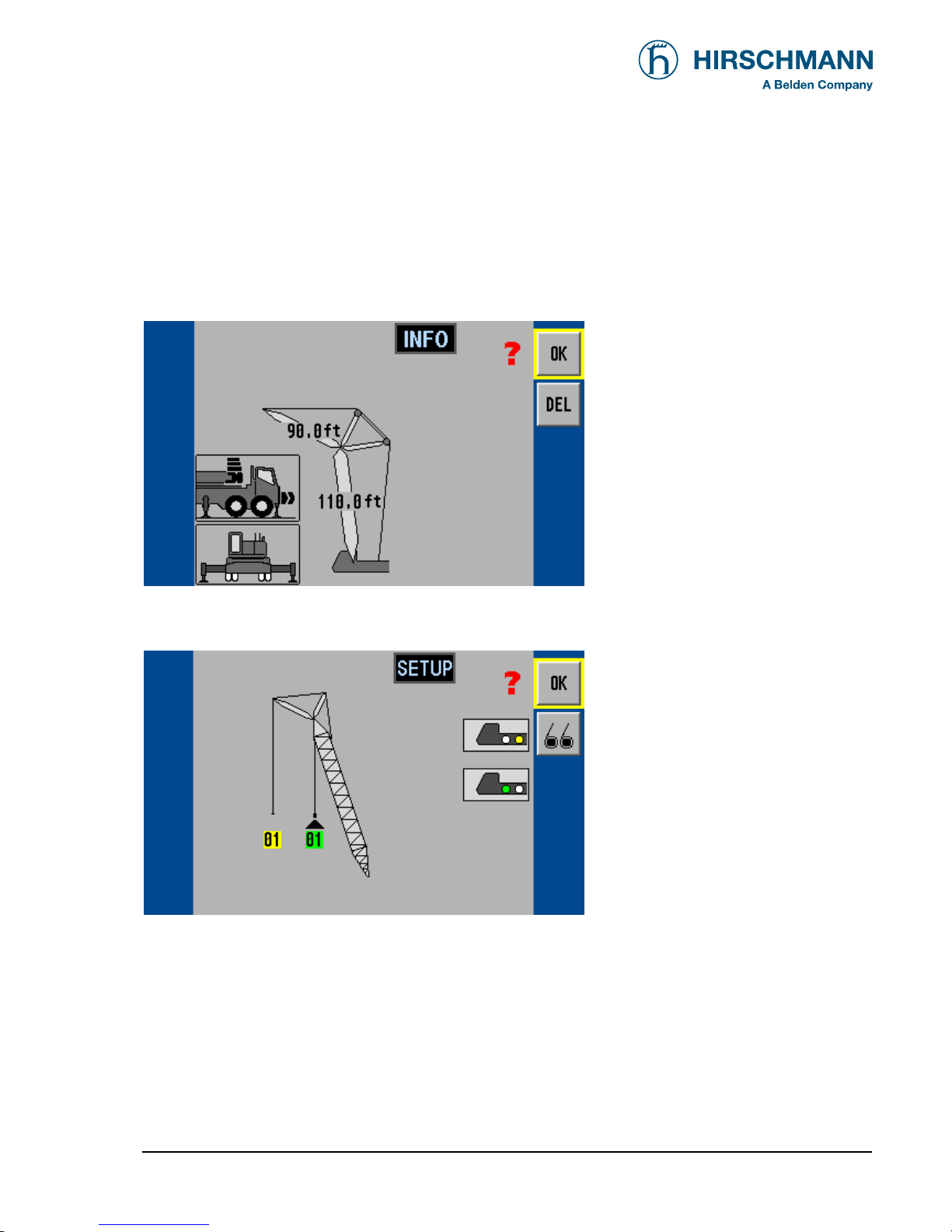
• Confirmation screens:
In this menu screens, the operator is prompted to confirm the previous made entries if crane configuration has not been modified since last turning off the system.
Check the displayed values before confirming them!
< OK, if all entries are correct
< DELETE entries, renew setup
< Quick change hoist selection
If "OK" was selected the next menu appears:
< OK, if all entries are correct
< Renew pickpoint and reeving
selection
The procedure is completed after this confirmation, and the crane menu is displayed.
Page 17
Programming
© 2008 HIRSCHMANN Automation and Control GmbH · Branch Office Ettlingen · eMail: info.ecs@hirschmann.de · www.hirschmann-usa.com 17
50 650 19 0201e_Rev C (LinkBelt278).doc / 2008-08-18 / Rev. C / rk
4.1 Interactive operating mode setup
It is necessary to setup the system by entering the respective mode of operation every time the crane
structure is modified.
The system will temporarily interrupt the movements of the crane during the programming procedure.
The correct setting is of utmost importance for the proper functioning of the system
and the crane. Therefore, only operators who are thoroughly familiar with the crane
and the operation of the system should execute the setting of the system
according to the operating configuration of the crane.
The LMI programming procedure consists of the following steps (interactive operation):
• setting the boom type configuration
• specify jib / selecting the pick point
• setting the outrigger configuration
• setting the counterweight configuration
• setting the hoist
• setting the reevings
• confirmation of the programming procedure
For easy operation, the computer guides the operator through the procedure step by step.
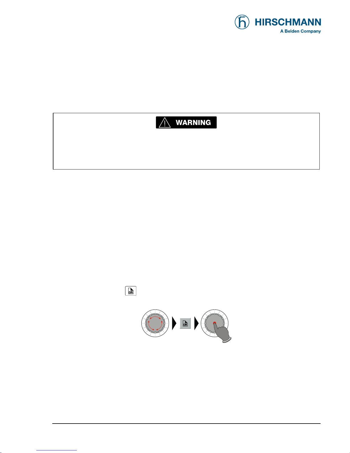
Calling up the function:
Select the soft function key
and actuate the rotary wheel button (from the LMI screen)
Page 18
Programming
© 2008 HIRSCHMANN Automation and Control GmbH · Branch Office Ettlingen · eMail: info.ecs@hirschmann.de · www.hirschmann-usa.com 18
50 650 19 0201e_Rev C (LinkBelt278).doc / 2008-08-18 / Rev. C / rk
< Start operation mode setup
The following illustrations define the symbols appearing on the display during the setup procedure.
Not all symbols will be shown, depending on the crane type and the answers to the questions.
• Setting boom type configuration
If "DEL " was selected:
select boom type with the rotary
wheel and click wheel to confirm
main
boom
tip exten-
sion
hammer-
head
hammerhead
tip extension
jib luffer luffer +fixed jib
Page 19

Programming
© 2008 HIRSCHMANN Automation and Control GmbH · Branch Office Ettlingen · eMail: info.ecs@hirschmann.de · www.hirschmann-usa.com 19
50 650 19 0201e_Rev C (LinkBelt278).doc / 2008-08-18 / Rev. C / rk
• Setting outrigger type
select base with the rotary wheel
and click wheel to confirm
• Setting counterweight configuration
select counterweight with the rotary
wheel and click wheel to confirm
or:
select counterweight with the rotary
wheel and click wheel to confirm
Page 20

Programming
© 2008 HIRSCHMANN Automation and Control GmbH · Branch Office Ettlingen · eMail: info.ecs@hirschmann.de · www.hirschmann-usa.com 20
50 650 19 0201e_Rev C (LinkBelt278).doc / 2008-08-18 / Rev. C / rk
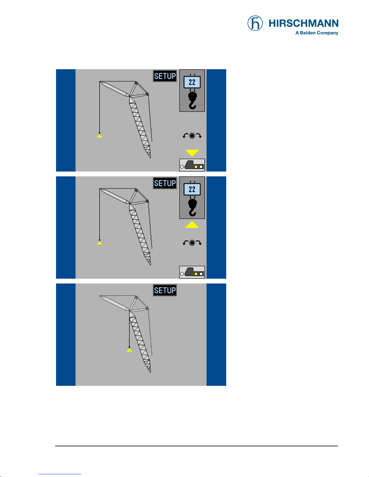
• Specify boom / Setting the hoist configuration and reevings (example luffer)
Luffing Jib length selection:
select luffer length with the rotary
wheel and click wheel to confirm
Luffing Boom length selection:
select luffer length with the rotary
wheel and click wheel to confirm
select first pick point to configure:
select pick point with the rotary
wheel and click wheel to confirm
Page 21
Programming
© 2008 HIRSCHMANN Automation and Control GmbH · Branch Office Ettlingen · eMail: info.ecs@hirschmann.de · www.hirschmann-usa.com 21
50 650 19 0201e_Rev C (LinkBelt278).doc / 2008-08-18 / Rev. C / rk
Select hoist for first pick point:
select hoist with the rotary wheel
and click wheel to confirm
Select reeving for first pick point:
select number of reevings with the
rotary wheel and click to confirm
select second pick point to configure:
select pick point with the rotary
wheel and click wheel to confirm
Page 22

Programming
© 2008 HIRSCHMANN Automation and Control GmbH · Branch Office Ettlingen · eMail: info.ecs@hirschmann.de · www.hirschmann-usa.com 22
50 650 19 0201e_Rev C (LinkBelt278).doc / 2008-08-18 / Rev. C / rk
Select hoist for second pick
point:
select hoist with the rotary wheel
and click wheel to confirm
Select reeving for second pick
point:
select number of reevings with the
rotary wheel and click to confirm
• Select hoist in use (example luffer)
< OK, to confirm
the crane menu is displayed
< mark first pick point to use
(as defined above)
< use second pick point to use
(as defined above)
active pick point is marked with a
flashing symbol
Page 23

Programming
© 2008 HIRSCHMANN Automation and Control GmbH · Branch Office Ettlingen · eMail: info.ecs@hirschmann.de · www.hirschmann-usa.com 23
50 650 19 0201e_Rev C (LinkBelt278).doc / 2008-08-18 / Rev. C / rk
4.2 Quick hoist in use selection
If, during the crane operation, the crane is switched over from front to rear hoist, the LMI system has to be adjusted to this modification. This modification can be entered without having to go through the whole LMI setup
procedure again:
Calling up the function:
By selecting the the soft function key
and actuating the rotary wheel button (from the LMI
screen)
Start of configuration setup menu:
< Start operation mode setup
DELETE entries, renew setup
< Quick change hoist
OK, if all entries are correct
Page 24

Programming
© 2008 HIRSCHMANN Automation and Control GmbH · Branch Office Ettlingen · eMail: info.ecs@hirschmann.de · www.hirschmann-usa.com 24
50 650 19 0201e_Rev C (LinkBelt278).doc / 2008-08-18 / Rev. C / rk
< OK, to confirm
the crane menu is displayed
< mark first pick point to use
(as defined above)
< use second pick point to use
(as defined above)
active pick point is marked with a
flashing symbol
Page 25

Programming
© 2008 HIRSCHMANN Automation and Control GmbH · Branch Office Ettlingen · eMail: info.ecs@hirschmann.de · www.hirschmann-usa.com 25
50 650 19 0201e_Rev C (LinkBelt278).doc / 2008-08-18 / Rev. C / rk
4.3 Programming geometrical limits
The LMI system comprises programmed limit entries for the operating range of the crane. Programming is facilitated by interactive step-by-step guidance.
• The functions can be used individually or combined. Symbols will mark active limitations.
• If a programmed limit is exceeded, the system shuts off the crane function and triggers a visual
indication (blinking symbol) and an acoustical signal.
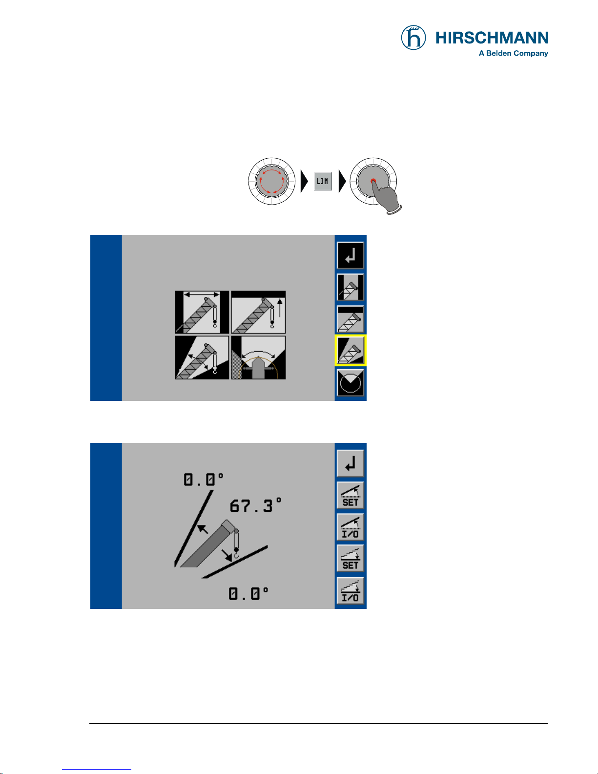
Calling up the function:
Start of limits setup menu:
< Start limits menu
back to normal LMI working screen
edit radius limit
chapter:
> 4.3.1
edit height limit
> 4.3.2
edit main boom angle limit
> 4.3.3
edit slewing angle limit /
virtual wall
> 4.3.4
Page 26

Programming
© 2008 HIRSCHMANN Automation and Control GmbH · Branch Office Ettlingen · eMail: info.ecs@hirschmann.de · www.hirschmann-usa.com 26
50 650 19 0201e_Rev C (LinkBelt278).doc / 2008-08-18 / Rev. C / rk
4.3.1 Radius Limitation
Programmable function to limit the minimum and/or the maximum boom radius
Calling up the function:
back to normal LMI working screen
edit radius limit
edit tip height limit
edit main boom angle limit
edit slewing angle limit / virtual wall
Example: Programming of the minimum radius limit. Programming of the maximum radius limit is comparable.
back to limits main menu
store actual boom position
as minimum radius limit
switch minimum radius limit on/off
store actual boom position
as maximum radius limit
switch maximum radius limit on/off
>>
Page 27

Programming
© 2008 HIRSCHMANN Automation and Control GmbH · Branch Office Ettlingen · eMail: info.ecs@hirschmann.de · www.hirschmann-usa.com 27
50 650 19 0201e_Rev C (LinkBelt278).doc / 2008-08-18 / Rev. C / rk
back to limits main menu
store actual boom position
as minimum radius limit
switch minimum radius limit
on/off
store actual boom position
as maximum radius limit
switch maximum radius limit on/off
After limitation is switched on, the limit value and the respective status symbol appears. The symbol will blink, if
one limit value is reached or exceeded:
back to limits main menu
store actual boom position
as minimum radius limit
switch minimum radius limit on/off
store actual boom position
as maximum radius limit
switch maximum radius limit on/off
Page 28

Programming
© 2008 HIRSCHMANN Automation and Control GmbH · Branch Office Ettlingen · eMail: info.ecs@hirschmann.de · www.hirschmann-usa.com 28
50 650 19 0201e_Rev C (LinkBelt278).doc / 2008-08-18 / Rev. C / rk
4.3.2 Tip Height Limitation
Programmable function for the limitation of the tip height
Calling up the function:
back to normal LMI working screen
edit radius limit
edit tip height limit
edit main boom angle limit
edit slewing angle limit / virtual wall
back to limits main menu
switch left limit on/off
store actual boom tip height
as maximum height limit
>>
Page 29

Programming
© 2008 HIRSCHMANN Automation and Control GmbH · Branch Office Ettlingen · eMail: info.ecs@hirschmann.de · www.hirschmann-usa.com 29
50 650 19 0201e_Rev C (LinkBelt278).doc / 2008-08-18 / Rev. C / rk
back to limits main menu
switch height limit on/off
store actual boom tip height
as maximum height limit
After limitation is switched on, the limit value and the respective status symbol appears.
The symbol will blink, if one limit value is reached or exceeded:
back to limits main menu
Switch height limit on/off
store actual boom tip height
as maximum height limit
Page 30
Programming
© 2008 HIRSCHMANN Automation and Control GmbH · Branch Office Ettlingen · eMail: info.ecs@hirschmann.de · www.hirschmann-usa.com 30
50 650 19 0201e_Rev C (LinkBelt278).doc / 2008-08-18 / Rev. C / rk
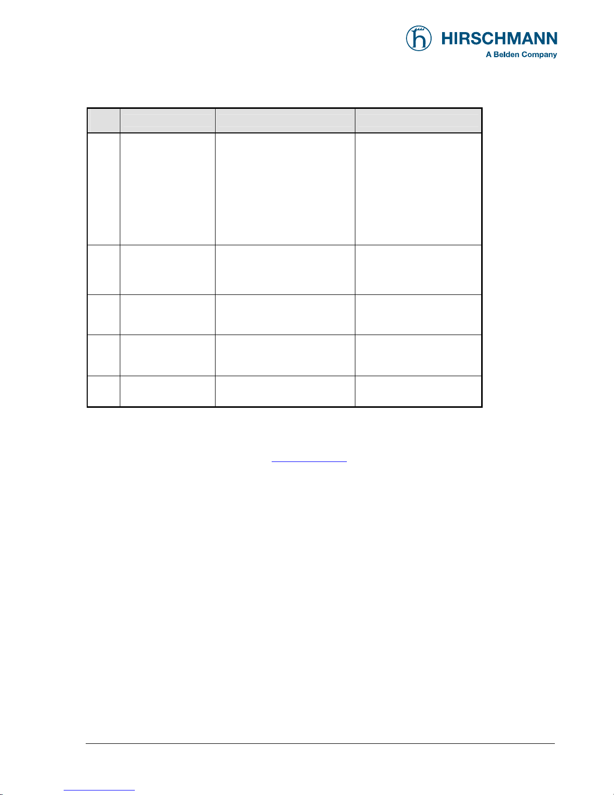
4.3.3 Boom Angle Limitation
Programmable function to limit the minimum and/or the maximum boom angle.
Calling up the function:
back to normal LMI working screen
edit radius limit
edit tip height limit
edit main boom angle limit
edit slewing angle limit / virtual wall
Example: Programming of the minimum boom angle limit. Programming of the maximum boom angle limit is
comparable.
back to limits main menu
store actual boom position
as maximum boom angle limit
switch maximum angle limit on/off
store actual boom position
as minimum boom angle limit
switch minimum angle limit on/off
Note: The 0.0°value displayed indicates a maximum and/or minimum limit has not been programmed.
Page 31

Programming
© 2008 HIRSCHMANN Automation and Control GmbH · Branch Office Ettlingen · eMail: info.ecs@hirschmann.de · www.hirschmann-usa.com 31
50 650 19 0201e_Rev C (LinkBelt278).doc / 2008-08-18 / Rev. C / rk
back to limits main menu
store actual boom position
as maximum boom angle limit
switch maximum angle limit on/off
store actual boom position
as minimum boom angle limit
switch minimum angle limit on/off
After limitation is switched on, the limit value and the respective status symbol appears.
The symbol will blink, if one limit value is reached or exceeded.
back to limits main menu
store actual boom position
as maximum boom angle limit
switch maximum angle limit on/off
store actual boom position
as minimum boom angle limit
switch minimum angle limit on/off
Page 32

Programming
© 2008 HIRSCHMANN Automation and Control GmbH · Branch Office Ettlingen · eMail: info.ecs@hirschmann.de · www.hirschmann-usa.com 32
50 650 19 0201e_Rev C (LinkBelt278).doc / 2008-08-18 / Rev. C / rk
4.3.4 Slewing Angle Limitation / Virtual Wall Definition (if equipped)
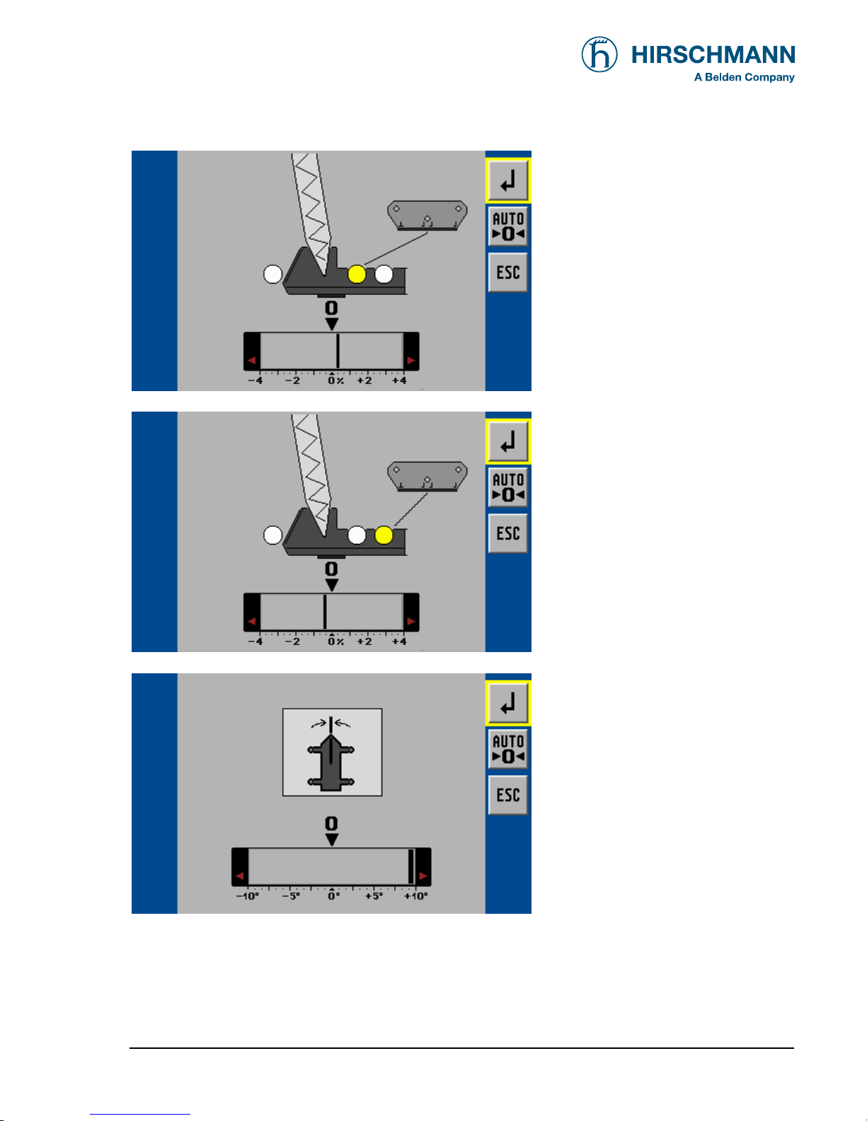
4.3.4.1 Slewing Angle Limitation
Programmable function for the limitation of the left and/or right slewing angle.
Calling up the function:
back to normal LMI working screen
edit radius limit
edit tip height limit
edit main boom angle limit
edit slewing angle limit /
virtual wall
back to limits main menu
edit slewing angle limit
edit virtual walls
>>
Page 33

Programming
© 2008 HIRSCHMANN Automation and Control GmbH · Branch Office Ettlingen · eMail: info.ecs@hirschmann.de · www.hirschmann-usa.com 33
50 650 19 0201e_Rev C (LinkBelt278).doc / 2008-08-18 / Rev. C / rk
Example: Programming of the left slewing angle limit.
Programming of the right slewing angle limit is comparable.
back to limits main menu
store actual boom position
as left slewing angle limit
switch left limit on/off
store actual boom position
as right slewing angle limit
switch right limit on/off
back to limits main menu
store actual boom position
as left slewing angle limit
switch left limit on/off
store actual boom position
as right slewing angle limit
switch right limit on/off
When limitation is switched on, the limit value and the respective status symbol appears. The symbol will blink,
if one limit value is reached or exceeded.
back to limits main menu
store actual boom position
as left slewing angle limit
switch left limit on/off
store actual boom position
as right slewing angle limit
switch right limit on/off
Page 34

Programming
© 2008 HIRSCHMANN Automation and Control GmbH · Branch Office Ettlingen · eMail: info.ecs@hirschmann.de · www.hirschmann-usa.com 34
50 650 19 0201e_Rev C (LinkBelt278).doc / 2008-08-18 / Rev. C / rk
4.3.4.2 Working Area Limitation - Virtual Wall (if equipped)
Programmable function for the limitation of the working area by up to 5 virtual walls.
The work area definition system helps the operator to define the crane’s working area. This is done by creating
vertical wall(s) that can represent obstacles (i.e. buildings, towers, poles, etc.) in the crane’s working range. The
wall(s) are set by defining points with the boom tip along the outer limits of the operator’s work area, see setup
procedure below. Because these walls are defined by the operator and are not “actual real” walls, we refer to
them as “virtual” walls. When setting the walls, always keep a safe working distance to any obstacles. Never
work outside a safe working area as outlined by common practice, standards, and manuals.
A virtual wall is set by defining two points.
To prevent inaccuracies when defining the two points for the virtual wall, use the following two rules:
1. The two points should be the same distance from the obstacle.
2. Set the two points at the maximum distance apart, which can be safely reached by the boom tip.
The operator can setup up to 5 virtual walls, the first wall is defined by a straight line between two set points.
The second through fifth walls are created by one new point and the previously selected point. After the walls
have been set, the system alerts the operator when the boom approaches them. This is done both visual and
audible. Similarly, the “virtual wall” symbol in the main screen blinks.
Calling up the function:
back to normal LMI working screen
edit radius limit
edit tip height limit
edit main boom angle limit
edit slewing angle limit /
virtual wall
>>
Page 35

Programming
© 2008 HIRSCHMANN Automation and Control GmbH · Branch Office Ettlingen · eMail: info.ecs@hirschmann.de · www.hirschmann-usa.com 35
50 650 19 0201e_Rev C (LinkBelt278).doc / 2008-08-18 / Rev. C / rk
back to limits main menu
edit slewing angle limit
edit virtual walls
back to previous menu
set a point in the working area to
start a wall
having pressed SET, the point is marked by" X"
delete existing walls
back to previous menu
move the boom tip to another point
set the second point in the
working area to create a wall
delete existing walls
When second point of the virtual wall is set, the wall is displaed and the respective status symbol appears.
The symbol will blink, if the virtual wall is reached or exceeded.
>>
Page 36

Programming
© 2008 HIRSCHMANN Automation and Control GmbH · Branch Office Ettlingen · eMail: info.ecs@hirschmann.de · www.hirschmann-usa.com 36
50 650 19 0201e_Rev C (LinkBelt278).doc / 2008-08-18 / Rev. C / rk
back to main limit menu
allows for further walls to be
added (up to 5 virtual walls)
delete all existing walls
Example with 4 virtual walls:
back to main limit menu
allows for further walls to be
added (up to 5 virtual walls)
delete all existing walls
Page 37

Inspection checks before going into operation
© 2008 HIRSCHMANN Automation and Control GmbH · Branch Office Ettlingen · eMail: info.ecs@hirschmann.de · www.hirschmann-usa.com 37
50 650 19 0201e_Rev C (LinkBelt278).doc / 2008-08-18 / Rev. C / rk
5. PRE-OPERATIONAL INSPECTION
Prior to operating the crane, the following electrical connections must be checked to ensure that
the LMI system is properly connected for the crane configuration.
• Cranes with only a main hoist
If the crane works only with the boom and without boom extension or lattice extension, no additional connections are necessary. It must however be ensured that the lifting limit switch weight is correctly mounted
on the main boom hoist rope. With even numbers of rope lines, the lifting limit switch weight shall be attached to the "dead end" of the hoist rope. With odd numbers of rope lines, the lifting limit switch weight
shall be attached to the rope line with the lowest operating speed.
If the crane works with a main boom extension or top section, the connecting cable must be mounted
between the distributor socket on the lattice extension and the distributor socket on the main boom. The
weight of the hoist limit switch of the main boom must be disconnected and mounted on the hoist limit
switch of the extension or of the jib.
Failure to reposition the hoist limit switch weight will prevent the hoist limit switch
system from functioning properly. No weight shall be mounted on the hoist limit switch
of the main boom when working with the extension/top section.
• Machines with Main and Auxiliary Hoists
If the main boom extension or the top section is not used, then the bridging plug must be plugged into the
distributor socket on the main boom and the lifting limit switch weight must be mounted on the main boom.
If the crane works with a main boom extension and/or with a lattice extension, then the connecting cable
must be mounted between the distributor socket on the extension or on the top section and the distributor
socket on the main boom. In addition, weights must be fitted to both the hoist limit switch of the main
boom and the extension or the top section.
If the boom extension or the lattice extension are in working position and if the main boom is not equipped
with a hoist rope, then the weight of the hoist limit switch on the main boom must be removed in order to
prevent endangerment to personnel or damage to the equipment.
After the electrical connections have been checked to ensure that the system is properly connected for
the respective crane configuration, the following checks must be made:
1. Check the electrical wiring connecting the various parts of the system for physical damage.
2. Check the hoist limit switches and hoist limit weights for free movement.
3. Inspection of the spring cable drum for smooth running, initial drum tension and correct winding of the
cable.
4. Inspection of the mechanical and electrical installation of power measurement sockets on the lattice
extensions (if present).
Page 38

Inspection checks before going into operation
© 2008 HIRSCHMANN Automation and Control GmbH · Branch Office Ettlingen · eMail: info.ecs@hirschmann.de · www.hirschmann-usa.com 38
50 650 19 0201e_Rev C (LinkBelt278).doc / 2008-08-18 / Rev. C / rk
The following tests must be performed with care in order to avoid damage to the crane
or injury to personnel. Proper functioning of the LMI system requires successful completion of these tests before commencing work. If the operator cannot see the hook
block approaching the head machinery, he must assign this task to an assistant
(slinger). The crane operator must be prepared to stop the crane at once in the event
that the LMI system is not working correctly, i.e. when the red warning lights fail to
light up, the acoustic alarm does not sound and the crane movements such as raising,
extending and luffing are not switched off.
Check the Hoist limit switch warning light and the acoustic alarm as follows:
1. Manually raise the weight fitted on the hoist limit switch. As soon as the weight is raised, the acoustic
alarm should sound and the hoist limit switch warning light should light up.
If the warning light and the audible alarm do not function as described and the crane
movements are not switched off, then the system is not working properly. The malfunction must be corrected before commencing work.
5. If the crane is equipped with a main boom extension or with a lattice extension, then the inspection
procedure must be repeated for the hoist limit switch of the extension/top section.
6. Check that the display of the main boom length agrees with the actual boom length.
7. Check that the display of the main boom angle agrees with the actual boom angle.
8. Check that the display of the operating radius of the crane agrees with the actual radius.
9. Check the load display by lifting a load of known weight. The accuracy of the load display must be
within the tolerance range.
Page 39

Inspection checks before going into operation
© 2008 HIRSCHMANN Automation and Control GmbH · Branch Office Ettlingen · eMail: info.ecs@hirschmann.de · www.hirschmann-usa.com 39
50 650 19 0201e_Rev C (LinkBelt278).doc / 2008-08-18 / Rev. C / rk
5.1 OPERATION
The LMI is operational once it has been adjusted properly. The crane operator must for that reason be familiar with all of the operating elements of the LMI and must make the correct entries
before the crane begins work. The proper function of the system shall be checked by lifting a
load of known weight and comparing the load to the information displayed on the LMI.
Rated loads include the weight of the hook block, slings, and auxiliary load handling devices.
This combined weight must be subtracted from the values contained in the load capacity chart in
order to determine the net load to be raised.
If any of the displays reflect a deviation between displayed and actual values an authorized PAT service representative shall be called for repair of the system or reverification of the crane's LMI calibration.
Contact: www.hirschmann-usa.com
Any structural modifications or changes to the crane shall require re-verification of the
crane's LMI calibration.
Page 40

Service and Maintenance
© 2008 HIRSCHMANN Automation and Control GmbH · Branch Office Ettlingen · eMail: info.ecs@hirschmann.de · www.hirschmann-usa.com 40
50 650 19 0201e_Rev C (LinkBelt278).doc / 2008-08-18 / Rev. C / rk
6. SERVICE AND MAINTENANCE
Daily maintenance of the load moment limitation system consists of inspecting:
1. The electrical wiring connecting the various parts of the system.
If a cable is damaged, then it must be replaced immediately.
2. The insulation of the length indicator rope and/or hoist limit switch cable and of the
cable guides. If the insulation or the cable guides are damaged, then these parts should be replaced
immediately.
3. Checking the hoist limit switches for ease of movement.
Personnel who are not specially trained may correct only those malfunctions listed in
the Malfunction Table, but they are not permitted to replace any defective mechanical
or electrical parts or cables.
Page 41

Service and Maintenance
© 2008 HIRSCHMANN Automation and Control GmbH · Branch Office Ettlingen · eMail: info.ecs@hirschmann.de · www.hirschmann-usa.com 41
50 650 19 0201e_Rev C (LinkBelt278).doc / 2008-08-18 / Rev. C / rk
6.1 Info / Service Menus
The system contains different menus in which system information are displayed.
In addition, adjustments can also be made in several Service Menus that have an effect on system behavior. Access to these menus is protected by an access code.
The system will temporarily interrupt the functions of the crane during the call-up procedure. In addition, the warning lights (3), (4)
and (5) will light up.
▼ LMI main screen (1st level of function keys)
< to Info screen LMI
< switch to 2nd level
▼ Info screen LMI
< return to main menu
Page 42

Service and Maintenance
© 2008 HIRSCHMANN Automation and Control GmbH · Branch Office Ettlingen · eMail: info.ecs@hirschmann.de · www.hirschmann-usa.com 42
50 650 19 0201e_Rev C (LinkBelt278).doc / 2008-08-18 / Rev. C / rk
▼ LMI main screen (2nd level of function keys)
< back to previous menu
< to LMI value screen
< to service menus
< to CAN-bus menu
▼ LMI value screen
< back to previous menu
▼ Service menu (main screen)
< back to previous menu
< to System Info node 2
(iFLEX5 central unit)
< to calibration menu
(access code required)
Page 43

Service and Maintenance
© 2008 HIRSCHMANN Automation and Control GmbH · Branch Office Ettlingen · eMail: info.ecs@hirschmann.de · www.hirschmann-usa.com 43
50 650 19 0201e_Rev C (LinkBelt278).doc / 2008-08-18 / Rev. C / rk
▼ System Info node 2 (digital inputs)
< back to previous menu
< to info screen digital outputs
< to info screen analog inputs
▼ System Info node 2 (digital outputs)
< back to previous menu
< to info screen digital inputs
< to info screen analog inputs
▼ System Info node 2 (analog inputs)
< back to previous menu
< to info screen digital inputs
< to info screen digital outputs
Page 44

Service and Maintenance
© 2008 HIRSCHMANN Automation and Control GmbH · Branch Office Ettlingen · eMail: info.ecs@hirschmann.de · www.hirschmann-usa.com 44
50 650 19 0201e_Rev C (LinkBelt278).doc / 2008-08-18 / Rev. C / rk
▼ CAN-bus menu
< back to previous menu
< to CAN symbol legend
▼ CAN symbol legend
< back to previous menu
Page 45

Troubleshooting
© 2008 HIRSCHMANN Automation and Control GmbH · Branch Office Ettlingen · eMail: info.ecs@hirschmann.de · www.hirschmann-usa.com 45
50 650 19 0201e_Rev C (LinkBelt278).doc / 2008-08-18 / Rev. C / rk
7. TROUBLESHOOTING
7.1 General
In the event of a malfunction or an operating error recognized by the system,
codes will be displayed in the status field of the Data display (1) which specify
the reason for the malfunction:
Error in the LMI system:
Error in the control system:
or
The error codes listed in the following Malfunction Table will identify various
faults which can occur with this system. Malfunctions in the LMI System which
were caused by exceeding the prescribed ranges or by operating errors on the
part of the crane operator can normally be corrected by the crane operator him-
self. Errors in the microprocessor system may only be corrected by factory-
trained Customer Service personnel.
Contact Hirschmann Customer Service or local dealer if this occurs.
Internet Support:
www.hirschmann-usa.com
> ELECTRONIC CONTROL SYSTEMS > Service &
Support
Page 46

Troubleshooting
© 2008 HIRSCHMANN Automation and Control GmbH · Branch Office Ettlingen · eMail: info.ecs@hirschmann.de · www.hirschmann-usa.com 46
50 650 19 0201e_Rev C (LinkBelt278).doc / 2008-08-18 / Rev. C / rk
7.2 LMI System Malfunction Table (LMLG V 1.x)
Fault
code
Error Cause Elimination
E01
Lowered below radius
range or angle range
exceeded
• Fallen below the minimum
radius or gone past the maximum angle specified in the respective load chart due to raising the boom too far
• Lower the boom to a radius or angle specified in
the load chart.
E02
Radius range exceeded or lowered
below angle range
• Gone past the maximum radius
or lowered below the minimum
angle specified in the respective load chart due to lowering
the boom too far
• Raise the boom to a radius
or angle specified in the
load chart.
• A non existing operating mode
has been selected
• Set the correct operating
mode for the operating state
in question
• The boom is in a non-permitted
slewing zone
• Slew the boom to a permitted area.
E04
Operating mode not
acknowledged or non
permitted slewing zone
• The selected operating mode is
not available in the FlashEPROM or blocked
• Check the Data software in
the Flash-EPROM
• A non existing main boom
length has been selected
• Set the correct main boom
length for the operating
state in question
E05
Main boom length not
available
• The selected main boom length
is not available in the FlashEPROM or blocked
• Check the Data software in
the Flash-EPROM
E06
Radius range exceeded or lowered
below angle range with
luffing jib operation
• Maximum radius as specified in
the load chart exceeded or lowered below minimum angle due
to lowering the luffing jib too far
• Raise the jib to a radius or
angle specified in the load
chart.
E07
Overload relays check
• Relays = overload active and
CU input 20 = on
• Relays = no overload and CU
input 20 = off
• Check cable to overload
relays and CU input 20
• Check relays
• Check CU input 20
• Cable between the central unit
and the force transducer defective or loose. Water inside the
plug of the transducer
• Force transducer defective
• Check cable as well as
plugs, replace, if need be
• Replace force transducer
E14
Below lower limit value
in measuring channel
"force main boom right"
• Electronic component in the
measuring channel is defective.
• Replace sensor unit
• Cable between the central unit
and the angle sensor defective
or loose. Water inside the plug
of the angle sensor
• Angle potentiometer defective
• Check cable as well as
plugs, replace, if need be.
• Replace angle sensor
E15
Below lower limit value
in measuring channel
"angle main boom"
• Electronic component in the
measuring channel defective.
• Replace sensor unit
E16
Below lower limit value
in measuring channel
"angle luffing jib"
• Refer to E15
• Refer to E15
E17
Below lower limit value
in measuring channel
"force luffing jib left"
• Refer to E14 • Refer to E14
Page 47

Troubleshooting
© 2008 HIRSCHMANN Automation and Control GmbH · Branch Office Ettlingen · eMail: info.ecs@hirschmann.de · www.hirschmann-usa.com 47
50 650 19 0201e_Rev C (LinkBelt278).doc / 2008-08-18 / Rev. C / rk
Fault
code
Error Cause Elimination
• Cable between the central unit
and the slewing angle sensor
defective or loose. Water inside
the plug of the angle sensor
• Check cable as well as
plugs, replace, if need be.
• Slewing angle potentiometer is
defective
• Replace slewing angle
sensor
E1A
Below lower limit value
in measuring channel
"slewing angle 1".
• Electronic component in the
measuring channel defective
• Replace sensor unit
E1B
Below lower limit value
in measuring channel
"slewing angle 2"
• Refer to E1A
• Refer to E1A
E1C
Below lower limit value
in measuring channel
"angle main boom tip"
(if avail.)
• Refer to E15 • Refer to E15
E1E
Below lower limit value
in measuring channel
"force derricking system"
• Refer to E14 • Refer to E14
E1F
Below lower limit value
in measuring channel
"SL mast angle" (if
avail.)
• Refer to E15 • Refer to E15
E24
Upper limit value in
measuring channel
"force main boom left"
has been exceeded.
• Refer to E14
• Refer to E14
E25
Upper limit value in
measuring channel
"main boom angle" has
been exceeded.
• Refer to E15
• Refer to E15
E26
Upper limit value in
measuring channel
"luffing jib angle" has
been exceeded.
• Refer to E15
• Refer to E15
E27
Upper limit value in
measuring channel
"force luffing jib left"
has been exceeded.
• Refer to E14
• Refer to E14
E2A
Upper limit value in
measuring channel
"slewing angle 1" has
been exceeded
• Refer to E1A
• Refer to E1A
E2B
Upper limit value in
measuring channel
"slewing angle 2" has
been exceeded
• Refer to E1A
• Refer to E1A
E2C
Upper limit value in
measuring channel
"main boom tip angle"
has been exceeded (if
avail.).
• Refer to E15
• Refer to E15
Page 48

Troubleshooting
© 2008 HIRSCHMANN Automation and Control GmbH · Branch Office Ettlingen · eMail: info.ecs@hirschmann.de · www.hirschmann-usa.com 48
50 650 19 0201e_Rev C (LinkBelt278).doc / 2008-08-18 / Rev. C / rk
Fault
code
Error Cause Elimination
E2E
Upper limit value in
measuring channel
"force derricking system" has been exceeded.
• Refer to E14
• Refer to E14
E2F
Upper limit value in
measuring channel "SL
mast angle" has been
exceeded.
• Refer to E14
• Refer to E14
E37
Error in the logical
program flow
• System program file is defec-
tive
• Flash-EPROM defective
• Upload valid system soft-
ware
• Replace central unit
E38
System program and
crane data file do not
match.
• The system program in the LMI
does not match to the programming in the crane data file
• Upload valid system program file or the valid crane
data file
E39
System program and
load chart file do not
match
• The system program in the LMI
and the programming in the
load chart file do not match.
• Upload valid system program file or the valid load
chart file
E3A
crane data file and load
chart file do not match
• Crane type in dat file and load
chart file is different
• Change dat file and/or load
chart file
E43
Error in the write/read
memory, (RAM)
• Write/read memory (RAM) or
central unit defective.
• Replace central unit
E51
Error in the crane data
file
• No valid data in the crane data
file.
• Flash-EPROM defective
• Upload valid crane data file
• Replace central unit
E52
Error in load chart file.
• No valid data in the load chart
file
• Flash-EPROM defective
• Upload valid load chart file
• Replace central unit
E56
Error in crane data file.
• No valid data in the crane data
file during calibration.
• Flash-EPROM defective
• Restore or upload valid
crane data file
• Replace central unit
E57
Error in serial crane
data file.
• Calibration data file does not
contain valid data.
• Flash-EPROM defective
• Upload calibration data file
• Replace central unit
• No valid data in the load chart
file
• Upload valid load chart file
• Base number not programmed • Program the correct base
number (1 for base 1, 2 for
base 2)
E60
The number of the
selected File base and
the programmed value
are not identical
• Load chart file programmed
wrong
• Check base programming in
the load chart file.
• CAN Bus cable between the
central unit and the sensor unit
defective or not connected.
• Check the connection between the central unit and
the sensor units
• Can bus port in the central unit
defective
• Replace the central unit
E61
Error in the CAN bus
data transfer for all
CAN units
• Short circuit in a CAN Bus
cable
• Replace Can Bus cable
E80
Error in the slewing
angle measurement
• The difference between the
average of the slewing angle
and one of the wipers of the
slewing potentiometer is out of
the tolerance
• Check the slewing potentiometer adjustment
• Replace slewing angle
sensor
Page 49

Troubleshooting
© 2008 HIRSCHMANN Automation and Control GmbH · Branch Office Ettlingen · eMail: info.ecs@hirschmann.de · www.hirschmann-usa.com 49
50 650 19 0201e_Rev C (LinkBelt278).doc / 2008-08-18 / Rev. C / rk
Fault
code
Error Cause Elimination
E81
Too large difference of
the boom angles at tip
and base boom (if
avail.)
• The angle as to the horizontal
on the boom head exceeds the
main boom angle by more than
5 degrees.
• Check angle sensor on the
boom head.
• Check angle sensor on the
base boom.
E82
Too large difference of
the luffing jib angles at
tip and base jib.
• The angle as to the horizontal
on the jib head exceeds the luffing jib angle by more than 5
degrees.
• Check angle sensor on the
jib head.
• Check angle sensor on the
jib base.
E83
Maximum force in the
main boom pendants
exceeded
• The force actuating on the main
boom pendants has exceeded
the programmed value
• Reduce force acting on the
main boom pendants.
E84
Wrong rigging condition.
• The selected rigging condition
is not contained in the crane
data file.
• Select another rigging condition
• Check the programming in
the crane data file.
E85
Error in the radius
determination
• The computed radius is too
small (negative deflection)
• Check the programming in
the crane data file.
E88
Faulty main boom
position during luffing
jib operation
• During luffing jib operation the
main boom is not in the prescribed angle range
• Angle measurement of main
boom defective.
• Luff boom to the permitted
range
• Check angle measurement
of the main boom.
E89
Faulty positioning of
the jib during operation
with fixed angle to the
main boom or to a
luffing jib
• During operation with fixed jib
to the main boom, the jib is not
in the permitted angle range
• Angle measurement of the jib
defective
• Luff the auxiliary jib to the
permitted range
• Verify angle measurement
of the auxiliary jib.
E98
LMI watchdog activated
• LMI processing time limit
exceeded
• Reset system
• Connect PC terminal
and watch error messages
EAB
Short circuit in the A2B
switch circuit
• Short circuit in the A2B
switch
• Short circuit in the cable to
the A2B switch
• Replace A2B switch
• Replace cable to the
A2B switch
EAC
A2B switch circuit
disconnected
• Disconnected cable in the
A2B switch
• Disconnected cable to the
A2B switch
• Connect or replace cable in the A2B switch
• Connect or replace cable to the A2B switch
EAD
No valid A2B switch
status
• Sensor wrong function
• CAN bus delay
• Replace A2B switch
• Replace cable to the
A2B switch
Page 50
Troubleshooting
© 2008 HIRSCHMANN Automation and Control GmbH · Branch Office Ettlingen · eMail: info.ecs@hirschmann.de · www.hirschmann-usa.com 50
50 650 19 0201e_Rev C (LinkBelt278).doc / 2008-08-18 / Rev. C / rk
Fault
code
Error Cause Elimination
EB1
Below lower limit value
in measuring channel
"rope length on the
winch”
• No rope on the winch
(* only EB1)
• No sensor for winch measuring
available
• rope length not calibrated
• wrong rope/winch parameters
in data-programming
• counter input not define in configuration
• counter input defective
• calibrate rope length
• mount sensor or turn off this
function in the dataprogramming
• calibrate rope length, layer
• check parameter in the
data-programming
• change I/O configuration
• change Iflex
EB2
Upper limit value in
measuring channel "
rope length on the
winch" has been exceeded.
• Rope completely rolled up on
winch (* only EB2)
• Refer to EB1
• calibrate rope length
• Refer to EB1
EB3
Upper limit value in
measuring channel
"hook height" has been
exceeded.
• No rope length between front
sheave and hook
• Refer to EB1
• Refer to EB1
EDD
Battery empty
• Battery check detected a low
voltage of the battery
• change and setup battery
• Temporary: Press alarm off
button to work without datalogger
EFD
LMI Watchdog extra
time
• Function requires more than 0.5
seconds to activate, e.g.
write flash PROM
• Message is deactivated
automatically after processing
Note:
If a fault message is displayed that is not included in the present list, then please contact
your local Hirschmann Customer Service. > www.hirschmann-
usa.com <
Page 51

Appendix: Menu overview calibration menus
© 2008 HIRSCHMANN Automation and Control GmbH · Branch Office Ettlingen · eMail: info.ecs@hirschmann.de · www.hirschmann-usa.com 51
50 650 19 0201e_Rev C (LinkBelt278).doc / 2008-08-18 / Rev. C / rk
▼ Start screen
SYSTEM START SCREEN
No function keys available.
Screen automatically changes after
completion of the system test.
▼ LMI main screen (1st level of function keys)
switch to 2nd level of function keys
▼ LMI main screen (2nd level of function keys)
back to the previous menu
to service menu
Page 52

Appendix: Menu overview calibration menus
© 2008 HIRSCHMANN Automation and Control GmbH · Branch Office Ettlingen · eMail: info.ecs@hirschmann.de · www.hirschmann-usa.com 52
50 650 19 0201e_Rev C (LinkBelt278).doc / 2008-08-18 / Rev. C / rk
▼ Service menu (start screen)
back to the previous menu
to calibration menus
(access code input)
▼ Calibration menu (start access code input)
For access to the calibration menus
it is necessary to input a matching
5-digit code.
Use the rotary selection wheel to
input a numeral, and then push the
wheel button to select the next digit.
If input is complete the confirmation
screen appears:
▼ input service code (confirmation screen)
OK, confirm selected code
▼ zero-setting force 1
Page 53
Appendix: Menu overview calibration menus
© 2008 HIRSCHMANN Automation and Control GmbH · Branch Office Ettlingen · eMail: info.ecs@hirschmann.de · www.hirschmann-usa.com 53
50 650 19 0201e_Rev C (LinkBelt278).doc / 2008-08-18 / Rev. C / rk
to next calibration step
zero-setting force 1 (SKM)
abort calibration step
▼ zero-setting force 2
to next calibration step
zero-setting force 2 (SKM)
abort calibration step
▼ zero-setting slewing angle sensor
to next calibration step
zero-setting slewing angle (DWG)
abort calibration step
Page 54

Appendix: Important notes for crane operators and crane operating companies
© 2008 HIRSCHMANN Automation and Control GmbH · Branch Office Ettlingen · eMail: info.ecs@hirschmann.de · www.hirschmann-usa.com 54
50 650 19 0201e_Rev C (LinkBelt278).doc / 2008-08-18 / Rev. C / rk
INSTRUCTIONS 1 Shut-off values for boom cranes with variable load ratings
depending on variable working radius
The crane shut-off values are determined by us based on the load charts and design drawings specified by the
crane manufacturer.
These theoretical shut-off values must be checked by means of tests on the crane with weighed test loads for
all modes and at least with the following rig arrangements, depending on the crane design.
• Cranes with fixed boom length in operation:
Smallest, medium and largest radius for shortest, medium and longest boom length, as well as shortest,
medium and longest jibs for these boom lengths.
INSTRUCTIONS 2 Important notes for the crane operator
The LMI is an operating aid to warn the crane operator of an imminent overload or of the hook block
approaching the boom head, in order to avoid possible damage to property or personal injury.
This system cannot be, and is not intended to be, a substitute for good judgement or experience on the part of
the crane operator, or for the application of recognized, safe working methods when using cranes. The crane
operator is not released from his obligation to operate the crane safely. He must ensure that he fully
understands and follows the notes and instructions displayed. Before beginning work with the crane, the crane
operator must carefully read and understand the entire Manual to ensure that he is aware of the operation of the
LMI and the crane. Proper functioning depends on due daily inspection of the system and compliance with the
operating instructions listed in this Manual.
The system can only offer the crane operator help if the LMI is correctly adjusted, and the correct load chart and
the correct operating code have been entered for the particular rig arrangement. To avoid damage to property
and serious or even fatal injuries to persons, it is essential to ensure that the LMI is correctly adjusted before
beginning crane work.
This system can be equipped with a key-operated switch which is located in the
microprocessor central unit. This key-operated switch overrides the LMI's shut-off feature.
The switch may only be actuated in emergencies by authorized personnel. Non-compliance
with these instructions may lead to damage to property and serious or even fatal injuries to
persons.
Page 55

Appendix: Important notes for crane operators and crane operating companies
© 2008 HIRSCHMANN Automation and Control GmbH · Branch Office Ettlingen · eMail: info.ecs@hirschmann.de · www.hirschmann-usa.com 55
50 650 19 0201e_Rev C (LinkBelt278).doc / 2008-08-18 / Rev. C / rk
INSTRUCTIONS 3 Notes on Electromagnetic Compatibility (EMC) in electronic
systems taking account of the effect of electromagnetic fields
Electromagnetic fields are having an increasing effect on electronic systems and may lead to malfunctions; to
avoid these, we have listed preventive measures in the following, according to the latest state of technology:
1. The preventive measures proceed primarily from the basic idea that the electronic circuits should be
shielded from irradiated high frequencies by a closed, low-resistance protective shield against highfrequency interference.
− All components are equipped with metallic outer housings with grounding option;
− only cables with a braided screen are used. The screen must generously cover all connectors and must
be of high conductivity;
− coupling of the crane earth and the electronics earth in one single point of the system only.
2. The general precautions listed under Section 1 cannot assure complete protection against electromagnetic
fields in all cases, however, since the size and type of effect depend on local conditions.
Examples of such influencing factors are:
− particularly unfavourable arrangement of the aerials in relation to the system,
− very high transmission power,
− consistent compliance with measures of Section 1 not possible due to local conditions,
− long cables,
− coupling of interference into the supply leads.
In unfavourable conditions, one has no choice but to take experimental measures on site, in addition to the
preventive measures, while taking account of the principles mentioned in Section 1, for example:
• fitting filters or short-circuiting the interference frequencies using capacitors;
• establishing or separating earth connections;
• using a guarded shield system.
Page 56

Appendix: Important notes for crane operators and crane operating companies
© 2008 HIRSCHMANN Automation and Control GmbH · Branch Office Ettlingen · eMail: info.ecs@hirschmann.de · www.hirschmann-usa.com 56
50 650 19 0201e_Rev C (LinkBelt278).doc / 2008-08-18 / Rev. C / rk
INSTRUCTIONS 4 Notes on industrial safety when repairing display and control
consoles
Caution: Liquid crystal displays contain liquid chemical substances in the display.
Particular caution and care are therefore necessary:
• when operating equipment containing liquid crystal displays
• during storage and transport (risk of breakage !)
• when disposing of unusable or excess liquid crystal displays
Possible sources of danger are chemical effects in the event of skin contact with broken
liquid crystal displays. In the event of contact, wash the affected skin areas thoroughly with
soap. Be particularly careful with open wounds !
INSTRUCTIONS 5 Installation instructions for display and control consoles without
closed metallic housing
To avoid radio interference, high-frequency devices and equipment coming under general approval
requirements published by the Federal Minister for Post and Telecommunications in his Official Gazette No.
163/1984 as Decree No. 1045/1984 and No. 1046/1984 must comply with the limit values and conditions laid
down there.
For display and control consoles without closed metallic housing (dashboard installation version), the conductor
screen must therefore be mounted on the dashboard directly in front of the console by means of a bare cable
clip.
Page 57

Revision History
© 2008 HIRSCHMANN Automation and Control GmbH · Branch Office Ettlingen · eMail: info.ecs@hirschmann.de · www.hirschmann-usa.com 57
50 650 19 0201e_Rev C (LinkBelt278).doc / 2008-08-18 / Rev. C / rk
Version Date Modifications Name
Rev. A 2008-03-04 First Issue for Link-Belt 278 LMI with iFLEX5 System rk
Rev. B 2008-04-22 Revise Manual to meet LinkBelt’s recommendations Sc
Rev. C 2008-08-18 Description for battery symbols added.
Description for confirmation screens added.
rk
 Loading...