

Page 1
Print: 1.0
Issue: October 2000
BH_8450E
IRD 8500/..
Operating manual
Integrated Receiver Decoder
Page 2

Contents
Introduction 1-1
General notes....................................1-2
Technical modifications ...........................................1-2
Copyright .....................................................1-2
Explanation of warning and note symbols ................1-2
Safety notes .....................................1-3
Explanation to digital TV broadcasting technique ..........1-4
General ......................................................1-4
Definitions ....................................................1-7
Putting into operation 2-1
Description ......................................2-2
General ......................................................2-2
Design .......................................................2-2
Power supply ..................................................2-3
Control .......................................................2-3
Monitoring ....................................................2-3
SAT-receiver/demodulator .........................................2-4
MPEG processing ...............................................2-5
Conditional Access (Option) .......................................2-6
Video processing ...............................................2-6
Audio processing ...............................................2-7
Block diagram..................................................2-8
Interfaces and operating elements .....................2-9
Front-panel....................................................2-9
Rear-panel ...................................................2-10
Start-up........................................2-13
Procedure....................................................2-13
Contents
IRD 8500/..
0 - 2 Intergrated Receiver Decoder
Page 3

Menu operation 3-1
Menu tree.......................................3-2
Menu operation...................................3-4
Operation .....................................................3-4
Change settings ................................................3-4
Alarm and warning messages ......................................3-5
Password protection .............................................3-5
Configuration / Identification .......................................3-6
Status display / history / operation log ................................3-6
Preset / Reset .................................................3-7
Network ......................................................3-7
Display.......................................................3-9
Date / Time / Temperature ........................................3-9
PIN-Code .....................................................3-9
Maintenance 4-1
Important notes...................................4-2
Functional check..................................4-3
Procedure ....................................................4-3
Nominal operation state ..........................................4-3
Help with problems ................................4-4
Change ........................................4-5
Changing the mains fuse..........................................4-5
Changing the battery.............................................4-5
Fitting of options ..................................4-7
General ......................................................4-7
Software update ..................................4-8
Handling........................................4-8
Storage ......................................................4-8
Transport .....................................................4-8
Disposal ......................................................4-8
Contents
IRD 8500/..
Intergrated Receiver Decoder 0 - 3
Page 4

Ordering information ...............................4-9
Ordering information Integrated Receiver Decoder for 230 V mains connection ..4-9
Ordering information Integrated Receiver Decoder for 115 V mains connection ..4-9
Ordering information for options .....................................4-9
Services .......................................4-10
Changes 5-1
Appendix 6-1
General data ....................................6-2
Technical data ...................................6-2
Error messages ..................................6-6
Contents
IRD 8500/..
0 - 4 Intergrated Receiver Decoder
Page 5

General notes
NOTE: Keep this manual handy at all times.
Technical modifications
Changes of information contained in this manual reserved.
Copyright
This manual contains information protected by copyright. All rights reserved. No part of
this manual may be photocopied, otherwise reproduced or translated into another
language without the prior written consent of Hirschmann.
Explanation of warning and note symbols
WARNING: Indicates that ignorance or neglicence of the recommended
cautionary measures may lead to personal injuries or
device damage.
ATTENTION: Indicates that ignorance or neglicence of the recommended
cautionary measures may lead to device damage.
NOTE: Useful tips and information on practical application.
Introduction
IRD 8500/..
1 - 2 Intergrated Receiver Decoder
Page 6

Safety notes
WARNING: Improper use of electrical devices may result in electrical shocks !
ATTENTION: The IRD 8500/.. must be connected only to grounded mains !
ATTENTION: The mains cable must not be exposed to mechanical stress !
ATTENTION: The mains cable must be disconnected from the IRD 8500/.., if:
- the cable or the plug was damaged.
- a liquid was spilled onto the device
- the cabinet was damaged
Introduction
IRD 8500/..
Intergrated Receiver Decoder 1 - 3
Page 7
Explanation to digital TV broadcasting technique
General
Objective With the help of data reduction by means of minimizing redundant moving picture in-
formation as well as flexible organisation of the signal quality, transmission capacity
shall be increased.
Realization First picture and sound data are reduced. Out of the compressed data streams a multi-
plex data stream is composed together with additional information (e.g. teletext).
The necessary methods for that are defined in the MPEG-2. For the additional information only the syntactic frame is defined here. Which kind of data and in which way
data are to be integrated into the multiplex data stream is layed down by the European
DVP-project.
For decoding a high transmission quality and an approximative zero bit error rate must
be guaranteed. For digital modulation methods QPSK and QAM channel coding is
used. Through these methods a certain amount of bit errors can be corrected on the
receiver side.
The procedures for coding and transmission are defined by the European DVP-project.
MPEG-2 The MPEG-2 standard (ISO/IEC 13818) set up by the MPEG standardization commit-
tee regulates the coding of moving pictures and the accompanying sound.
DVB In addition to the transmission procedures defined by the MPEG-2 standard, the Euro-
pean DVB-project (Digital Video Broadcasting) has layed down a number of definitions
which were forwarded to the organisations ETSI / CENELEC for standardization.
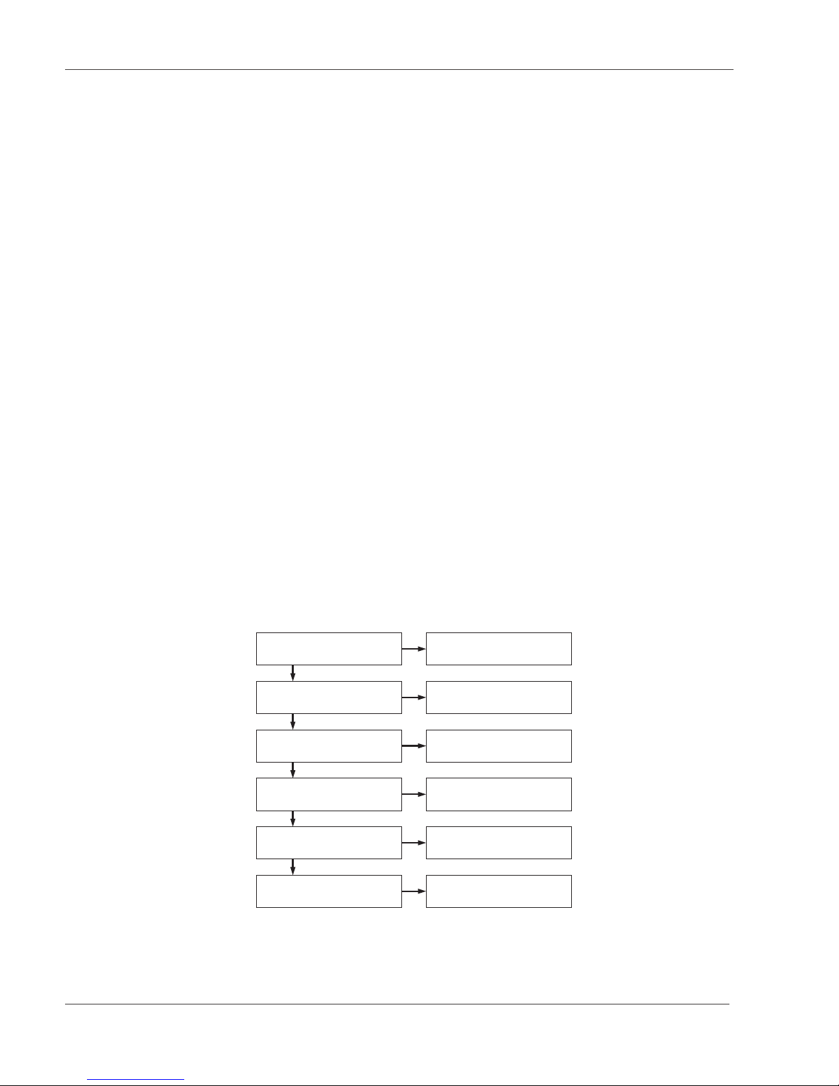
MPEG-decoding For decoding the MPEG data stream several steps are necessary.
For that different elements out of the data stream are used. ( see picture 1)
Introduction
IRD 8500/..
1 - 4 Intergrated Receiver Decoder
Transportstream Synchronisation
Reading out the Transportstream
Sync Byte 0x47
Program Specific Information
(PSI)
Selecting a program
Packet Identifikation (PID)
Decoding
Conditional Access Table (CAT)
Synchronisation Program
(VIDEO / AUDIO)
Programm Clock Reference (PCR)
Time stamps (PTS + DTS)
Decoding additional data
Service Information (SI)
Page 8

Transport stream
synchronization
The transport stream packet consists of different substream data packets. The data
packets are transmitted with a length of 188 bytes. At the beginning of each packet is
the sync-byte (0x47). Because this value is not exclusively reserved for the sync-byte,
the repetetive occurrence of the sync-byte every 188 bytes has to be checked too to
ensure stable synchronization.
Packet identifying To identify the individual packets there is a Packet Identity (PID) contained at the be-
ginning of each packet (after the sync-byte). Each substream
(e.g. video, audio) gets its own PID. Some PIDs are assigned automatically and cannot be changed. (e.g.: PAT, CAT , .. siehe table 1)
Structure of the transport
stream
Normally a transport stream contains several programs. Each of this program contains
again a number of different substreams (elementary streams).
Program access With the help of the information about the structure of a transport stream the required
program can be selected for decoding. If a program contains different equivalent elementary streams (e.g. different languages), the respective selection has to be made,
too. The selected elementary stream packets, which were detected by PID ,are passed
on from the demultiplexer to the decoder.
Decoding The encoding of the received data can take place on various levels.
The entire transport stream or elementary streams (Packetized Elementary Streams
PES ) can be encoded. The header information of the transport stream always stays
uncoded, the header information of the PES is also encoded when the entire transport
stream is encoded.
The data necessary for decoding are transmitted in the Entitlement Control Messages
(ECM) and in the Entitlement Management Messages (EMM).
The ECMs also contain the necessary keycodes and the EMMs also contain the access codes for the receiver.
Program
synchronization
A program consists of several elementary streams. To synchronize the decoding of the
individual elementary streams a common reference is necessary.
For that a Program Clock Reference (PCR) is included in each elementary stream.
This information is contained in the Adaption Field, which is also transmitted in a cycle
of max. 100ms. The Adaption Field always stays uncoded.
The information derived from the PCR-data is used to control the 27 MHz system
clock of the receiver. In this way the synchronization of multiplexer and demultiplexer
is ensured.
For syncronizing the elementary streams additional time reference values, Decoding
Time Stamps (DTS) and Presentation Time Stamps (PTS) are contained in the elementary streams.
Introduction
IRD 8500/..
Intergrated Receiver Decoder 1 - 5
Page 9

Data tables On the one hand, the tables are defined in the MPEG-2 standard and on the other
hand, they are specified from the DVB-project.
MPEG Program Specific Information (PSI):
PAT Program Association Table, contains information about the programs
in the transport stream.
PMT Program Map Table, contains information about the elementary
streams belonging to the program.
DVB Service Information (SI):
CAT Conditional Access Table, contains the necessary information for the
CA-module for decoding coded programs.
NIT Network Information Table, contains information about the included
programmes (e.g. frequency, modulation type, ...) of the distribution network
and the name of the distribution network.
SDT Service Description Table, describes the available programmes and
services of the distribution network.
EIT Event Information Table, an electronic TV-guide with identification of
programme start and age classification.
RST Running Status Table, contains status information about the individual
programmes.
TDT Time and Date Table, contains information about the current date and time
(UTC).
TOT Time Offset Table, contains information about the local date- and time-shift.
ST Stuffing Table, without content, is created when overwriting invalid tables.
BAT Bouquet Association Table, informs about the different programs of the
provider independent from the broadcasting area.
The PIDs of the tables are pre-assigned. the only exeption are the PMTs, whose PIDs
are defined in the PAT. To transmit different tables with one PID, each table contains
a Table_ID at the beginning.
Table PID Table_ID
PAT 0x0000 0x00
PMT 0x0020...0x1FFE 0x02
CAT 0x0001 0x01
NIT 0x0010 0x40...0x41
BAT 0x0011 0x4A
SDT 0x0011 0x42, 0x46
EIT 0x0012 0x4E...0x6F
RST 0x0013 0x71
TDT 0x0014 0x70
TOT 0x0014 0x73
ST 0x0010...0x0014 0x72
Introduction
IRD 8500/..
1 - 6 Intergrated Receiver Decoder
Page 10

Definitions
MPEG Moving Pictures Experts Group: A standardization committee, whose task is the enco-
ding of moving pictures and sound information. Developed the basic standards for data
reduction. ( MPEG-1... MPEG-4 )
DVB Digital Video Broadcast: For digital broadcasting of TV-signals additional standards for
transmitting of MPEG-signals were defined.
Symbol rate Data rate of the applied digital signal on the input. For correct decoding the data rate
is to be set on the receiver.
Code rate According to the selected transmission path encoding is applied to ensure correct
transmission of the data signal. The code rate corresponds to the ratio between useful
data and total amount of data. The more additional data is transmitted, the better the
original useful signal can be restored in case of a transmission failure.
BER Bit Error Rate: The BER is measured by means of the Viterbi decoder. The BER
shows the ratio between the correctly received bits and the incorrect bits. For correct
processing of moving pictures the BER should not exceed a value of 1x10
-5
.
Multiplex Several Packetized Elementary Streams (PES) are multiplexed into a transportstream
(acc. to time-multiplex for MPEG2/Packetgeneration). A single PES contains the video,
audio and data information of a single programme.
The length of the transmitted packets are 188 or 204 bytes. In order to be able to
re-assign the individual packets on the receiver side, the packets are provided with a
programme identification.
C/N Carrier to Noise: Carrier to noise ratio of the input signal. For digital signals this value
includes the thermic noise and other distortions of the signal.
(e.g. intermodulation, phase-jitter, ...). It is very difficult to measure this value, it is calculated back from the necessary correction expense.
In order to enable correct processing of moving pictures the C/N-ratio in connection
with the code rate of the input signal should achieve a BER smaller than 1x10
-5
TS identifier Transport Stream identifikation: Each MPEG-transport stream has a unique descriptor.
This descriptor identifies a transport stream independently of transmission path and
frequency.
Demux state Demultiplexer status. The demultiplexer must adapt its signal processing clock to the
clock rate of the input signal. The necessary information for this is derived from the
MPEG-input signal. After successful syncronization the message “sync ok” occurs.
Introduction
IRD 8500/..
Intergrated Receiver Decoder 1 - 7
Page 11

VPS Video Programming System. The VPS data is used for synchronization of recordings.
This data is integrated into line 16 of the baseband video signal.
Closed caption Using the TV-standard NTSC additional coded data can also be transmitted. For com-
plying with standards the function “Closed caption” must be used for signal integration.
Wide screen signalling If a PAL plus-signal is transmitted, the information about the currently sent picture size
(4:3, 16:9) is provided in line 23.
Common interface Defines a 64-pole interface for connection of a Conditional Access Module. The
CA-module is used for decoding encoded programmes.
CA Conditional Access: Several providers send their programmes encoded. In order to de-
code this programmes on the receiver side, a Conditional Access Card (hardware) of
the provider is needed. Together with the identification of the data in the MPEG-signal,
if the receiver supports this function, the signal can be decoded.
Smart-Card The smart card is supplied to the program receiver after obtaining the licence (Pay-TV)
or another valid authorization. On the smart card customer-specific data is stored. The
CA-module includes a smart-card reader. The releasing of decoding of programs happens via the digital data stream.
Introduction
IRD 8500/..
1 - 8 Intergrated Receiver Decoder
Page 12
Description
General
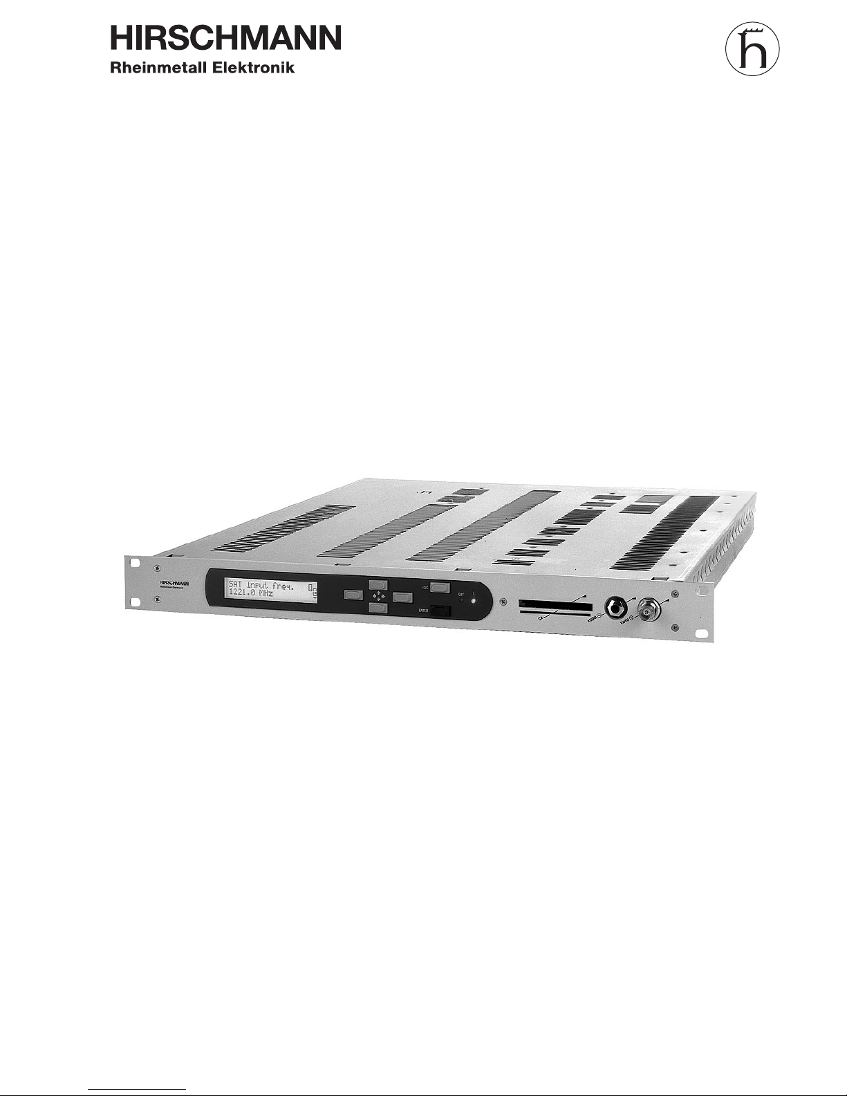
The Integrated Receiver Decoder IRD 8500/QP serves for converting a QPSK SATsignal with MPEG-2 standard into a video-baseband-signal with the standard PAL,
NTSC or SECAM according to ITU-R BT624 (PAL-B/G). The audio signal is also converted into the baseband. The IRD 8500/.. also supports the decoding of encoded data
(software option). All CA-modules which use the Common Interface are supported.
With its optional MPEG-interface an MPEG-input and an MPEG-output are also available. With option LNB supply the supply voltage 13/18V and the control signal 22kHz
are available.
Design
View
The IRD 8500/.. is built as a 19" slide-in module with 1HU height.
The front-panel contains:
l
the display
l
the LED’s
l
the operating elements
l
the video monitoring output
l
the audio monitoring output
l
opening to slide-in the Conditional Access Module
The rear-panel contains:
l
the mains connection
l
1.SAT-IF input
l
video-signal outputs
l
RS232 interface
l
10 Mbit Ethernet-interface
l
remote monitoring interface ”ALARMS”
Cooling The IRD 8500/.. is cooled by convection.
Putting into operation
IRD 8500/..
2 - 2 Intergrated Receiver Decoder
Integrated Receiver Decoder IRD 8500/..
Page 13

Power supply
Depending on the model the IRD 8500/.. can be operated with the following mains voltages:
l
115 VAC
l
230 VAC
ATTENTION: Before operation make sure that the mains voltage matches
the supply voltage indicated on the device.
The mains fuse is located beside the mains socket. The IRD 8500/.. does not have a
mains switch. To disconnect the IRD 8500/.. from the mains, the mains plug must be
pulled out of the device.
Control
General For controlling there are the following possibilities:
l
Keypad and display on the IRD 8500/.. .(see chapter ”Menu operation”)
l
10Mbit Ethernet-interface (software option “Network Access Control”)
l
RS 232 Interface for stand-alone devices (software option “Network Access
Control”)
Remote control in a
network
(software option)
The IRD 8500/.. can be remote controlled via the Ethernet- or RS232-interface. A standard WWW-browser with TCP/IP protocol (e.g. Internet Explorer) is to be used. The
remote control can be disabled on the IRD 8500/.. .
Monitoring
General For monitoring there are the following possibilities:
l
keypad and display
l
LED’s ”f” and ”OUT” (see interfaces and operating elements)
l
Monitoring output ”VIDEO m ”, monitoring output ”AUDIO m ”
l
10 Mbit Ethernet-interface (software option “Network Access Control”)
l
RS 232 Interface for stand-alone devices (software option “Network Access
Control”)
l
Remote monitoring interface ”ALARMS”
l
History / operation log (see menu operation)
l
Status display (see menu operation)
Remote monitoring interface ”ALARMS”
On the remote monitoring interface ”ALARMS” the status messages ”ALARM” and
”WARNING” are signalled via two floating double-throw contacts.
To the floating double-throw contacts external error indicators ( e.g. siren, lamp) can
be connected. The pin-assignment is shown in chapter ”Interfaces and operating elements”.
Putting into operation
IRD 8500/..
Intergrated Receiver Decoder 2 - 3
Page 14

SAT-receiver/demodulator
Input frequency
menu
”Input frequency"
”Input level"
”Frequency offset”
”Tuner status”
The input frequency can be adjusted in a range from 920 ... 2150 MHz in steps of 0,1
MHz. The current signal strength as well as the frequency offset of the input signal can
be queried. The displayed frequency offset is defined as follows: offset = received frequency - set frequency. The software is tracking the frequency, until the tuner is locked. The current status (locked/unlocked) can be queried. For monitoring a warningand an alarm threshold can be defined for each parameter.
Symbol rate
Menu ”Input symbol rate”
The symbol rate of the input signal is to be adjusted according to the input signal. It
can be set in a range from 4 ... 45 MSymb/s in steps of 0,1 kSymb/s.
Transport stream
Menu ”TS identifier”
When entering a SAT-input frequency a search starts in a range of ± 8MHz of the set
mid-frequency to find present transport streams. The transport stream identifier (ID)
and the input frequency of the transport streams are displayed.
Unique identification of a transport stream is only possible with the TS ID.
The displayed input frequency of a transport stream can vary about the frequency deviation of the LNC-oscillator.
The desired transport stream is to be selected from the available transport streams.
Bit Error Rate
Menu
”Input BER after V.”
The BER of the MPEG-signal can be queried after the Viterbi-decoding.
A warning- or an alarm threshold can be defined.
Code rate input signal
Menu ”Input code rate”
The code rate of the input signal can be queried. The code rate can be monitored by
defining a warning- or an alarm message.
Carrier to noise
Menu ”Input C/N”
The C/N-ratio of the input signal is measured and can be queried. A warning- or an
alarm threshold can be defined.
LNB remote supply
Menu “LNB supply”
With the option “LNB supply” this menu is displayed. The LNB remote supply is used
for the direction of the polarity and is available with 13V (vertical) or 18V (horicontal).
LNB control
Menu “LNB 22kHz”
With the option “LNB supply” this menu is displayed. The 22kHz control signal is used
for the selection of the receiving frequency band.
Putting into operation
IRD 8500/..
2 - 4 Intergrated Receiver Decoder
Page 15

MPEG processing
MPEG-input
Menu ”MPEG input”
According to the desired source of the MPEG-signal, the MPEG input has to be
pre-selected. There are following possibilities available:
l
SAT
l
SPI
l
TSI (only with the option “MPEG interface” available)
Program selection
Menu ”Select service”
The programmes present in the transport stream are displayed. The desired programme must be selected. In order to read the entire displayed text for long programme
descriptions, the text can be scrolled (see menu operation).
In the beginning of each programme description a symbol is positioned which shows
the current status of decoding.
The following indications are possible:
l
”#” encoded programme
l
”?” programme is not decoded correctly
l
”+” programme is decoded correctly
When changing a programme, a programme interruption occurs for approx. 2sec. during re-initialization.
Demultiplexer and
decoder status
Menu
”Demux status”
”Decoder status”
If the demultiplexer is synchronized with the MPEG-input data stream, ”sync ok” is displayed. If the decoder can decode the signal correctly, ”play” is displayed, otherwise
”idle” is displayed. Monitoring of the corresponding states can be done by setting warning- or alarm messages.
Test lines
Menu ”Test lines”
The test lines pre-assigned for the respective standard ( see Appendix / Technical
data) can be switched off.
VPS data, sound status
Menu ”VPS”
The VPS-data as well as the sound status (mono/stereo/2-tone) present in the MPEGinput signal are inserted into the data line 16. The VPS-data can be switched off.
Teletext
Menu ”Teletext”
Teletext data present in the MPEG-input signal can be inserted into the video signal.
Closed captioning
Menu ”Closed caption”
For NTSC, data of the MPEG-signal coded in the picture can be transmitted. This
function can be switched off.
Wide screen
Menu ”Wide screen sign.”
For PAL-plus the information ”wide screen signalling” is inserted into line 23, if a corresponding picture format is present at the input. This function can be switched off.
Putting into operation
IRD 8500/..
Intergrated Receiver Decoder 2 - 5
Page 16

Conditional Access (Option)
Selection CAapplications
Menu ”CA-applications”
Applications available on the CA-card can be queried. The application for the desired
programme is to be selected.
CA-card menu
Menu ”CA-menu”
Menus available on the card can be selected here. The description of the menu items
can be found in the documentation of the CA-card.
Video processing
Image format
Menu
”Format processing”
The format of the output image of the IRD 8500/.. is set with 4:3.
If a 16:9 input format is present, adaptation to the output format can be set in 3 different ways:
l
pass-through (not defined output image)
l
letter box (vertical filter, black bar on the upper and lower image margin)
l
pan & scan (expanding to the total image height, trimming the left and right
margin)
Test signal
Menu ”Color bar”
The IRD 8500/.. provides a EBU color bar testsignal 100%.
Output switch-off
Menu ”Video output ”
The video baseband output can be switched off. Switch-off of the output signal is recommended when settings are changed on the IRD 8500/.. .
TV Standard For the baseband video signal the following TV-standards are available:
Menü ”Video mode”
l PAL
l NTSC
l
SECAM
If the TV-standard is changed, a warm reset is performed on the IRD 8500/.. .
Putting into operation
IRD 8500/..
2 - 6 Intergrated Receiver Decoder
Page 17

Audio processing
Language selection
of the sound
Menu ”Select language”
The language of the sound can be selected in the menu. When changing the language, the programme is interrupted for approx. 2 seconds.
Selection of the mode
of the sound
The audio baseband output can be selected from the following possibilities:
Menu ”Audio Mode”
l
Mono
l
Stereo
l
2-Tone R
l
2-Tone L
The selection of the audio baseband signal does not influence the sound coding
(mono, stereo, 2tone) carried out by the MPEG input signal.
Mute switching of the
audio signal
Menu ”MUTE”
The audio base band signal can be switched off.
Audio output level
Menu ”Audio level”
The output level can be adjusted in a range from -3 ... 12 dBm (600 ohm) in steps of
minimum 0,1 dB.
Putting into operation
IRD 8500/..
Intergrated Receiver Decoder 2 - 7
Page 18

Block diagram
Putting into operation
IRD 8500/..
2 - 8 Intergrated Receiver Decoder
1st SAT-IF e
AUDIO a
AUDIO m
VIDEO a
VIDEO a
VIDEO m
D
A
Video -
Encoder
FPGA
MPEG-
Decoder
MPEG-
Demux
Data
Latch
Data
Latch
Common
Interface CI
SAT-
Demodulator
Option
MPEG-
Interface
mC
to Conditional
Access Module
MPEG SPI
input
MPEG SPI/ASI
output
TTX
OUT
LCD/
Keyboard
RS 232
Alarms
Ethernet
Monitoring/
Control
Power Supply
230/115 VAC
Block diagram Integrated Receiver Decoder with option MPEG-interface
Page 19

Interfaces and operating elements
Front-panel
View
[1] Display (two lines with 20 characters each)
[2] Cursor keys
[3] ESC-key
[4] ENTER-key
[5] LED ”OUT” lights up green, if input signal is correctly processed and an output
signal is present.
[6] LED ” f ” lights up red in case of an alarm or hardware error. In addition the dis-
play shows which error occured ( e.g. ”ERROR: sync nok”).
[7] Slide-in place for Conditional Access Module
[8] AUDIO-monitoring output ”AUDIO m” (6.3mm jack socket; 600 ohm)
[9] VIDEO-monitoring output ”VIDEO m” (BNC-socket 75 ohm)
Putting into operation
IRD 8500/..
Intergrated Receiver Decoder 2 - 9
[1]
[3]
[4]
[5]
[2]
[6]
[7] [8] [9]
OUT
ESC
ENTER
AUDIOm
CA
VIDEOm
Integrated Receiver Decoder IRD 8500/..
Page 20

Rear-panel
View
[1] 1. SAT-IF input ”SAT IF e” (F-socket)
[2] VIDEO output ”VIDEO a” (BNC-socket; 75 ohm)
[3] VIDEO output ”VIDEO a” (BNC-socket; 75 ohm)
[4] left audio baseband output ”AUDIO L a” (XLR-socket, 3-poles)
[5] right audio baseband output ”AUDIO R a” (XLR-socket, 3-poles)
[6] Serial output “ASI a” (BNC-socket, 75 ohm)
[7] Parallel output “SPI a” (25-pole sub-D-socket)
[8] Parallel input “SPI e” (25-pole sub-D-socket)
[9] remote monitoring interface ”ALARMS’ (9-pole sub-D-socket)
[10] ”RS 232" interface (9 pole sub-D-socket)
[11] 10 Mbit Ethernet-interface ”10BASE-T” (RJ-45 Stuart connector)
[12] LED ”LINK” (lights up when Ethernet connection is electrically correct)
[13] mains connection ”MAINS”
[14] mains fuse
Putting into operation
IRD 8500/..
2 - 10 Intergrated Receiver Decoder
[1] [3]
[4] [5] [6] [7] [8]
[9]
[2] [10] [11]
[12]
[13] [14]
SAT IFe VIDEOa VIDEOa
AUDIO L
a
AUDIO R
a
RS 232
10BASE-T MAINS
230V -/315mAT
115V -/630mAT
LINK
ALARMS
ASI
SPI
SPIe
Integrated Receiver Decoder IRD 8500/..
Page 21

Pin-assignment RS232interface (socket)
Pin Remark
1 not used
2 RXD (Receiving Data)
3 TXD (Transmitting Data)
4 not used
5 ground
6 ... 9 not used
Pin-assignment interface
”ALARMS”
The double throw contacts are dimensioned for the following values:
l
Maximal switchable voltage 30 VDC or 42 VAC *(SELV acc. to
EN60950)
Maximal switchable current 0,5 A
*SELV....low voltage circuit (safety extra-low voltage)
Pin Remark
1 break contact (alarm)
2 base contact (alarm or warning)
3 make contact (warning)
4 REMOTE_2 (programmable input)
5 ground
6 break contact (alarm)
7 make contact (warning)
8 REMOTE_1 (programmable input)
9 +12V/Ri=560Ohm
Putting into operation
IRD 8500/..
Intergrated Receiver Decoder 2 - 11
5
1
9
6
5
1
9
6
REMOTE
3
7
2
ALARM
6
1
2
WARNUNG
wiring of the alarms
Page 22

Pin-assignment 10 Mbit
Ethernet interface
The Ethernet interface is using a RJ-45 Stuart connector.
Pin Remark
1 RD+ Receive data (positive)
2 RD- Receive data (negative)
3 TD+ Transmit data (positive)
6 TD- Transmit data (negative)
4/5/7/8 not used
Putting into operation
IRD 8500/..
2 - 12 Intergrated Receiver Decoder
1
Page 23

Start-up
ATTENTION: Operating work must be carried out by personell with
RF-knowledge.
ATTENTION: If the device is steamed up after unpacking, it must be acclimati-
zed at least one hour before starting operation.
ATTENTION: During operation the vents must not be covered. When mounting
the device in a rack, take care that there is a gap of at least 1 HU
between the devices.
NOTE: When building in the device in a rack use rails or any other suitab-
le mount.
NOTE: Before operation read the chapter ”Menu operation”.
Procedure
1. Check if the supply voltage shown beside the mains socket matches the mains
voltage.
ATTENTION: A wrong mains voltage will cause a defect in the IRD 8500/.. .
Therefore check the mains voltage before connecting the module
to the mains.
2. Slide in the IRD 8500/.. into the intended place in the 19" rack.
3. Fix the module with the 4 screws on the front-panel.
4. Connect the signal cabling.
5. Connect the IRD 8500/.. to the mains ( boot procedure starts)
6. Check the LC-display.
7. Adjust the contrast of the LC-display (see menu operation ”display / contrast”)
Putting into operation
IRD 8500/..
Intergrated Receiver Decoder 2 - 13
Page 24

8. For the first start-up use the help of the ”setup assistent”.
This menu is entered by calling up the sub-menu ”factory setting” under ”setup”.
After the IRD 8500/.. was reset to the factory settings you are queried whether you
want to use the help of the setup assistent or not.
If your answer is ”Yes”, the following parameters must be entered:
l
MPEG input (SAT, SPI, TSI)
l
Sat input frequency (1st SAT-IF level)
l
Input symbol rate (4 ... 45 MSymb/s)
l
TS identifier (selection of the transport stream)
l
Select service (selection of the program)
l
Select language (selection of sound2)
With ”finished” you return to the main menu. The IRD 8500/.. is now ready for operation.
9. Check the LED´s on the front-panel.
l
LED ” f” does not light up
l
LED ”OUT” lights up
10. Check the operating parameters of the IRD 8500/.. in the menus
”Sat receiver”, ”MPEG processing”, ”Conditional access”, ”Video processing” and
”Audio processing”.
11. For optimizing the IRD 8500/.. adjust the settings of all other parameters (e.g. ”Audio level”) in the menus.
12. Set the desired warning- and alarm thresholds for the displayed values.
Putting into operation
IRD 8500/..
2 - 14 Intergrated Receiver Decoder
Page 25

Menu tree
General The menu tree of the IRD 8500/.. shows the following main menus:
l
Sat receiver setting the SAT-parameters
l
MPEG processing setting of specific programme parameters,
test lines, VPS, Teletext, etc.
l
Conditional Access setting of CA-parameters (software option)
l
Video Processing setting of video parameters
l
Audio Processing setting of audio parameters
l
History/Status query of status, history and operation log
l
Setup setting the device configuration
l
Network setting and query of the network parameters
l
Miscellaneous query of device configuration, entry of PIN-codes
Menu tree
Menu operation
IRD 8500/..
3 - 2 Intergrated Receiver Decoder
MPEG
processing
Sat
receiver
Conditional
Access 1)
IRD video
Input frequency
Input symbol rate
Tuner status
TS identifier
Input level
Frequency offset
Input BER after V.
Input coderate
Input C/N
LNB supply 2)
LNB 22kHz 2)
CA-applications 1)
CA-menu 1)
Format processing
Color bar
Video output
Video mode
Select language
Audio mode
Muting
Audio level
MPEGinput
Demuxstatus
Selectservice
Decoderstatus
Testlines
VPS
Teletext
Closed caption
Widescreensign.
Video
processing
Audio
processing
Page 26

Menu tree
1) Function if the software option Conditional Access Control (CAC 8000) is installed.
2) Function only with the option “LNB supply” available
Menu operation
IRD 8500/..
Intergrated Receiver Decoder 3 - 3
Status/
History
Network
Miscellaneous
Device status
History show
History delete
Extended messages
Network access
Remote control
Online users
Ethernet status
Ethernet config.
PPP status
PPP configuration
Mail settings
Module info
Temp.
Changepassword
DeviceIDmenu
Date&Time
ResetAlarms/Warn.
Factorysettings
Contrast
Device PINcode
Setup
Page 27

Menu operation
Operation
Cursor keys The IRD 8500/.. is operated via the key pad on the front-panel. With the cursor keys
“á” and “â” you can select the desired menu item. With the cursor key “à” you enter
the desired menu. With the cursor keys “á” and “â” you can select the desired function in the sub-menu.
ESC-key With the ESC-key you can move one level up in the menu tree.
ENTER-key With the ENTER-key you select a setting or a measured value, and confirm an entry.
Change settings
Select the value to be changed by pressing the ENTER-key.
l
Position the cursor with the keys “ß” and “à” and set the desired value with the
keys “á” and “â”.
You can exit a configuration menu in the following way:
l
to confirm the entry press the ENTER-key
l to cancel the entry press the ESC-key
l to exit the menu press the ESC-key or the key “ß”
l
If a value is changed, a range-window shows up on the display. The
vertical line represents the value currently set.
When changing the value, the line is moving along in the range-window. If the possible
adjustment range is left, it is indicated by an arrow. Input values outside the valid range are not accepted.
An error message “value out of range !” is displayed.
On the right margin of the display an information bar is located. The following displays
are present:
Arrow to the top or to the bottom : further menus can be selected by
using the cursor keys.
Arrow to the right: by using the ““à””-key a submenu can be selected.
Menu operation
IRD 8500/..
3 - 4 Intergrated Receiver Decoder
Page 28

Display of an “E” : the currently selected setting can be edited/changed.
Display of an “L” : for the currently selected status resp. value a warning- or alarm-messge can be defined.
Alarm and warning messages
By pressing the ENTER-key an alarm- and warning threshold value for a status message or displayed value can be defined.
With the cursor keys “ß” and “à” the text can be scrolled through.
With the keys “á” and “â” the following settings can be changed:
l
selection between alarm and warning message
l
selection of the message state: “EN” enables the message, “dis” disables the
message.
l
selection of condition for status indication (e.g. “if sync ok” or “if sync not ok”
l
the thresholds for display values (upper limit, lower limit) can be selected and
changed. (see change settings)
Confirmation of the entries with the ENTER-key.
Password protection
Menu “Change password” You can provide the IRD 8500/.. with a password protection. At delivery the password
is “0000". Password query is suppressed with this password. To protect the IRD
8500/.. from unauthorized use you have to change the password.
However, query of the parameters and settings is possible at all times.
After entering the password (query) all settings can be changed without restrictions. If
no key is pressed during a period of 30 minutes, the device changes back into the protected mode.
Repeated entry of the current password in the menu or the entry of a new password
causes the device to change immediately to protected mode.
NOTE: Write down the changed password. In case of loosing your
password contact the next service center.
Menu operation
IRD 8500/..
Intergrated Receiver Decoder 3 - 5
Page 29

Configuration / Identification
Device identification
Menu “Device ID: menu”
For device identification in a network additional information of the device can be stored. The following sub-settings are possible:
for example:
l
ID: long name [ 30 characters ] *** Hirschmann ***
l
ID: short name IRD 8500 (pre-assigned)
l
ID: rack [ 2 characters ] A1
l
ID: mainframe [ 2 characters ] 10
l
ID: location [ 20 characters ] Rankweil 3
l
ID: network [ 30 characters ] Rheinmetall
l
ID: channel [ 30 characters ] evaluation 8500
Device identification
Menu “Module info
The information about the current device configuration can be queried. For each
mounted assy the following information is available:
l
SW-Vers Current software-version
l
GUI-V. Version for the graphical user interface
l
Ord.Nr. Hirschmann ordering number
l
Ser.Nr.: Serial number of the assy
l
G-Nr. Hardware version of the assy
l
SG-Nr. Software-version of the assy
l Prod. Date of production
l Rep. Date of last repair
l
Build: Number of compiling
If information is not available (e.g. the assy has no software) the message “—” is displayed.
Status display / history / operation log
Status messages
Menu “Device status”
If status messages are present, the message with the highest priority is scrolled
across the upper line of the display in the main menu.
NOTE: The submenus do not contain a status line.
After booting the device the upper line of the display shows “IRD 8500 all ok” as well
as the name stored under “Setup\Device ID: menu\Device ID:long name”
Further messages about current errors, alarms and warnings can be queried.
The message text can be seen by selecting the next submenu. By using the cursor
keys, the individual message texts can be read as a whole.
(exit with ESC-key)
If an error or warning message appears on the LC-display, it is likely that you will find
some additional information in the history.
Menu operation
IRD 8500/..
3 - 6 Intergrated Receiver Decoder
Page 30

History / operation log
Menu
“History show”
“History delete”
All errors, alarms and warnings that occurred as well as changes in the device settings
are stored in an operation log. The records are displayed with current time and date
and a consecutive number. The entries (max.250) can be queried. The most recent
events are stored with the lowest number.
If a threshold value is exceeded, a [+] in front of the message indicates that the valid
range was left. If the value returns into the valid range, a repeated entry with a [-] in
front of the message is shown.
The message text can be seen by selecting the next submenu. By using the cursor
keys, the individual message texts can be read as a whole.
(exit with ESC-key)
The information stored in the history can only be deleted as a whole.
Menu
“Extended messages”
Is not used in the IRD 8500/.. for the time being.
Preset / Reset
Preset
Menu “Factory settings”
If the complete IRD 8500/.. shall be reset to the factory settings, a preset has to be
performed, which sets back all parameters and all alarm and warning thresholds to the
factory settings.
After the preset is executed, a “set up assistent” is available for easy putting into operation (see chapter “putting into operation” ).
Reset
Menu “Reset
Alarms/Warn.”
The alarm and warning thresholds can be de-activated individually for each measuring
parameter or all alarm and warning thresholds can be de-activated at once.
Network
Network access
Menu
“Network access”
Network access can be disabled (e.g. in order not to cause remote error messages
when doing maintenance work or setting changes).
For the network access the following possibilities are available:
l
FREE full access, all read/write possibilities are available
(option Network Access Control)
l
Update only only an update of the flash-software can be performed
(if no software option was ordered)
Menu “Remote control” If “Remote control” is set to “OFF”, the remote control is disabled, which means that
that remote control center is still able to receive messages from the equipment (e.g.
configuration changes made by a local operator), but cannot change the configuration
any more.
Menu “Online users” Indication of the present number of guest / operators / ftp connections
Menu operation
IRD 8500/..
Intergrated Receiver Decoder 3 - 7
Page 31

Network status
Menu “Ethernet status”
If the IRD 8500 is used in a network with automatic DHCP-address assignment, the
address assigned by the server is displayed.
Interruption of an existing network connection causes the error message
“Ethernet offline”.
Network configuration
Menu
“Ethernet configuration”
Ethernet configuration is carried out via a desktop PC. Necessary additional information about the submenus listed below can be found in the online help.
NOTE: Before you connect the IRD 8500 to the network,
contact your network provider
For the network configuration the following menu items are available:
l
Network mode (setting of the DHCP address auto/man; when changing the
setting, the CPU on the board “Controller Assy” performs a reset)
l
Network IP (is assigned when DHCP is auto, to be set in manual mode)
l
Network IP mask (is assigned when DHCP is auto, to be set in manual mode)
l
Network gateway IP (is assigned when DHCP is auto, to be set in manual mode)
l
Network DNS IP (is assigned when DHCP is auto, to be set in manual mode)
l
Network MAC chip address of the Ethernet-controllers
Menu “PPP status” Indication of the availability of the PPP connection (remote control RS 232).
Menu “PPP configuration” For the PPP connection (for stand-alone devices) the following menu items are
available:
l
PPP baudrate: Input of the baudrate for the RS 232 connection
l PPP IP: Input of the IP address of the BS8000 devices
l
PPP remote IP: Input of the IP address of the PC
l
PPP login name: Input of the user ID
l
PPP login password: Input of the password
Mail
Menu “Mail settings”
In network operation, configuration of the mail parameters is to be carried out via the
submenus of this menu.
l
Netmail sending: Select the type(s) of messages you want to send (e.g. Errors and
warnings). If you, for example, select +INFO errors, warnings and info will be sent.
Errors will reduce the messages to error only.
l
Netmail server IP: Input of the mailserver IP
l
Netmail account: Input of the mail account
l
Netmail dest.: Input of the email address
l
Netmail delay: Input of the delay for sending mail
l
Netmail send testmail: This menu item permits to sends a test mail
Menu operation
IRD 8500/..
3 - 8 Intergrated Receiver Decoder
Page 32

Display
Illumination The display illumination is automatically switched off, if no key is pressed on the IRD
8500/.. for 15 minutes. When pressing any key the illumination switches on again.
Display contrast
Menu “Contrast”
The contrast of the display can be adapted to the light conditions in the room.
Date / Time / Temperature
Date / Time
Menu “Date & Time”
The time settings stored in history are derived from this clock.
Format: [ YYYY:MM.DD HH.MM.SS ]
Temperature
Menu “Temp.”
The temperature in the housing is measured. The current value can be queried.
PIN-Code
Release of options
Menu “Device PIN code”
If the input of a PIN-code is necessary for the release of an option, it has to be entered in this menu. If the code is correct the message “Code accepted” is shown. If the
code is incorrect, the message says “Code not accepted”.
Menu operation
IRD 8500/..
Intergrated Receiver Decoder 3 - 9
Page 33

Important notes
ATTENTION: Maintenance work must be carried out by trained staff with
RF-knowledge.
ATTENTION: In case of a technical problem send your IRD 8500/.. to your next
service center for repair.
NOTE: Please go to our service homepage http://service.hirschmann.at
to find other helpful information.
Maintenance
IRD 8500/..
4 - 2 Intergrated Receiver Decoder
Page 34

Functional check
Procedure
For a functional check it is sufficient to check the nominal states of the LED´s on the
front panel and the operating parameters on the display.
Nominal operation state
LED’s
l
LED ” f ” does not light up
l
LED ”OUT” lights up
Menu
”MPEG processing”
l
DMX state sync ok
l
Decoder state play
Menu
“Video processing
l
Output signal On
Menu
“Audio processing”
l
Audio mute Off
All other operating parameters are programme- or system-dependent.
Maintenance
IRD 8500/..
Intergrated Receiver Decoder 4 - 3
Page 35

Help with problems
LED indications
Failure Repair
LC-display display
remainsdark
- Press any key.
- Check the power supply.
- Check the mains fuse.
- Change the IRD 8500/.. .
red LED ” f ” lights up - An alarm was triggered. Check which alarm is active
in the history. Solve the problem or change the
alarm threshold.
- An existing Ethernet connection was interrupted.
Restore the connection.
- Change the IRD 8500/.. .
LED ”OUT” does not light up
DMX state: “sync. not ok”
Decoder state: “idle”
- Check the input signal (frequency, level, polarity, etc.)
- Check the following settings:
- Input frequency
- Input level
- Symbol rate
- LNB supply (option LNB supply)
- LNB 22kHz (option LNB supply)
- Tuner state
- Restore the factory settings with PRESET and
re-configure the device.
LED ”OUT” does not light up
DMX state: sync ok
Decoder state: play
- Check the following settings:
- Video output
- Restore the factory settings with PRESET and
re-configure the device.
LED ”OUT” lights upno
sound or sound very soft
- Check the following settings:
- Audio mute
- Audio gain
- Check if the audio operating outputs are connected
to the “IRD assy”
- Restore the factory settings with PRESET and
re-configure the device.
NOTE: Error messages, which are inserted on the LC-display, are listed in
the appendix.
Maintenance
IRD 8500/..
4 - 4 Intergrated Receiver Decoder
Page 36

Change
Changing the mains fuse
ATTENTION: Danger of electric shocks !
Disconnect the IRD 8500/.. from the mains before
changing the fuse !
Procedure 1. Disconnect the IRD 8500/.. from the mains.
2. The fuseholder is located beside the mains socket. Open the bayonet lock of the
fuse holder with a screw driver.
3. Replace the defective fuse ( 5x20 mm). The fuses have, depending on the mains
voltage, the following values:
l
230 V mains connection 0,315 AT
l
115 V mains connection 0,63 AT
Changing the battery
ATTENTION: Danger of electric shocks ! Disconnect the IRD 8500/.. from the
mains before
changing the battery !
WARNING: Improper change of the battery may cause an explosion.
Replacement only by the same or an equivalent type
recommended by the manufacturer !
ATTENTION: Lithium batteries must not be disposed of as domestic waste !
Send the used batteries back to the manufacturer or
supplier. Address of the manufacturer of the battery:
Firma RENATA AG
Kreuzenstr. 30
CH-4452 Itingen
NOTE: The data in the ERROR history and the note entries ( when using
in the network ) get lost when the battery is changed.
Maintenance
IRD 8500/..
Intergrated Receiver Decoder 4 - 5
Page 37

1. Disconnect the IRD 8500/.. from the mains.
2. Loose the screws on the cover and remove it.
3. Replace the empty lithium battery by a new one (lithium battery CR 2477N 3V/
1000mAh; Manufacturer: RENATA)
4. Watch out for the correct polarity of the battery !
5. Close the cover.
6. Reconnect the device to the mains.
7. Carry out a functional check ( see chapter ).
Maintenance
IRD 8500/..
4 - 6 Intergrated Receiver Decoder
1
Lithium Batterie 3V
lithium battery 3V
Explosionsgefahr bei
unsachgemäßem Austausch
der Batterie.
Explosion risk by improper
replacement of battery.
Top view of Integrated Receiver Decoder with open cover (only CPU board)
Page 38

Fitting of options
General
The option MPEG-interface can also be fitted after the installation.
l
First disconnect the IRD 8500/.. from the mains.
l
Open the cover.
l
Install the option MPEG-interface or “LNB supply” according to the installation instruction enclosed.
l
Close the cover.
l
Reconnect the IRD 8500/.. to the mains.
l
The option is automatically detected by the software. Perform the necessary
settings in the menus. ( e.g. change MPEG-input to TSI).
Maintenance
IRD 8500/..
Intergrated Receiver Decoder 4 - 7
ge rt ws bl
br sw
1
2
1
2
1
ws
bn
IRD-ASSY..-IRD..../.
ORD.NUM.: 888075-00.
.......................
1
2
39
Option
MPEG-Interface
Option
LNB supply
Connection CPU - IRD
Top view of Integrated Receiver Decoder with open cover
Page 39

Software update
A software update can be carried out via the Ethernet interface (for headends with several BS8000 devices) as well as via the RS232 interface and a PPP connection (for
stand-alone BS8000 devices). If a software update is necessary, all the information
about the update will be enclosed in the upgrade package.
NOTE: You can download the software update with the update
information from the software update section on our service homepage http://service.hirschmann.at. Look for the ordering number given below. The update sectin is protected by password. To obtain
the present password please contact service@rw.hirschmann.at.
The password is changed monthly.
Ordering description: Software SW CPU-IRD 8500
Ordering number 879 310-814
Ordering description: Software SW IRD 8500
Ordering number 879 310-808
Handling
Storage
We recommend to store the IRD 8500/.. in the original packaging.
Pay attention to the following parameters:
l
Temperature -20 ... +70oC
l
Relative humidity 20 ... 80 %
Transport
We recommend to transport the IRD 8500/.. in the original packaging. Watch out that
there is no mechanical stress on the connectors and operating elements.
Disposal
The device must be recycled / disposed of after duly operation according to the national disposal regulations.
We recommend in case to contact the local authorities.
Maintenance
IRD 8500/..
4 - 8 Intergrated Receiver Decoder
Page 40

Ordering information
Ordering information Integrated Receiver Decoder for 230 V mains connection
Model Type Part number
Input SAT-QPSK-signal IRD 8500/QP 977 160-001
Input QAM-signal IRD 8500/QA 977 160-002
Input OFDM-signal IRD 8500/OF 977 160-003
Input MPEG-signal IRD 8500/MP 977 160-004
Ordering information Integrated Receiver Decoder for 115 V mains connection
Model Type Part number
Input SAT-QPSK-signal IRD 8500/QP 977 160-101
Input QAM-signal IRD 8500/QA 977 160-102
Input OFDM-signal IRD 8500/OF 977 160-103
Input MPEG-signal IRD 8500/MP 977 160-104
Ordering information for options
Hardware Description Type Order number
MPEG interface AS-MPI 8505 888 224-001
LNB supply AS-LNB 8500/75 888 076-001
Software Description Type Order number
Conditional Access Control CAC 8000 879 310-809
Network Access Control NAC 8000 879 310-810
NOTE: When ordering the Network Access Control Software, both the se-
rial number of the IRD 8500/.. (see “Miscellaneous\Module info”)
and the MAC number of the Ethernet controller have to be stated
in addition to the part number.
The MAC number can be queried on the device.( see menu “Network\Ethernet configuration\network MAC)
NOTE: When ordering the Conditional Access Control Software, also the
serial number of the IRD 8500/.. (see “Miscellaneous \
Module info) has to be stated in addition to the part number
The software options are released with a PIN-code.
Maintenance
IRD 8500/..
Intergrated Receiver Decoder 4 - 9
Page 41

Services
Maintenance
IRD 8500/..
4 - 10 Intergrated Receiver Decoder
Austria
Germany
Benelux
France
Great Britain
Singapur
Spain
Ungarn
USA/Canada
Internet
Hirschmann Austria GmbH Tel. +43-(0)5522/307 0
Oberer Paspelsweg 6-8 FAX +43-(0)5522/307 555
A-6830 RANKWEIL-BREDERIS Email info@rw.hirschmann.at
Hirschmann Electronics GmbH & Co. KG Tel. +49-(0)7127/14 0
Stuttgarter Str. 45 - 51 FAX +49-(0)7127/14 1214
D-72654 NECKARTENZLINGEN Email info@nt.hirschmann.de
Richard Hirschmann Tel. +31-(0)2944 62 555
Electronice Nederland B.V. FAX +31-(0)2944 80 639
Postbus 92 Email ibn@hirschmann.nl
NL-1380 AB WEESP
Richard Hirschmann Tel. +33-(0)1/3933 02 80
Electronique S.A. FAX +33-(0)1/3990 59 68
24, rue du Fer à Cheval, Z.I. Email erempfer@hirschmann.fr
F-95200 SARCELLES
Richard Hirschmann Tel. +44-(0)1234/34 5999
Electronics UK Ltd. FAX +44-(0)1234/35 2222
St. Martins Way Email richardhirschmann@
St. Martins Business Centre compuserve.com
GB-BEDFORD MK42 OLF
Hirschmann Electronics Pte Ltd Tel. +65 / 382 2055
3, Howard Road FAX +65 / 382 2755
Tat Hong Industrial Building #04-00 Email hirschmann.ap@pacific.net.sg
SGP-Singapore 369 578
Hirschmann Espania S.A. Tel. +34-(0)91/746 1730
c/Trespaderne, 29 FAX +34-(0)91/746 1735
(Barrio del Aeropuerto) Email hes@hirschmann.es
Edifica Barayas 1, 2a Planta
E-28042 MADRID
Hirschmann Hungaria Kft. Tel. +36-(0)13/49 41 99
Rokolya u. 1-13 FAX +36-(0)13/29 84 53
H-1131 BUDAPEST Email hirschmann.budapest@
mail.matar.hu
Hirschmann Electronics, Inc. Tel. +1-973/830 2000
30 Hook Mountain Road - Unit 201 FAX +1-973/830 1470
PINE BROOK, N.J. 07058 Email ischnaitmann@
USA hirschmann-usa.com
http://www.hirschmann.de
http://service.hirschmann.at (e.g. Software update)
Page 42

General data
Nominal temperature range : +5 ... +40oC
Operation temperature range : 0 ... +45oC
Storage temperature range : -20 ... +70oC
Cooling : Convection
Dimensions (WxDxH) :483x490x44mm
(19" cabinet mit 1 HU)
Mounting depth without cabling : 450 mm
Weight : max. 6.0 kg
Connections
Mains : Compact mains plug
1. SAT IF-input F-socket
VIDEO-output : 3 x BNC-socket
AUDIO-output : Audio-socket, type XLR 3-poles
AUDIO-monitoring output : 6,3mm jack socket
Technical data
Power supply Mains voltage:
115 V version : 97 ... 132 VAC
230 V version : 195 ... 264 VAC
Mains frequency : 48 ... 62 Hz
Mains fuses:
for 230 V : 0.315 A slow
for 115 V : 0.63 A slow
Power consumption at nominal load : max. 24 W (without options)
EMV : EN 50083-2/A1 edition 9/95 +
A1 edition 3/97
Safety standard : EN 60065 (edition April 94)
Appendix
IRD 8500/..
6 - 2 Intergrated Receiver Decoder
Page 43

Input 1. SAT-IF input “SAT IF e”:
Impedance : 75 ohm
Frequency range : 950 ... 2150 MHz
Level : -65 ... -25 dBm
Tuning increment : 0.1 MHz
AFC captur range : ± 8 MHz
Return loss : ≥ 8 dB (typ.: ≥ 12 dB)
Oscillator inteference level : ≤ -63 dBm
Frequency 2.SAT-IF : 479.5 MHZ
IF-bandwidth : 55 MHz
Demodulation : I/Q or I/-Q
Direction of rotation : automatically detected
Spectral sharping : cos roll off 35%
Output-symbol rate : 4 ... 45 MSymb/s
Smallest adjustment step : 0.1 kSymb/s
Decoding : acc. to DVB standard ETS 300421
Remote supply LNB
vertical : 12,5 ... 14,0 V / max. 310 mA
horicontal : 17,2 ... 18,8 V / max. 310 mA
22 kHz control signal :f=20...24kHz; Zi = 15 Ohm;
Upp= 500 ... 800 mV
Synchronous Parallel Interface input “SPI e” (Low Voltage Differential Signal)
Datarate : 2 ... 64 Mbit/s
Clock frequency : 250 kHz ... 8 MHz
Frame length : 188 or 204 Bytes
Level : 100 mVpp ... 2.0 Vpp
Impedance : 90 ... 132 Ohm
Clock phase : rising edge in the center of the data bit
Outputs Video output 2 x “VIDEO a”:
TV standard : PAL, NTSC,
SECAM corr. ITU-R BT624
Output signal : CVBS
Output level : 1 Vss ± 5mV
Impedance : 75 ohm
Return loss : ≥ 34 dB (0 - 5 MHz)
Video bandwidth : DC ... 5 MHz
Video amplitude response : ≤±0.5 dB
Clamping : 0 V ± 30 mV
Differential phase : < 1.5
o
Differential amplitude : < 1.5%
S/N (rated, slope) : ≥ 56 dB
Y - C delay : ≤ 25 ns
Hum suppression
(reference 1Vpp) : ≥ 60 dB
Base line distortion
(20T-Impulse) : < 2%
Appendix
IRD 8500/..
Intergrated Receiver Decoder 6 - 3
Page 44

Audio output “AUDIO a”:
Frequency range : 20 Hz ... 15 kHz
Output level : + 9 dBm / 600 ohm
+ 0.5 ... + 15 dBm adj. by steps of 0.5 dB
Frequency range : ≤±0.5 dB
Impedance : < 30 ohm symmetrical
S/N : ≥ 85 dB
Channel cross talk : ≥ 70 dB
Synchronous Parallel Interface output “SPI a” (Low Voltage Differential Signal)
Datarate : 2 ... 64 Mbit/s
Clock frequency : 250kHz ... 8 MHz
Impedance : ≤ 100 Ohm
Level : 247 ... 454 mVpp
Clock phase : rising edge in the center of the data bit
Asyncronous Serial Interface output “ASI a”
Frame length : 188 Bytes or 204 Bytes
Data rate : 270 Mbit/s
Impedance : 75 Ohm
Return loss : ≥ 17 dB (5 .. 270 MHz)
Level : 720 ... 880 mV
Monitoring outputs
Video-monitoring output front-panel “VIDEO m”
equivalent to “VIDEO e” on the rear-panel
Audio-monitoring output front-panel “AUDIO m”
equivalent to “AUDIO a” on the rear-panel, but
Impedance : 600 ohm unsymmetrical
Teletext Receiving system : acc. to ETS 300-472 (DVB)
Transmitting system : acc. to CCIR Rec. 653 system B
VITS EBU color bar signal 100% standard B/G
Test lines PAL : CCIR line 17 / 18 / 300 / 331
NTSC : CCIR line 17 / field 1 and 2
Appendix
IRD 8500/..
6 - 4 Intergrated Receiver Decoder
Page 45

Interfaces RS232:
Pin-assignment : (see “Putting into operation \ Interfaces”)
NOTE: In order to meet the EMV-requirements a shielded cable must be
used with the RS 232 interface.
Ethernet:
10 Mbit interface “10 BASE-T”
Pin-assignment : (see “Putting into operation \ Interfaces”)
MPEG interface (option):
Data are delivered with the option.
Remote monitoring interface “ALARMS”:
Max. switched voltage : 30 VDC oder 42 VAC *(SELV nach
EN60950)
Max. switched current : 0,5 A
Pin-assignment : (see “Putting into operation \ Interfaces”)
*SELV....low voltage circuit (safety extra-low voltage)
Appendix
IRD 8500/..
Intergrated Receiver Decoder 6 - 5
Page 46

Error messages
The list below covers hardware errors and network errors. We have excluded all network errors from the list, for which local repair does not seem to be feasible.
Most network errors will cause the device to perform a reset. If the network error, however, persists, contact one of our service centers.
Appendix
IRD 8500/..
6 - 6 Intergrated Receiver Decoder
Page 47

Appendix
IRD 8500/..
Intergrated Receiver Decoder 6 - 7
Message: 27 MHz failure.
Cause: Unknown.
Solution: Change the device and contact one of our service centers.
Message: Amplifier A current overload.
Cause: The hybrid is defect.
Solution: Change the device and contact one of our service centers.
Message: Amplifier B current overload.
Cause: The hybrid is defect.
Solution: Change the device and contact one of our service centers.
Message: Battery empty - Data lost.
Cause: The lifetime of the battery has expired.
Solution: Replace the battery.
Message: Battery has low voltage, replace.
Cause: The lifetime of the battery has expired.
Solution: Replace the battery.
Message: Communication problem.
Cause: Unknown.
Solution: Interrupt the power supply for a few seconds.
OR Restore the factory settings in the SETUP menu and reconfigure
the device.
Message: Current overload module x.
Cause: Unknown.
Solution: Change the device and contact one of our service centers.
Message: DHCP failed _ Network disabled.
Cause: DHCP access failure.
Solution: Check the DHCP server in the network. If the DHCP server is out of
order, you can try entering a valid IP address manually. If the problem
cannot be solved this way, contact one of our service centers.
Message: DHCP failure (no valid server found).
Cause: DHCP access failure.
Solution: Check the DHCP server in the network. If the DHCP server is out of
order, you can try entering a valid IP address manually. If the problem
cannot be solved this way, contact one of our service centers.
Page 48

Appendix
IRD 8500/..
6 - 8 Intergrated Receiver Decoder
Message: DHCP failure, extend lease time failed.
Cause: DHCP access failure.
Solution: Check the DHCP server in the network. If the DHCP server is out of
order you can try entering a valid IP address manually. If the problem
cannot be solved this way, contact one of our service centers.
Message: DPPL failure.
Cause: The assy "DDS" has no clock or is defect.
Solution: Change the device and contact one of our service centers.
Message: DSP failure.
Cause: Unknown.
Solution: Change the device and contact one of our service centers.
Message: EEPROM failure.
Cause: Unknown.
Solution: Change the device and contact one of our service centers.
Message: Factory adjustment incomplete.
Cause: The factory settings could not be restored.
Solution: Change the device and contact one of our service centers.
Message: Fatal: Couldn_t spawn ftp-client.
Cause: Something is wrong with the ftp-client.
Solution: Change the device and contact one of our service centers.
Message: Flash data failure.
Cause: The flash is defect.
Solution: Change the device and contact one of our service centers.
Message: Flash: Failed erasing.
Cause: The flash is defect.
Solution: Change the device and contact one of our service centers.
Message: Flash: Failed writing.
Cause: The flash is defect.
Solution: Change the device and contact one of our service centers.
Message: FPGA failure.
Cause: Unknown.
Solution: Change the device and contact one of our service centers.
Message: FTP-client: Could not contact host.
Page 49

Appendix
IRD 8500/..
Intergrated Receiver Decoder 6 - 9
Cause: Something is wrong with the ftp-client.
Solution: Change the device and contact one of our service centers.
Message: General fault module x.
Cause: Unknown.
Solution: Change the device and contact one of our service centers.
Message: General hardware failure.
Cause: Maybe the device fails to access the EEPROM
OR The EEPROM checksum is not correct
OR the EEPROM data have changed.
OR The module has a wrong identification number (that means that the
hardware configuration is incorrect)
OR the adjustment bytes are incorrect.
Solution: Change the device and contact one of our service centers.
Message: I2C-bus blocked.
Cause: Communication problem.
Solution: Switch off the installation and interrupt the power supply for a few
seconds.
OR Restore the factory settings (SETUP menu) and reconfigure the
device.
Message: Incorrect mail settings.
Cause: Unknown.
Solution: Check the mail settings.
Message: Invalid module settings.
Cause: Invalid settings.
Solution: Check the module settings.
Message: Modulator failure.
Cause: Connection problem.
Solution: Check if the specified connections are provided on the slide-in places
for the options (e.g. after removal of an option)
OR Change the device.
Message: No battery found.
Cause: Connection problem.
Solution: Replace the battery.
Message: No submodule found.
Cause: Connection problem.
Solution: Check the connection to the submodule.
Page 50

Appendix
IRD 8500/..
6 - 10 Intergrated Receiver Decoder
Message: Option IF in/out failure.
Cause: Unknown.
Solution: Change the device and contact one of our service centers.
Message: Option ref. freq. failure.
Cause: Unknown.
Solution: Change the device and contact one of our service centers.
Message: Option RF amplifier failure.
Cause: Unknown.
Solution: Change the device and contact one of our service centers.
Message: Option stereo failure.
Cause: Unknown.
Solution: Change the device.
Message: Option video in/out failure.
Cause: Unknown.
Solution: Change the device and contact one of our service centers.
Message: Power supply failure.
Cause: Unknown.
Solution: Change the device and contact one of our service centers.
Message: QAM failure.
Cause: The problem may result from the fact that the device fails to generate
the QAM symbol clock
OR the QAM chip is defect
OR the register of the QAM chip is faulty.
Solution: Change the device and contact one of our service centers.
Message: QRF failure.
Cause: The phase-locked loop on the QRF assy or the QRF chip is defect.
Solution: Change the device and contact one of our service centers.
Message: RF-converter failure.
Cause: Uknown.
Solution: Change the device and contact one of our service centers.
Message: SAT receiver failure.
Cause: Unknown.
Solution: Change the device and contact one of our service centers.
Page 51

Appendix
IRD 8500/..
Intergrated Receiver Decoder 6 - 11
Message: SMPT: Fatal: Couldn_t spawn mailclient
Cause: Something is wrong with the mail client
Solution: Change the device and contact one of our service centers.
Message: Supply voltage failure.
Cause: Unknown.
Solution: Change the device and contact one of our service centers.
Message: Temperature too high.
Cause: The housing temperature is above 70 degrees Celsius.
Solution: Verify that the vents are not blocked.
Message: Temperature too low.
Cause: The temperature is below 0 degrees Celsius or hardware failure.
Solution: Verify that the ambient temperature of the equipment is in the
operation range of 0 ... 45 degrees Celsius
OR Change the device.
Message: Too many guests online, disconnect.
Cause: More than 5 guests have tried to log in.
Solution: Reduce the number of guests.
Message: Twisted pair disconnected / Incorrect mail settings
Cause: Broken connection
OR invalid settings.
Solution: Verify that the network connection and the mail configuration (IP
number, mail address, host, account) are correct.
Message: xx V power supply failure.
Cause: Unknown.
Solution: Change the device and contact one of our service centers.
NOTE:
NOTE:NOTE:
NOTE: Under normal conditions most network errors will cause the BS8000
to make a reset and fix the problem automatically.
 Loading...