

Page 1
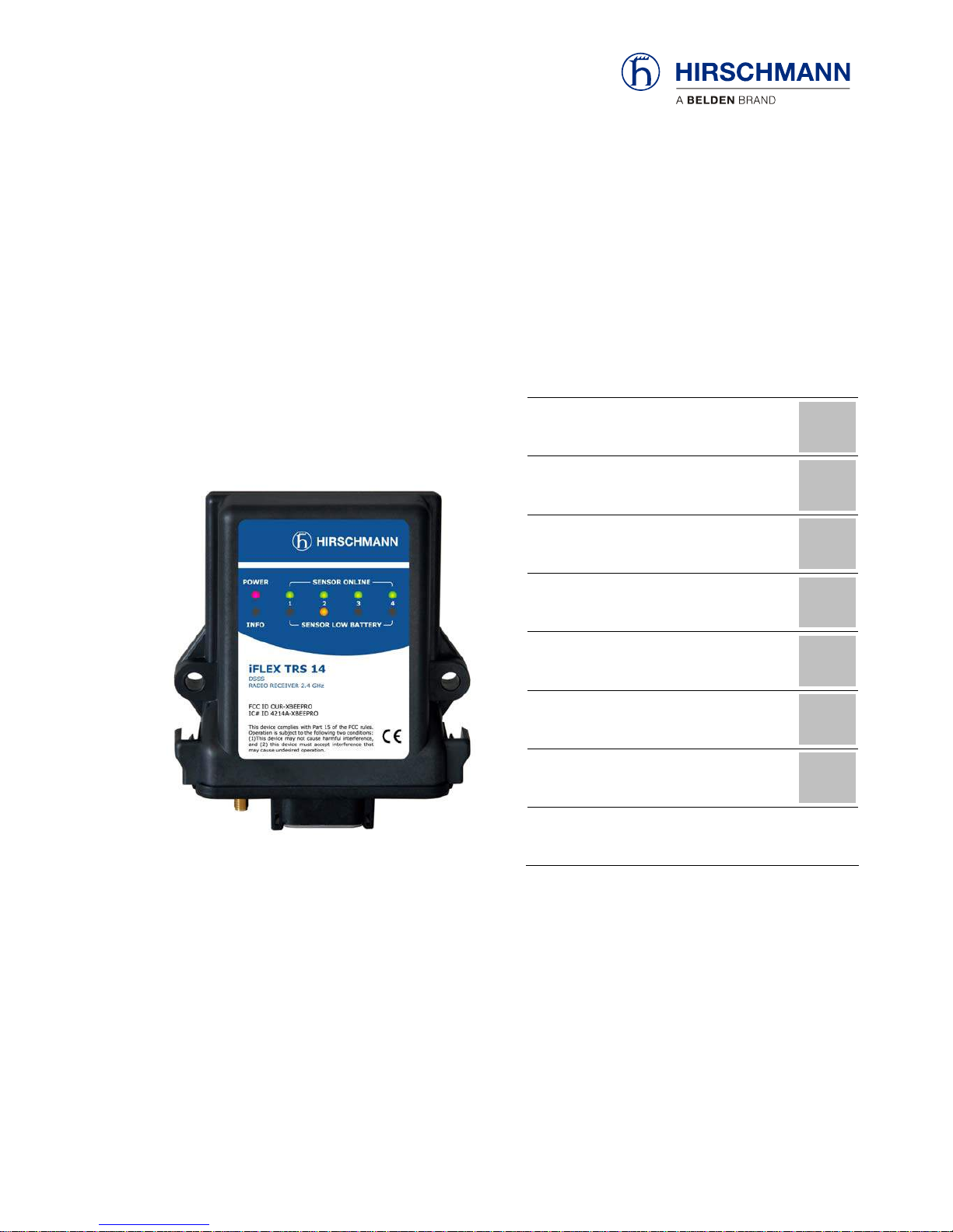
iFLEX TRS 14
Transceiver
for wireless sensors
Contents
Safety instructions
1
Product description
2
Installation
3
Commissioning
4
Configuration
5
Service and maintenance
6
Technical data
7
User manual
Issue A - 08/2010
This document has the order no.
21-810-19-0003_421830_en
Page 2

TABLE OF CONTENTS
1 Safety instructions...........................................................................................6
1.1 EU conformity declaration ............................................................................8
2 Product description .......................................................................................10
2.1 General .......................................................................................................10
2.2 Product features .........................................................................................11
2.3 Use for the intended purpose .....................................................................11
2.4 Scope of supply ..........................................................................................11
2.5 View of device.............................................................................................12
2.6 Dimensions .................................................................................................13
3 Installation.......................................................................................................14
3.1 Mounting the components ..........................................................................14
3.1.1 iFLEX TRS 14 ....................................................................................14
3.1.2 Magnetic base antenna......................................................................14
3.2 Electrical connection...................................................................................15
3.2.1 Wiring of the central connector ..........................................................16
3.2.2 Wiring of the connecting cable...........................................................16
4 Commissioning...............................................................................................17
4.1 Switching the device on..............................................................................17
4.2 Status LEDs................................................................................................19
4.3 Opening/closing the housing ......................................................................20
4.4 Preconfiguration of the output signals (current/voltage).............................22
5 Configuration..................................................................................................23
5.1 Overview of functions .................................................................................24
5.2 Registering a wireless sensor.....................................................................25
5.3 Deleting wireless sensors...........................................................................27
5.4 Setting the signal range..............................................................................28
5.5 Adjusting the zero point (load/angle sensor only) ......................................30
5.6 Erasing the EEPROM.................................................................................31
5.7 Setting the angle range (angle sensor only)...............................................32
6 Service and maintenance..............................................................................33
7 Technical data.................................................................................................34
© 2010 Hirschmann Automation and Control GmbH · Branch Office Ettlingen · E-mail: info.ecs@hirschmann.de 2/37
21-810-19-0003_421830_en (Rev A).doc / 2010-08-31 / Issue A / rk.
Page 3

Tables and illustrations
Table 1 Overview of wireless sensors ................................................................. 10
Table 2 Overview of status LED .......................................................................... 19
Table 3 Overview of signal ranges ...................................................................... 28
Figure 1: View of the iFLEX TRS 14.................................................................... 12
Figure 2: Dimensions of the iFLEX TRS 14 (with magnetic base antenna) ........13
Figure 3: Magnetic base antenna (art. no.536023) with mounted radiator..........14
Figure 4: Pin configuration of the central connector ............................................ 16
Figure 5: Wiring of the connecting cable ............................................................. 16
Figure 6: View of the programming button ..........................................................23
VERSION OVERVIEW
Issue Date Description Editor
A 2010-08-31 First issue, translation of the german original issue A Konopka
HIRSCHMANN Automation and Control GmbH
Hertzstr. 32-34, 76275 Ettlingen, phone +49 (0)7243-709-0
© 2010 Hirschmann Automation and Control GmbH · Branch Office Ettlingen · E-mail: info.ecs@hirschmann.de 3/37
21-810-19-0003_421830_en (Rev A).doc / 2010-08-31 / Issue A / rk.
Page 4

Introduction
INTRODUCTION
This manual is a component of the equipment or system supplied by Hirschmann Automation and
Control GmbH. Keep this manual in a safe place and ensure that it is available to all users.
About this manual
The contents of this manual are subject to change. Hirschmann Automation and Control GmbH
does not provide any guarantee for this material, including the associated guarantee regarding
marketability and suitability for certain intended purposes. Hirschmann Automation and Control
GmbH accepts no liability for errors in the contents of the manual or for direct or indirect damage in
connection with the provision and use of the manual.
Liability disclaimer
This manual is protected by copyright. All rights reserved. The manual may not be duplicated, reproduced or translated into another language, either wholly or partly, without the prior written permission of Hirschmann Automation and Control GmbH.
Copyright
notice
The rendition of common names, trade names, trademarks etc. in this documentation should not be
construed to mean that such names, even without special identification, are free in the sense of
trademark and trademark protection legislation and hence usable by anyone.
Trademarks
This device / system is intended exclusively for the tasks described in this manual. Any other use
shall be construed as being inappropriate. The manufacturer accepts no liability for damage caused
by inappropriate or impermissible use. This device / system may only be used if it is in perfect technical condition.
Use for the intended
purpose
Only appropriately qualified personnel may work with this device / system, i.e. persons:
Qualification of the
operating personnel
who are familiar with the operation or installation and commissioning
who know the current regulations for the prevention of accidents
© 2010 Hirschmann Automation and Control GmbH · Branch Office Ettlingen · E-mail: info.ecs@hirschmann.de 4/37
21-810-19-0003_421830_en (Rev A).doc / 2010-08-31 / Issue A / rk.
Page 5
Introduction
Marking of notices
Dangers and other important notices are marked as follows in this user manual:
WARNING
Warning of direct threat of personal injury and damage to property.
Instructions on precautions to avert the danger.
CAUTION
Warning of dangerous situations. Also warns of damage to property.
Instructions for averting the danger.
IMPORTANT
Warning of possibly damaging situation for the product.
Instructions for avoiding the possibly damaging situation.
NOTE
Usage instructions and information, but no dangerous situation.
HINT
Supplementary comments and recommendations for the user.
© 2010 Hirschmann Automation and Control GmbH · Branch Office Ettlingen · E-mail: info.ecs@hirschmann.de 5/37
21-810-19-0003_421830_en (Rev A).doc / 2010-08-31 / Issue A / rk.
Page 6
Safety instructions
1 Safety instructions
In order to avoid possible personal injuries and damage to property when using this device, it is
essential to observe the following safety instructions:
CAUTION
Danger of electrical short-circuits.
Switch off all systems before commencing with the installatio n work!
CAUTION
Danger due to the inadvertent registration of a nearby wireless sensor.
Make sure that the batteries of other wireless sensors are not changed during a registration
procedure on an iFLEX TRS 14.
IMPORTANT
Damage to the device if connected to an unsuitable power supply.
The device may only be connected to a DC voltage source of 10 V to 30 V!
IMPORTANT
Damage to the equipment due to non-compliance with the regulations for the handling of
equipment containing electrostatically sensitive devices (ESDs):
Pay attention to the following instructions if the device has to be opened during commissioning:
• Discharge yourself (e.g. by touching an earthed object) before opening the device
• Hold the printed circuit board only by the edges
• Do not touch components or connector pins or tracks
© 2010 Hirschmann Automation and Control GmbH · Branch Office Ettlingen · E-mail: info.ecs@hirschmann.de 6/37
21-810-19-0003_421830_en (Rev A).doc / 2010-08-31 / Issue A / rk.
Page 7
Safety instructions
IMPORTANT
Impairment of the system function due to the use of an unsuitable anten na radiator.
Always use the antenna radiator included in the scope of supply!
IMPORTANT
Impairment of the system function or breaching of radio transmission regulations by the use
of components or extensions not approved by the manufacturer.
Use exclusively components or extensions that are intended and approved by the manufacturer.
IMPORTANT
Possible impairment of the radio link/range in direct proximity to antenna systems with a
high HF transmission power.
The device must not be used in the direct proximity of radar systems or transmitters (e.g.
radio, TV, mobile telephone etc.) or close to power supply systems.
IMPORTANT
Damage to the device due to the penetration of water and dirt.
Never clean the device with a high pressure cleaner!
Have damage to the decorative foil repaired professionally without delay!
© 2010 Hirschmann Automation and Control GmbH · Branch Office Ettlingen · E-mail: info.ecs@hirschmann.de 7/37
21-810-19-0003_421830_en (Rev A).doc / 2010-08-31 / Issue A / rk.
Page 8

Safety instructions
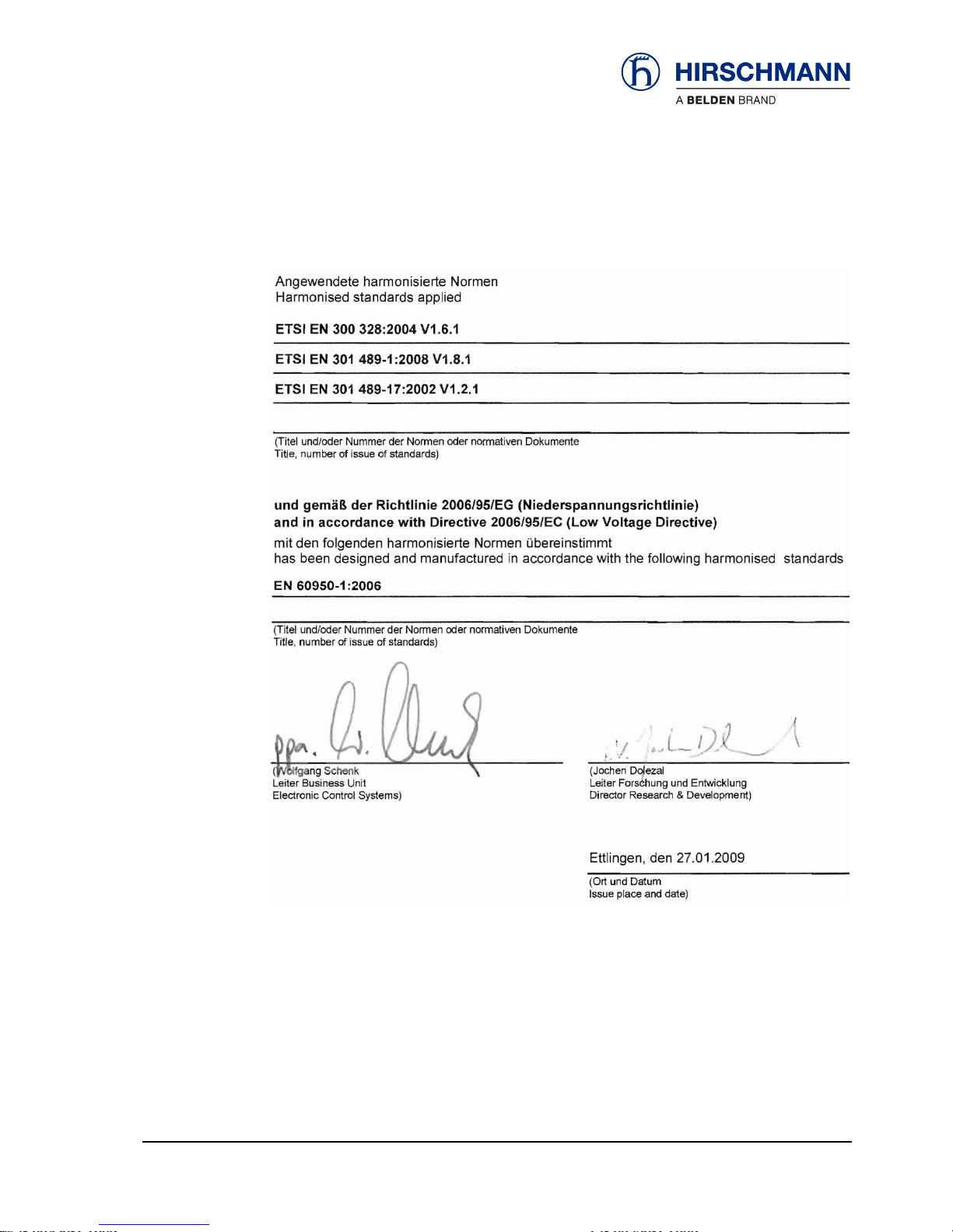
1.1 EU conformity declaration
© 2010 Hirschmann Automation and Control GmbH · Branch Office Ettlingen · E-mail: info.ecs@hirschmann.de 8/37
21-810-19-0003_421830_en (Rev A).doc / 2010-08-31 / Issue A / rk.
Page 9
Safety instructions
© 2010 Hirschmann Automation and Control GmbH · Branch Office Ettlingen · E-mail: info.ecs@hirschmann.de 9/37
21-810-19-0003_421830_en (Rev A).doc / 2010-08-31 / Issue A / rk.
Page 10

Product description
2 Product description
2.1 General
The iFLEX TRS 14 is a transceiver for the wireless coupling of wireless sensors from the Hirschmann xSENS-xxx-W1 family.
Up to 4 wireless sensors can be connected wirelessly to a single iFLEX TRS 14. The number of
wireless sensors can be extended as required by the employment of several transceivers.
How many sensors
can be connected?
All sensors from the xSENS-xxx-W1 family from Hirschmann’s extensive range of wireless sensors
can be used.
(the article numbers given on the right refer in each case to the sensors including accessories)
Application Product designation
Which wireless sen-
sors can be used?
Article no.
(set)
Load
measurement
fSENS KMD-006-W1 (up to 6 t)
Art. no. 605792
alternatively also
fSENS KMD-020-W1 (up to 20 t)
Art. no. 606345
Angle
measurement
gSENS WGF-W1 (0 to 90°)
Art. no. 608016
e.g. for boom angle measurement
or
gSENS WGS-W1 (-15 to +15°)
Art. no. 608185
for inclination measurement
Wind
measurement
iSENS WSS-W1
608179
Hoist limit
monitoring
(A2B)
iSENS HES-W1
Art. no. 608015
608180
Table 1 Overview of wireless sensors
© 2010 Hirschmann Automation and Control GmbH · Branch Office Ettlingen · E-mail: info.ecs@hirschmann.de 10/37
21-810-19-0003_421830_en (Rev A).doc / 2010-08-31 / Issue A / rk.
Page 11

Product description
2.2 Product features
The iFLEX TRS 14 is characterised by the following features:
Wireless coupling of up to four wireless sensors from the xSENS-xxx-W1 family
Registration of a wireless sensor to the receiver at the push of a button
Relay output for hoist limit signal
Four analog signal outputs (configurable for current/voltage)
Status LEDs for signalling various operating conditions
Monitoring of the battery condition of the connected wireless sensors
Self-diagnostic function
Sensor calibration by radio command
Protection class IP65, hence also suitable for outdoor use
Operating temperature -40 to +85 °C
Voltage supply 10 to 30 V DC
2.3 Use for the intended purpose
The iFLEX TRS 14 is a transceiver for the transmission of sensor data collected wirelessly from up
to four radio sensors from the xSENS-xxx-W1 family.
Configurable signal outputs make universal adaptation possible. Because of possible impairment of
radio communication/range in direct proximity to antenna systems with a high HF transmission
power, the device must not be used in the direct proximity of radar systems or transmitters (e.g.
radio, TV, mobile telephone etc.) or close to power supply systems.
2.4 Scope of supply
The scope of supply of the iFLEX TRS 14 with accessories (art. no. 608177) consists of the following parts:
iFLEX TRS 14
Magnetic base antenna with 4 m connecting cable
Antenna radiator
Connecting cable, 4,7 m, with prefabricated central plug at one end
User manual on CD
© 2010 Hirschmann Automation and Control GmbH · Branch Office Ettlingen · E-mail: info.ecs@hirschmann.de 11/37
21-810-19-0003_421830_en (Rev A).doc / 2010-08-31 / Issue A / rk.
Page 12
Product description
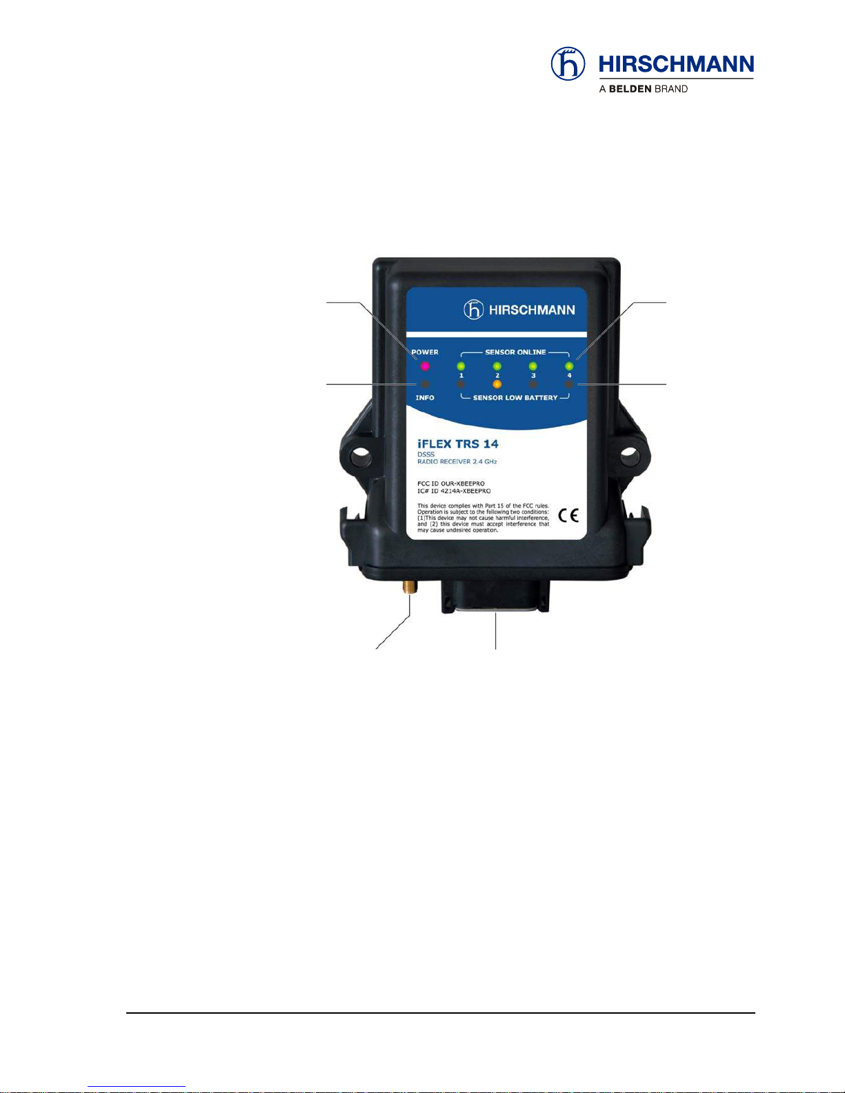
2.5 View of device
Operating
status
Indicators for
registered wireless sensors
channels 1 to 4
Indicator for
hoist limit
signal
Indicator for
weak sensor
battery
channels 1 to 4
Coaxial socket
for antenna
Central plug
Figure 1: View of the iFLEX TRS 14
© 2010 Hirschmann Automation and Control GmbH · Branch Office Ettlingen · E-mail: info.ecs@hirschmann.de 12/37
21-810-19-0003_421830_en (Rev A).doc / 2010-08-31 / Issue A / rk.
Page 13

Product description
2.6 Dimensions
Figure 2: Dimensions of the iFLEX TRS 14 (with magnetic base antenna)
© 2010 Hirschmann Automation and Control GmbH · Branch Office Ettlingen · E-mail: info.ecs@hirschmann.de 13/37
21-810-19-0003_421830_en (Rev A).doc / 2010-08-31 / Issue A / rk.
Page 14

Installation
3 Installation
3.1 Mounting the components
The iFLEX TRS 14 is supplied complete with all accessories required for operation. Mounting can
therefore be performed simply and quickly. For mounting the wireless sensors, please refer to the
instructions provided with the respective sensor.
3.1.1 iFLEX TRS 14
The iFLEX TRS 14 must be mounted in a suitable place on a sufficiently firm surface with the connections at the bottom. The device may be used both indoors and outdoors and is to be mounted
such that the LEDs are visible.
The distance between the holes in the housing is 102 mm.
3.1.2 Magnetic base antenna
Antenna radiator 2.4 GHz
Antenna base
Magnetic baseplate
Figure 3: Magnetic base antenna (art. no. 536023) with mounted radiator
First of all, screw the antenna radiator
hand tight onto the thread on the top side of the antenna
base until you feel a stop. (Remove the protective cap from the thread if necessary).
Preparation of the
antenna
The antenna has a magnetic baseplate and adheres securely to all ferromagnetic surfaces thanks
to its strong magnet.
How do I mount the
antenna?
NOTE
Optimal ranges are achieved if the antenna is aligned in accordance with the alignment of
the wireless sensor antennas and can radiate as freely as possible.
Niches or recesses are therefore less suitable as mounting locations!
© 2010 Hirschmann Automation and Control GmbH · Branch Office Ettlingen · E-mail: info.ecs@hirschmann.de 14/37
21-810-19-0003_421830_en (Rev A).doc / 2010-08-31 / Issue A / rk.
Page 15

Installation
Please follow the instructions below for laying the antenna cable:
How should the
cable be laid?
IMPORTANT
The antenna cable can be damaged if it is squeezed or kinked.
Therefore, lay the antenna cable in such a way that it is neither squeezed nor laid around
sharp edges!
IMPORTANT
The function of the antenna and hence the whole system can be impaired if a mismatch in g
antenna radiator is used.
Always use the antenna radiator contained in the scope of supply!
After laying the cable, connect the coaxial connector of the antenna to the antenna socket on the
underside of the iFLEX TRS 14. Screw the connector on hand tight.
Where is the an-
tenna
connected?
3.2 Electrical connection
Connection of the device is simple thanks to the connecting cable (4,7 m), which is prefabricated at
one end and included in the scope of supply. The open cable end is to be connected properly using
wire end ferrules. Please refer to the following illustrations for the wiring of the connecting cable and
the pin configuration of the central plug.
CAUTION
Danger of electrical short-circuits.
Switch off all systems before commencing with the installatio n work!
IMPORTANT
Damage to the device if connected to an unsuitable power supply.
The device may only be connected to a DC voltage source of 10 V to 30 V!
© 2010 Hirschmann Automation and Control GmbH · Branch Office Ettlingen · E-mail: info.ecs@hirschmann.de 15/37
21-810-19-0003_421830_en (Rev A).doc / 2010-08-31 / Issue A / rk.
Page 16

Installation
3.2.1 Wiring of the central connector
Please refer to the following illustration for the pin configuration of the connector on the underside
of the iFLEX TRS 14 (top view):
Pin 1 +VDC (10 to 30 V)
Pin 2 GND
Pin 3 Ground
Pin 4 Signal output, Sensor 1
Pin 5 Ground
Pin 6 Signal output, Sensor 2
Pin 7 Ground
Pin 8 Signal output, Sensor 3
Pin 9 not connected
Pin 10 Signal output, Sensor 4
Pin 11 Relay output, hoist limit switch:
open in hoist limit condition
+U
B
if no hoist limit condition
or if no hoist limit switch exists
Pin 12 not connected
B
Figure 4: Pin configuration of the central connector
3.2.2 Wiring of the connecting cable
The cable contained in the scope of supply is prefabricated at one end with the central plug. The
open cable end must be wired according to the following illustration. The external screen should be
connected if possible:
Length:
4,7 m
Figure 5: Wiring of the connecting cable
© 2010 Hirschmann Automation and Control GmbH · Branch Office Ettlingen · E-mail: info.ecs@hirschmann.de 16/37
21-810-19-0003_421830_en (Rev A).doc / 2010-08-31 / Issue A / rk.
Page 17

Commissioning
4 Commissioning
At least one functional wireless sensor must be available in order to commission and operate the
system.
A guide to commissioning and configuring the signal outputs of the iFLEX TRS 14 and connecting
the wireless sensors is provided below.
NOTE
During the initial commissioning and the necessary registratio n of the wireless sensors, it is
useful if these are not yet mounted, but are available close to the iFLEX TRS14.
4.1 Switching the device on
After wiring the iFLEX TRS 14, the device switches itself on as soon as the supply voltage is present. The red ‘Power’ LED lights up. After switching on, the system begins with a self-diagnostic
routine.
How is the device
switched on?
The self-diagnosis takes approx. 3 seconds. During these tests the ‘Info’ LED additionally flashes
and the remaining LEDs light up in succession with a test pattern:
How long does the
self-diagnosis take?
LED key: off: lights: flashes slowly: flashes rapidly:
If no wireless sensors have been registered yet, only the ‘Power’ LED should be lit after completion
of the self-diagnosis:
How can I tell
whether the device is
working correctly?
If wireless sensors have already been registered, the ‘Online’ LED of the respective channel additionally lights up, indicating that the radio link has been established.
© 2010 Hirschmann Automation and Control GmbH · Branch Office Ettlingen · E-mail: info.ecs@hirschmann.de 17/37
21-810-19-0003_421830_en (Rev A).doc / 2010-08-31 / Issue A / rk.
Page 18

Commissioning
If a ‘Low Battery’ LED lights up, this means that the battery set in the respective wireless sensor is
exhausted (remaining capacity < 6,5 %) and must be replaced as soon as possible.
Which does it mean
when the ‘Low Batt’
LED lights up?
If the ‘INFO’ LED lights up, this means that one of the connected wireless hoist limit switches has
reported ‘hoist limit’. At the same time, the relay contact opens and there is no voltage at the signal
output. The LED may also light up briefly after the iFLEX TRS 14 is switched on, until the radio link
to the registered hoist limit switches has been established. If the LED remains lit, this means that
the radio link to a registered wireless hoist limit switch is interrupted. In this case the ‘Online’ LED
assigned to the respective channel also flashes.
What does it mean
when the ‘Info’ LED
lights up?
The flashing of an ‘ONLINE’ LED after conclusion of the self-diagnosis means that either the radio
link with the registered wireless sensor on the indicated channel is interrupted, or, in conjunction
with the lighting up of the ‘INFO’ LED, that a wireless hoist limit switch on the indicated channel is in
‘sleep’ mode. This mode is activated automatically if the hoist limit switch remains in the hoist limit
condition for a lengthy period of time. This function serves to reduce the power requirement of the
hoist limit switch. The function is reset automatically upon the next switching of the hoist limit
switch.
What does it mean
when an ‘Online’
LED flashes?
NOTE
If the link to a wireless sensor is interrupted, rectify the fault first before putting the system
into operation.
© 2010 Hirschmann Automation and Control GmbH · Branch Office Ettlingen · E-mail: info.ecs@hirschmann.de 18/37
21-810-19-0003_421830_en (Rev A).doc / 2010-08-31 / Issue A / rk.
Page 19

Commissioning
4.2 Status LEDs
There are 10 LEDs on the front panel of the device, which indicate the status of various operating
conditions.
The meaning of the signals can be taken from the table below. The signals apply only to normal
operation; deviating signals apply to programming mode:
off:
lights:
flashes:
No supply
voltage present
Supply voltage is
present
Hoist limit switch has
triggered
or
radio link to a wire-
less hoist limit switch
interrupted
During the system diagnosis
No sensor
registered to
this channel
Sensor registered to
this channel and
ready for operation
During the registration of new
wireless sensors
or
hoist limit switch on the indi-
cated channel is in ‘sleep’ mode
or
link with the sensor on the indi-
cated channel is interrupted
Batteries of the wire-
less sensor on this
channel are almost
exhausted!
(capacity < 6.5 %)
Replace the batter-
ies soon!
Table 2 Overview of status LED
© 2010 Hirschmann Automation and Control GmbH · Branch Office Ettlingen · E-mail: info.ecs@hirschmann.de 19/37
21-810-19-0003_421830_en (Rev A).doc / 2010-08-31 / Issue A / rk.
Page 20

Commissioning
4.3 Opening/closing the housing
It is necessary to open the housing of the iFLEX TRS 14 in order to configure the output signals
and the radio link by means of the programming button and jumpers as described below.
First of all, disconnect the device from the power supply by pulling out the central plug.
IMPORTANT
Damage to the equipment due to non-compliance with the regulations for the handling of
equipment containing electrostatically sensitive devices (ESDs):
Pay attention to the following instructions if the device has to be opened during commissioning:
• Discharge yourself (e.g. by touching an earthed object) before opening the device
• Hold the printed circuit board only by the edges
• Do not touch components or connector pins or tracks
Follow the procedure described below to open the housing:
Open the housing
HINT
A flat-blade screwdriver with a blade width of 4.5 - 5.5 mm is best suited for opening the
housing.
▲ 1. By means of a slight twisting movement of the
screwdriver, press the latches (on both sides of the
housing at the rear) carefully towards the housing
and in this way unlock the circuit board
▲ 2. The housing seal will be visible if the circuit
board has been unlocked correctly
© 2010 Hirschmann Automation and Control GmbH · Branch Office Ettlingen · E-mail: info.ecs@hirschmann.de 20/37
21-810-19-0003_421830_en (Rev A).doc / 2010-08-31 / Issue A / rk.
Page 21

Commissioning
▲ 3. Carefully pull the circuit board out of the
housing
▲ 4. View of the programming button and the
jumpers (in this case for channel 1) on the circuit
board
Follow the procedure described below to close the housing:
Close the housing
▲ 1. Carefully slide the circuit board into the guide
rails in the housing.
Make sure that the foam strip is positioned as
shown.
▲ 2. Lock the circuit board by applying strong pres-
sure to the underside of the housing (clearly audible
click at both sides).
© 2010 Hirschmann Automation and Control GmbH · Branch Office Ettlingen · E-mail: info.ecs@hirschmann.de 21/37
21-810-19-0003_421830_en (Rev A).doc / 2010-08-31 / Issue A / rk.
Page 22

Commissioning
4.4 Preconfiguration of the output signals (current/voltage)
The analog signal outputs (channels 1 to 4) are commonly preconfigured in the factory as 4-20 mA
current outputs. If necessary the signal outputs can also be commonly configured as voltage outputs.
NOTE
The signal outputs (channels 1 to 4) can be commonly configured either as current outputs
or as voltage outputs. A mixed configuration is not possible!
The conversion is made by changing the jumpers on the circuit board and subsequently selecting
the signal range via the programming button. These elements are only accessible after opening
the device. (See chapter
4.3)
How can the outputs
be configured as
voltage outputs?
The jumpers for configuring the output signals are located above the LEDs for the corresponding
channels 1 - 4:
Jumper
Now set the jumpers identically for each channel according to the sketch below:
▲ Jumper setting
for current outputs
(standard)
▲ Jumper setting
for voltage outputs
NOTE
If you have configured the signal outputs as voltage outputs, it is also necessary to select
the signal range. (See chapter 5.4)
© 2010 Hirschmann Automation and Control GmbH · Branch Office Ettlingen · E-mail: info.ecs@hirschmann.de 22/37
21-810-19-0003_421830_en (Rev A).doc / 2010-08-31 / Issue A / rk.
Page 23

Configuration
5 Configuration
Wireless sensors are registered or deleted and further device configuration functions are performed
by pressing the programming button for a certain length of time whilst observing the visual confirmation via the LEDs.
The programming button is located inside the housing of the device and is only accessible after
opening the housing. (To open the housing, see chapter
4.3)
Programming
button
Figure 6: View of the programming button
When doing this, pay attention to the safety instructions for the handling of subassemblies containing electrostatically sensitive devices (ESDs). (See safety instructions in Chapter
1)
In order to select a certain function, press and hold the programming button until the desired function is signalled by the LEDs. Then release the programming button. Distinction must thereby be
made between flashing and steadily lit LEDs.
The programming cycle is circular and requires approx. 71 seconds for a complete circuit.
How are the func-
tions selected?
In order to exit from the programming cycle, you can either go through the cycle until the end or
briefly remove the central plug. Settings that have already been made will be retained.
How can I exit from
the programming
mode?
An overview of the functions that can be called via the programming button can be found below:
© 2010 Hirschmann Automation and Control GmbH · Branch Office Ettlingen · E-mail: info.ecs@hirschmann.de 23/37
21-810-19-0003_421830_en (Rev A).doc / 2010-08-31 / Issue A / rk.
Page 24

Configuration
5.1 Overview of functions
Function selection Display from to
Register wireless sensor
… to channel 1
LED 1, green, flashes
3 6
… to channel 2 LED 2, green, flashes 6 9
… to channel 3 LED 3, green, flashes 9 12
… to channel 4
LED 4, green, flashes 12 15
Delete wireless sensor
… from channel 1
LED 1, green, lights steadily
16 19
… to channel 2 LED 2, green, lights steadily 19 22
… to channel 3 LED 3, green, lights steadily 22 25
… to channel 4
LED 4, green, lights steadily 25 28
Set signal range A
(for all outputs)
All green LEDs flash
29 32
signal range B… all green LEDs light steadily 33 36
signal range C … All yellow LEDs flash 37 40
signal range D …
all yellow LEDs light steadily 40 43
Sensor calibration
(load/angle)
… on channel 1
LED 1, green and yellow, flash
43 46
… to channel 2 LED 2, green and yellow, flash 46 49
… to channel 3 LED 3, green and yellow, flash 50 53
… to channel 4
LED 4, green and yellow, flash 53 56
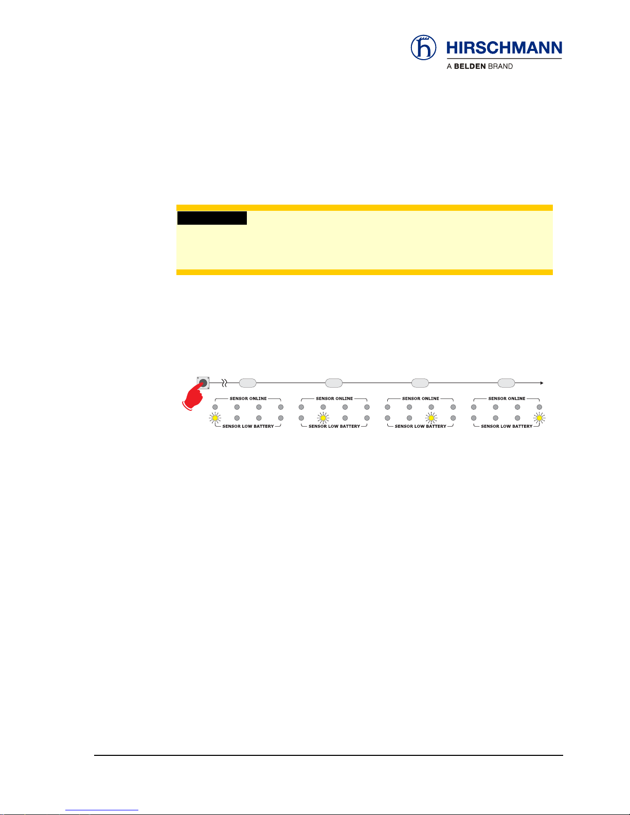
Erase EEPROM LED 1, yellow, flashes 56 59
Set angle range of angle
sensor
…to -15° to 15°(gSENS WGS)
LED 2, yellow, flashes
59 63
…to 0° to 90°(gSENS WGF) LED 3, yellow, flashes 63 66
- no function assigned -
LED 4, yellow, flashes 67 70
Menu end All LEDs off 71
A detailed description of the functions with which the device can be configured is provided below.
© 2010 Hirschmann Automation and Control GmbH · Branch Office Ettlingen · E-mail: info.ecs@hirschmann.de 24/37
21-810-19-0003_421830_en (Rev A).doc / 2010-08-31 / Issue A / rk.
Page 25

Configuration
5.2 Registering a wireless sensor
Every wireless sensor to be used (maximum 4) must be registered once to the iFLEX TRS 14
for operation.
What needs to be
observed?
The common use of angle sensors gSENS WGF-W1 and gSENS WGF-W1 is not possible.
The wireless sensor does not need to be registered again following a battery change.
Re-registration is necessary after exchanging a wireless sensor.
Wireless sensors that are not to be used any longer must be deleted and deactivated by re-
moving the batteries.
CAUTION
Danger due to the inadvertent registration of a nearby wireless sensor.
Make sure that the batteries of other wireless sensors are not changed during a registration
procedure on an iFLEX TRS 14.
Follow the procedure described below to register a wireless sensor.
The wireless sensor should be no more than 1 metre away from the iFLEX TRS 14 during the
registration phase.
Connect the iFLEX TRS 14 to the power supply again. (See also Chapter 4.1)
HINT
Keep a fresh set of batteries at the ready for the registration.
▲ 1. First of all, open the battery compartment of
the wireless sensor to be registered by undoing the
cover screws and removing the cover of the battery
compartment.
▲ 2. Remove the batteries
© 2010 Hirschmann Automation and Control GmbH · Branch Office Ettlingen · E-mail: info.ecs@hirschmann.de 25/37
21-810-19-0003_421830_en (Rev A).doc / 2010-08-31 / Issue A / rk.
Page 26

Configuration
3s 6s 9s 12s
anmelden an Kanal 1 anmelden an Kanal 2 anmelden an Kanal 3 anmelden an Kanal 4
▲ 3. Press and hold the programming button of the iFLEX TRS14 until:
- Online LED1 flashes (for the registration of a wireless sensor to channel 1)
- Online LED2 flashes (for the registration of a wireless sensor to channel 2)
- Online LED3 flashes (for the registration of a wireless sensor to channel 3)
- Online LED4 flashes (for the registration of a wireless sensor to channel 4)
and then release the button.
▲ 4. Now insert the batteries into the battery com-
partment of the wireless sensor to be registered,
observing the correct polarity.
▲ 5. Observe the LED on the underside of the
housing. This should light up with short pulses. Now
fit the cover of the battery compartment.
▲ 6. The wireless sensor is registered correctly if
the respective Online LED lights steadily (in this
case e.g. channel 1).
If a wireless hoist limit switch has been registered:
Now pull on the rope of the wireless hoist limit switch
for 5 secs. The system is working perfectly if the
‘INFO’ LED extinguishes within this time. The wireless sensor is now ready to be mounted.
© 2010 Hirschmann Automation and Control GmbH · Branch Office Ettlingen · E-mail: info.ecs@hirschmann.de 26/37
21-810-19-0003_421830_en (Rev A).doc / 2010-08-31 / Issue A / rk.
Page 27

Configuration
5.3 Deleting wireless sensors
Wireless sensors that are not to be used any longer must be deleted and deactivated by removing
the batteries.
Follow the procedure described below to delete a wireless sensor.
1. Open the housing of the iFLEX TRS 14 as described in chapter 4.3.
16s 19s 22s 25s
abmelden von Kanal 1 abmelden von Kanal 2 abmelden von Kanal 3 abmelden von Kanal 4
▲ 2. Press and hold the programming button of the iFLEX TRS14 until:
- Online LED1 lights steadily (for the deletion of a wireless sensor from channel 1)
- Online LED2 lights steadily (for the deletion of a wireless sensor from channel 2)
- Online LED3 lights steadily (for the deletion of a wireless sensor from channel 3)
- Online LED4 lights steadily (for the deletion of a wireless sensor from channel 4)
and then release the button.
The wireless sensor is deleted as soon as the respective ‘Online’ LED has extinguished.
© 2010 Hirschmann Automation and Control GmbH · Branch Office Ettlingen · E-mail: info.ecs@hirschmann.de 27/37
21-810-19-0003_421830_en (Rev A).doc / 2010-08-31 / Issue A / rk.
Page 28

Configuration
5.4 Setting the signal range
After preselecting the signal outputs (current/voltage) via the jumpers (see chapter 4.4), it is then
also necessary to select the signal range.
An overview of the possible signal outputs for the different types of sensor can be found in the table
below. The signal outputs are all preconfigured in the factory to signal range B (current 4 to 20mA).
Select a desired signal range and note the assigned letter A to D
Signal range Type of sensor Output signal Error from
fSENS KMD-xxx-W1 load cell 0…2,5V [0…45000 lb] 5V
gSENS WGF-W1 angle sensor -3,125…-1,875V [0…90°] -3,14V
gSENS WGS-W1 inclination sensor 0,5…4,5V [-15…+15°] 5V
A
(voltage)
iSENS WSS-W1 anemometer 1,8…9,0V [0…50 mph] 9V
fSENS KMD-xxx-W1 load cell 4…20mA [0…45000 lb] 24mA
gSENS WGF-W1 angle sensor 20…4mA [0…90°] 24mA
gSENS WGS-W1 inclination sensor 4…20mA [-15…+15°] 24mA
B
(current)
standard
iSENS WSS-W1 anemometer 4…20 mA [0…50 mph] 24mA
fSENS KMD-xxx-W1 load cell 1,8…9,0V [0…45000 lb] 9V
gSENS WGF-W1 angle sensor 1,8…9,0V [0…90°] 9V
gSENS WGS-W1 inclination sensor (not defined) -
C
(voltage)
iSENS WSS-W1 anemometer 1,8…9,0V [0…50 mph] 9V
fSENS KMD-xxx-W1 load cell 0…2,5V [0…45000 lb] 5V
gSENS WGF-W1 angle sensor +3,125…+1,875V [0…90°] 3,14V
gSENS WGS-W1 inclination sensor (not defined) -
D
(voltage)
iSENS WSS-W1 anemometer 1,8…9,0V [0…50 mph] 9V
Table 3 Overview of signal ranges
Conversion: 1 lb(US) = 0,453kg 1 mph = 1,61 km/h
© 2010 Hirschmann Automation and Control GmbH · Branch Office Ettlingen · E-mail: info.ecs@hirschmann.de 28/37
21-810-19-0003_421830_en (Rev A).doc / 2010-08-31 / Issue A / rk.
Page 29

Configuration
Follow the procedure described below to set the signal range.
1. Open the housing of the iFLEX TRS 14 as described in chapter 4.3.
29s 33s 37s 40s
Auswahl Signalbereich A Auswahl Signalbereich B Auswahl Signalbereich C Auswahl Signalbereich D
▲ 2. Press and hold the programming button of the iFLEX TRS14 until:
- all green LEDs flash (for signal range A)
- all green LEDs light steadily (for signal range B)
- all yellow LEDs flash (for signal range C)
- all yellow LEDs light steadily (for signal range D)
and then release the button.
The selected signal range is set as soon as the button is released.
© 2010 Hirschmann Automation and Control GmbH · Branch Office Ettlingen · E-mail: info.ecs@hirschmann.de 29/37
21-810-19-0003_421830_en (Rev A).doc / 2010-08-31 / Issue A / rk.
Page 30

Configuration
5.5 Adjusting the zero point (load/angle sensor only)
If load and angle sensors are connected, this function can be used to make subsequent small corrections to the zero point.
Follow the procedure described below in order to adjust the zero point.
1. Open the housing of the iFLEX TRS 14 as described in chapter 4.3.
43s 46s 50s 53s
abgleichen Sensor an Kanal 1 abgleichen Sensor an Kanal 2 abgleichen Sensor an Kanal 3 abgleichen Sensor an Kanal 4
▲ 2. Press and hold the programming button of the iFLEX TRS14 until:
- green and yellow LED1 flash (for adjustment of a sensor on channel 1)
- green and yellow LED2 flash (for adjustment of a sensor on channel 2)
- green and yellow LED3 flash (for adjustment of a sensor on channel 3)
- green and yellow LED4 flash (for adjustment of a sensor on channel 4)
and then release the button. The previously flashing LEDs are now lit steadily.
The device remains in the ‘zero point adjustment’ mode.
3. Now press the programming button of the iFLEX TRS14 again, several times if necessary, until:
- the INFO LED lights up (for adjustment in the positive direction)
- the INFO LED extinguishes (for adjustment in the negative direction)
and keep the button depressed until the desired zero point is reached.
The ‘zero point adjustment’ mode can only be terminated by disconnecting the central plug.
The previously set values thereby remain stored.
© 2010 Hirschmann Automation and Control GmbH · Branch Office Ettlingen · E-mail: info.ecs@hirschmann.de 30/37
21-810-19-0003_421830_en (Rev A).doc / 2010-08-31 / Issue A / rk.
Page 31
Configuration
5.6 Erasing the EEPROM
Using this function, all stored registration and configuration data can be deleted and the factory
settings restored.
IMPORTANT
Danger due to inadvertent deletion of all registration and configuration data!
Only use this function if you really want to delete all configuration data!
Follow the procedure described below in order to erase the EEPROM:
1.
Open the housing of the iFLEX TRS 14 as described in chapter 4.3.
56s 59s 63s 67s
EEProm löschen Winkelbereich -15...+15° Winkelbereich 0...90° (keine Bedeutung)
▲ 2. Press and hold the programming button of the iFLEX TRS14 until:
- the yellow LED 1 flashes
and then release the button.
The EEPROM is erased as soon as the button is released.
© 2010 Hirschmann Automation and Control GmbH · Branch Office Ettlingen · E-mail: info.ecs@hirschmann.de 31/37
21-810-19-0003_421830_en (Rev A).doc / 2010-08-31 / Issue A / rk.
Page 32

Configuration
5.7 Setting the angle range (angle sensor only)
If an angle sensor is connected, this function is used to define the type of sensor being used.
Follow the procedure described below in order to adjust the angle range.
1. Open the housing of the iFLEX TRS 14 as described in chapter 4.3.
56s 59s 63s 67s
EEProm löschen Winkelbereich -15...+15° Winkelbereich 0...90° (keine Bedeutung)
▲ 2. Press and hold the programming button of the iFLEX TRS14 until:
- the yellow LED 2 flashes (for selection of angle range -15 to +15°, gSENS WGS-W1)
- the yellow LED 3 flashes (for selection of angle range 0 to +90°, gSENS WGF-W1)
and then release the button.
The angle range is set as soon as the button is released.
© 2010 Hirschmann Automation and Control GmbH · Branch Office Ettlingen · E-mail: info.ecs@hirschmann.de 32/37
21-810-19-0003_421830_en (Rev A).doc / 2010-08-31 / Issue A / rk.
Page 33

Service and maintenance
6 Service and maintenance
The iFLEX TRS 14 transceiver does not contain any serviceable parts. The micro-fuse inside the
device is self-resetting and therefore does not need to be exchanged. If you notice malfunctions,
you should switch the device off and have it checked and, if necessary, repaired immediately by an
authorised Hirschmann service partner.
Clean the surface of the equipment occasionally with a damp cloth using a mild cleaning agent.
However, you should never use abrasive or alcohol-based cleaning agents, as these can damage
the housing or the front foil!
IMPORTANT
Damage to the front foil can lead to the penetration of moisture and dirt into the interior of
the device.
Never clean the device with a high pressure cleaner! Have damage to th e fro nt foil rep aired
professionally without delay!
Keep the contact area of the device plug and the antenna connector clean and occasionally check
that the connections are tight.
Occasionally check the connecting cable and antenna cable as well as the antenna itself. If parts
are damaged, these must be repaired properly or replaced immediately.
© 2010 Hirschmann Automation and Control GmbH · Branch Office Ettlingen · E-mail: info.ecs@hirschmann.de 33/37
21-810-19-0003_421830_en (Rev A).doc / 2010-08-31 / Issue A / rk.
Page 34

Technical data
7 Technical data
Article designation iFLEX TRS 14
Article number 608177 (complete with accessories, see scope of supply)
Operating voltage 10 - 30 V DC
Fuse Self-resetting internal fuse, 500 mA
Transmission frequency 2.45 GHz, ISM band, licence-free and exempt from duty
IEEE 802.15.4 standard, DSSS /OQPSK modulated
Class1 radio system in accordance with FTEG and 1999/5/EC
(R&TTE)
Antenna 2.4 GHz, with magnetic base and screwed on antenna radiator,
4m connecting cable, RP-SMA plug
Range approx. 300 m (depending upon environmental conditions)
CE conformity ETSI EN 300 328
ETSI EN 301 489-1
ETSI EN 300 489-17
EN 60950-1
FCC conformity FCC 47 CFR Part 15, Radio Frequency Devices, Subpart B
Control elements 1 programming button (inside the device),
jumpers for the configuration of the signal outputs
Displays 10 Status LEDs for signalling various operating conditions
Electrical connection Central connector (German) 12-pole (on underside of device)
Signal outputs 4 analog outputs,
commonly configurable for current/voltage,
signal range commonly adjustable
1 relay contact,
switches to +U
b
when hoist limit is triggered
Antenna connection RP-SMA, coaxial (on the underside of the device)
Dimensions H 134 mm x W 118,2 mm x D 36,3 mm
Weight 0,258 kg (device only)
Distance between mounting holes 102,1 mm
Operating temperature range -40 ºC to +85 ºC
Storage temperature range -50 ºC to +85 ºC
Protection class IP 65
Scope of supply iFLEX TRS 14 with accessories:
- Magnetic base antenna with 4 m connecting cable
- Antenna radiator 2.4 GHz band
- Connecting cable, 4.5 m, partly prefabricated
- User manual on CD
© 2010 Hirschmann Automation and Control GmbH · Branch Office Ettlingen · E-mail: info.ecs@hirschmann.de 34/37
21-810-19-0003_421830_en (Rev A).doc / 2010-08-31 / Issue A / rk.
Page 35

Feedback
Feedback
What is your opinion about this manual? We always try to describe the products fully in our manuals, as well as providing important background knowledge to ensure trouble-free operation.
We take the task of continuous improvement and reduction of errors very seriously. Your comments
and suggestions help us to increase the quality and level of information for this document.
Your assessment of this manual:
excellent good satisfactory so-so poor
Accuracy O O O O O
Readability O O O O O
Ccomprehensibility O O O O O
Examples O O O O O
Structure / Layout O O O O O
Completeness O O O O O
Illustrations / Images O O O O O
Drawings, Diagrams O O O O O
Tables O O O O O
Did you discover errors in this manual?
If so, on which side?
© 2010 Hirschmann Automation and Control GmbH · Branch Office Ettlingen · E-mail: info.ecs@hirschmann.de 35/37
21-810-19-0003_421830_en (Rev A).doc / 2010-08-31 / Issue A / rk.
Page 36

Feedback
Suggestions for improvement and additional information:
General comments:
Sender:
Company / Department
Name / Phone
Street
Zip code / City
Date / Signature
Dear user,
please complete and return both pages of this feedback:
via fax to: +49 (0)7243 709 3222
via mail to: Hirschmann Automation and Control GmbH
Documentation
Hertzstr. 32-34
76275 Ettlingen / Germany
Thank you !
© 2010 Hirschmann Automation and Control GmbH · Branch Office Ettlingen · E-mail: info.ecs@hirschmann.de 36/37
21-810-19-0003_421830_en (Rev A).doc / 2010-08-31 / Issue A / rk.
Page 37

Notes
© 2010 Hirschmann Automation and Control GmbH · Branch Office Ettlingen · E-mail: info.ecs@hirschmann.de 37/37
21-810-19-0003_421830_en (Rev A).doc / 2010-08-31 / Issue A / rk.
 Loading...