

Page 1
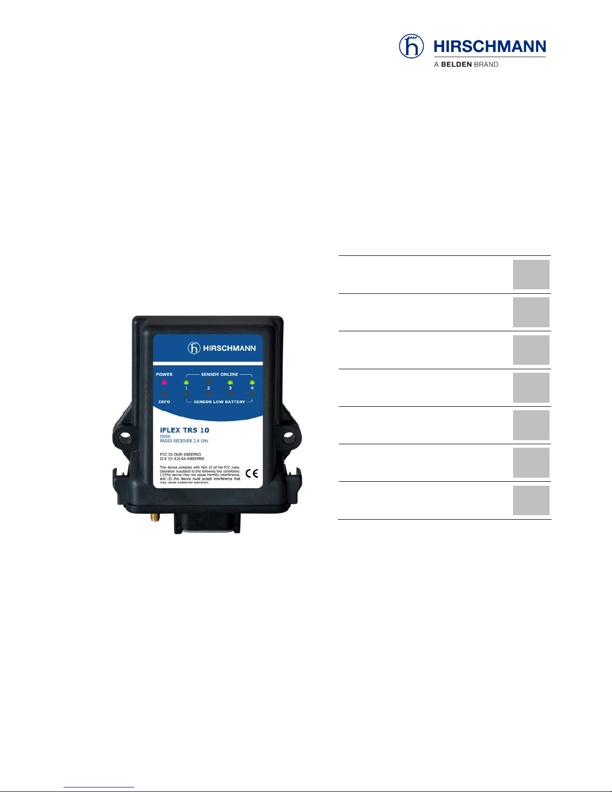
iFLEX TRS 10
CAN Transceiver
for wireless sensors
Contents
Safety instructions
1
Product description
2
Installation
3
Commissioning
4
Service and maintenance
5
Technical data
6
Appendix
7
User manual
Issue B - 08/2011
This document has the order no.
21-810-19-0001_421826_en
Page 2

TABLE OF CONTENTS
1 Safety instructions ...........................................................................................6
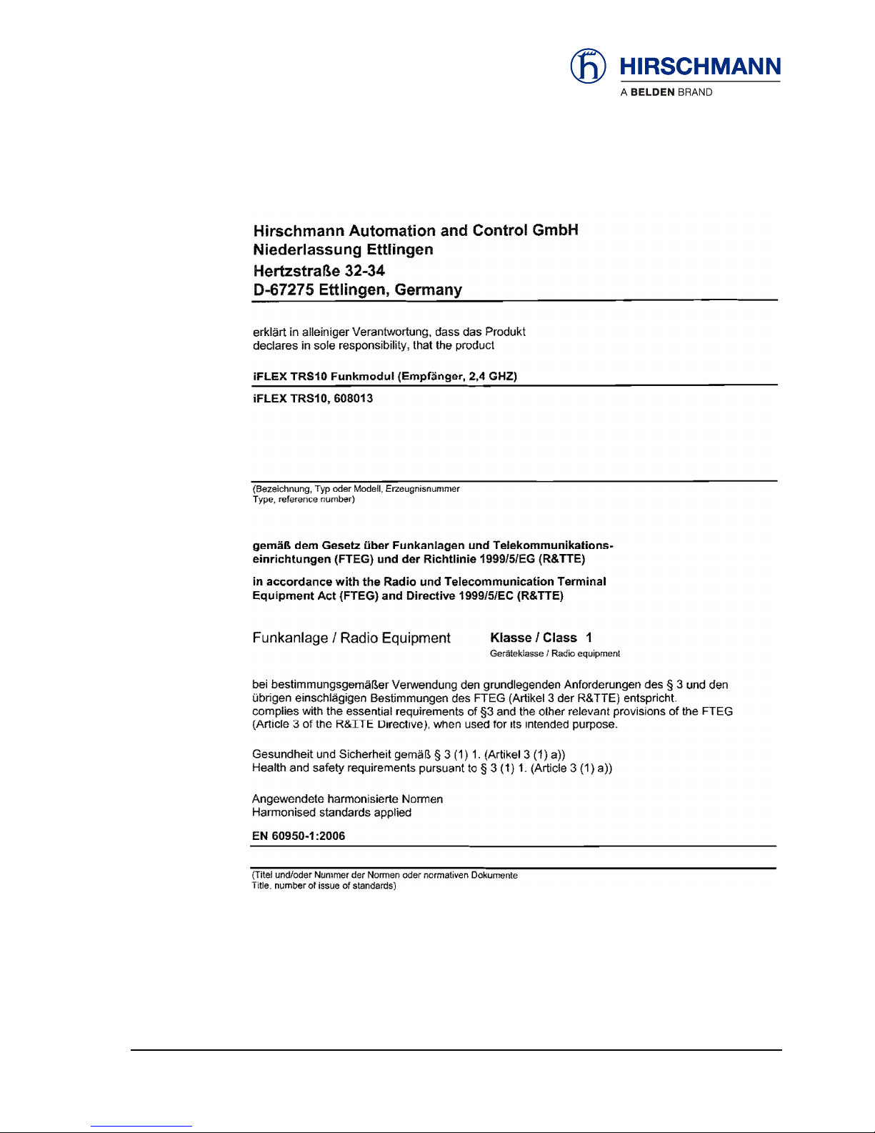
1.1 EU conformity declaration ............................................................................7
2 Product description..........................................................................................9
2.1 General .........................................................................................................9
2.2 Product features .........................................................................................10
2.3 Use for the intended purpose .....................................................................10
2.4 Scope of supply ..........................................................................................10
2.5 View of device.............................................................................................11
2.6 Dimensions .................................................................................................12
3 Installation.......................................................................................................13
3.1 Mounting the components ..........................................................................13
3.1.1 iFLEX TRS 10 ....................................................................................13
3.1.2 Short Antenna ....................................................................................13
3.1.3 Magnetic base antenna......................................................................13
3.2 Electrical connection...................................................................................14
3.2.1 Wiring of the central connector ..........................................................15
3.2.2 Wiring of the connecting cable...........................................................15
4 Commissioning...............................................................................................16
4.1 Adding a Wireless Sensor ..........................................................................16
4.2 Status LEDs................................................................................................19
4.3 Troubleshooting ..........................................................................................20
5 Service and maintenance ..............................................................................21
6 Technical data.................................................................................................22
7 Appendix .........................................................................................................23
7.1 Object listing table ......................................................................................23
7.2 Wiring of the adaptor cable for PCAN-USB................................................25
7.3 List of tables and illustrations .....................................................................25
© 2010 Hirschmann Automation and Control GmbH · Branch Office Ettlingen · E-mail: info.ecs@belden.com 2/29
21-810-19-0001_421826_en_Rev_B.doc / 2011-08-09 / Issue B / rk, kg.
Page 3

© 2010 Hirschmann Automation and Control GmbH · Branch Office Ettlingen · E-mail: info.ecs@belden.com 3/29
21-810-19-0001_421826_en_Rev_B.doc / 2011-08-09 / Issue B / rk, kg.
VERSION OVERVIEW
Issue Date Description Editor
A 2010-06-29 Translation of German original issue A (2010-06-29) Konopka
B 2011-08-08 Made changes requested by HAC – Chambersburg
ECN 11-169
Gase
HIRSCHMANN Automation and Control GmbH
Hertzstr. 32-34, 76275 Ettlingen, phone +49 (0)7243-709-0
Page 4

Introduction
INTRODUCTION
This manual is a component of the equipment or system supplied by Hirschmann Automation and
Control GmbH. Keep this manual in a safe place and ensure that it is available to all users.
About this manual
T
he contents of this manual are subject to change. Hirschmann Automation and Control GmbH
does not provide any guarantee for this material, including the associated guarantee regarding
marketability and suitability for certain intended purposes. Hirschmann Automation and Control
GmbH accepts no liability for errors in the contents of the manual or for direct or indirect damage in
connection with the provision and use of the manual.
Liability disclaimer
T
his manual is protected by copyright. All rights reserved. The manual or any of its parts may not
be duplicated, reproduced or translated into another language, either partially or completely, without
the prior written permission of Hirschmann Automation and Control GmbH.
Copyright
notice
T
he rendition of common names, trade names, trademarks etc. in this documentation should not be
construed to mean that such names, even without special identification, are free in the sense of
trademark and trademark protection legislation and hence usable by anyone.
Trademarks
This device / system is intended exclusively for the tasks described in this manual. Any other use
shall be construed as being inappropriate. The manufacturer accepts no liability for damage caused
by inappropriate or impermissible use. This device / system may only be used if it is in perfect technical condition.
Use for the intended
purpose
Onl
y appropriately qualified personnel may work with this device / system, i.e. persons:
Qualification of the
operating personnel
w
ho are familiar with the operation or installation and commissioning
who know the current regulations used to prevent accidents
© 2010 Hirschmann Automation and Control GmbH · Branch Office Ettlingen · E-mail: info.ecs@belden.com 4/29
21-810-19-0001_421826_en_Rev_B.doc / 2011-08-09 / Issue B / rk, kg.
Page 5
Introduction
© 2010 Hirschmann Automation and Control GmbH · Branch Office Ettlingen · E-mail: info.ecs@belden.com 5/29
Notification Symbols
Dangers and other important notices are marked as follows in this user manual:
21-810-19-0001_421826_en_Rev_B.doc / 2011-08-09 / Issue B / rk, kg.
WARNING
Warning of direct threat of personal injury and damage to property.
Provides instructions on precautions to avoid danger.
CAUTION
Warning of dangerous situations. Also warns of damage to property.
Provides instructions on precautions to avoid danger.
IMPORTANT
Warning of a possibly damaging situation for the product.
Provides instructions for avoiding the possibly damaging situation.
NOTE
Usage instructions and information
HINT
Supplementary comments and recommendations for the user
Page 6

Safety instructions
1 Safety instructions
In order to avoid possible personal injuries and damage to property when using this device, it is
essential to observe the following safety instructions:
CAUTION
Danger of electrical short-circuits.
Switch off all systems before commencing with the installation work!
IMPORTANT
Damage to the device can occur due to the penetration of water and dirt.
Never clean the device with a high pressure cleaner!
Have damage to the decorative foil repaired professionally without delay!
IMPORTANT
Damage to the device can occur if it is connected to an unsuitable power supply.
The device may only be connected to a DC voltage source of 10 V to 30 V!
IMPORTANT
Impairment of the system function or breaching of radio transmission regulations by the use
of components or extensions is not approved by the manufacturer.
Only use components or extensions that are approved by the manufacturer.
IMPORTANT
There is a possible impairment of the radio link/range when they are in direct proximity to
antenna systems with a high HF transmission power.
The device must not be used in the direct proximity of radar systems or transmitters (e.g.
radio, TV, mobile telephone etc.) or close to power supply systems.
© 2010 Hirschmann Automation and Control GmbH · Branch Office Ettlingen · E-mail: info.ecs@belden.com 6/29
21-810-19-0001_421826_en_Rev_B.doc / 2011-08-09 / Issue B / rk, kg.
Page 7
Safety instructions
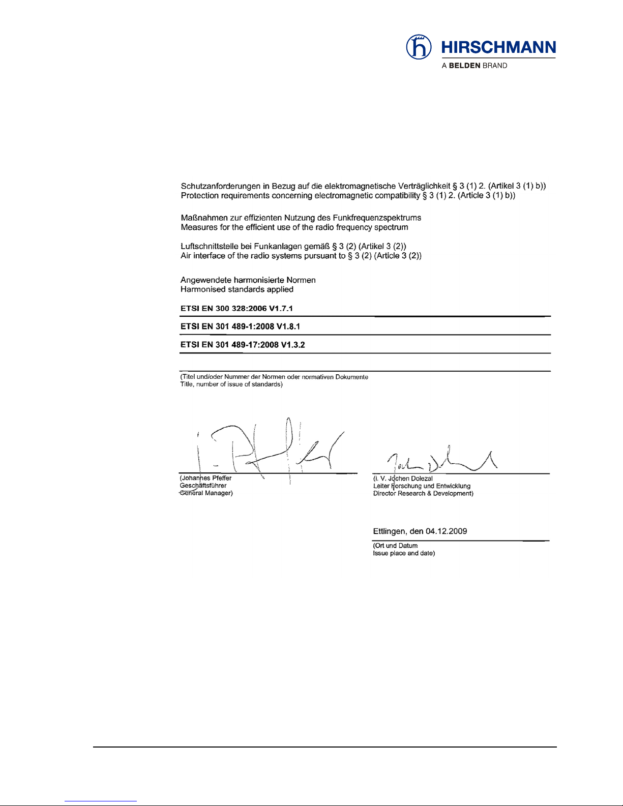
1.1 EU conformity declaration
© 2010 Hirschmann Automation and Control GmbH · Branch Office Ettlingen · E-mail: info.ecs@belden.com 7/29
21-810-19-0001_421826_en_Rev_B.doc / 2011-08-09 / Issue B / rk, kg.
Page 8
Safety instructions
© 2010 Hirschmann Automation and Control GmbH · Branch Office Ettlingen · E-mail: info.ecs@belden.com 8/29
21-810-19-0001_421826_en_Rev_B.doc / 2011-08-09 / Issue B / rk, kg.
Page 9
Product description
2 Product description
2.1 General
The iFLEX TRS 10 is a transceiver for the use of wireless sensors from the Hirschmann xSENSxxx-W1 family to a CAN bus.
Up to 4 wireless sensors can be connected wirelessly to a single iFLEX TRS 10. The number of
wireless sensors can be extended, as required, by using several transceivers.
How many sensors
can be connected?
All sensors from the xSENS-xxx-W1 family from Hirschmann’s extensive range of wireless sensors
can be used.
(the article numbers given on the right refer to the sensors including accessories)
Which wireless sen-
sors can be used?
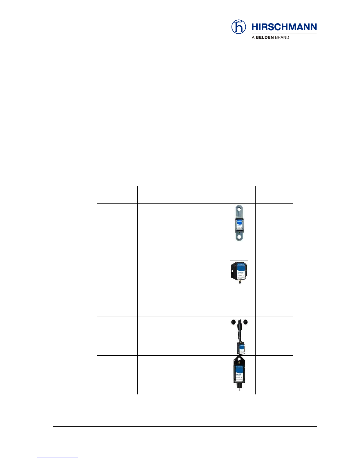
Application Product designation Article no.
(set)
Load measurement
fSENS KMD-006-W1 (up to 6 ton)
Art. no. 605792
alternatively also
fSENS KMD-020-W1 (up to 20 ton)
Art. no. 606345
Angle measurement
gSENS WGF-W1 (0 to 90°)
Art. no. 608016
e.g. for boom angle measurement
alternatively also
gSENS WGS-W1 (-15 to +15°)
Art. no. 608185
for inclination measurement
Wind measurement
iSENS WSS-W1
608179
Stroke end
monitoring
iSENS HES-W1
Art. no. 608015
608180
Table 1 Overview of xSENS-W1 wireless sensors
© 2010 Hirschmann Automation and Control GmbH · Branch Office Ettlingen · E-mail: info.ecs@belden.com 9/29
21-810-19-0001_421826_en_Rev_B.doc / 2011-08-09 / Issue B / rk, kg.
Page 10

Product description
2.2 Product features
The iFLEX TRS 10 has the following features:
Connects up to four wireless radio sensors with the CAN bus (expandable)
Simple setup of the wireless sensors via CAN bus
Automatic diagnostic function
CANopen slave in accordance with CiA DS-301/401
Transmission rate adjustable from 125 kbps to 1 Mbps
Battery monitoring for the connected wireless sensors
Protection class IP65, suitable for outdoor use
Operating temperature -40 to +85 °C
Voltage supply 10 to 30 V DC
2.3 Use for the intended purpose
The iFLEX TRS 10 is a transceiver used for the transmission of wireless sensor data to a CAN bus
using the CANopen protocol. Since impairment of the radio communication/range can occur, the
device must not be used in close proximity to antenna systems with a high HF transmission power
(e.g. radar / radio / TV / mobile telephone) or in close proximity to power supply systems.
2.4 Scope of supply
The scope of supply of the iFLEX TRS 10 with accessories (art. no. 608178)
consists of the following parts:
iFLEX TRS 10
Magnetic base antenna with 4 m connecting cable or short antenna
CAN T-piece M12
CAN connection cable, 0.6 m, with prefabricated plug connectors at both ends
User manual
© 2010 Hirschmann Automation and Control GmbH · Branch Office Ettlingen · E-mail: info.ecs@belden.com 10/29
21-810-19-0001_421826_en_Rev_B.doc / 2011-08-09 / Issue B / rk, kg.
Page 11

Product description
2.5 View of device
Operating
status
Indicators for
register
ed wireless sensors
channels 1 to 4
Indicator for
hoist limit
signal
Indicator for low
sensor battery
channels 1 to 4
Coaxial socket
for antenna
Central plug
Figure
1: View of the iFLEX TRS 10
© 2010 Hirschmann Automation and Control GmbH · Branch Office Ettlingen · E-mail: info.ecs@belden.com 11/29
21-810-19-0001_421826_en_Rev_B.doc / 2011-08-09 / Issue B / rk, kg.
Page 12

Product description
2.6 Dimensions
Figure 2: Dimensions of the iFLEX TRS 10 (with magnetic base antenna)
© 2010 Hirschmann Automation and Control GmbH · Branch Office Ettlingen · E-mail: info.ecs@belden.com 12/29
21-810-19-0001_421826_en_Rev_B.doc / 2011-08-09 / Issue B / rk, kg.
Page 13

Installation
3 Installation
3.1 Mounting the components
The iFLEX TRS 10 is supplied complete with all necessary mounting parts. Mounting can therefore
be performed simply and quickly. For mounting the wireless sensors, please refer to the instructions
provided with the respective sensor.
3.1.1 iFLEX TRS 10
The iFLEX TRS 10 must be mounted in a suitable place on a sufficiently firm surface with the connections at the bottom.
The distance between the holes in the housing is 102 mm.
3.1.2 Short Antenna
Antenna, 2.4 GHz
T
RS 10
Figure
3: Short, direct connection antenna
3.1.3 Magnetic base antenna
Antenna radiator 2.4 GHz
Antenna base
Magnetic baseplate
Figure 4: Magnetic base antenna (art. no.536023) with mounted radiator
Screw the antenna radiator hand tight
onto the thread on the TRS 10 or on the top side of the an-
tenna base until you feel a stop. (Remove the protective cap from the thread if necessary).
Preparation of the
antenna
© 2010 Hirschmann Automation and Control GmbH · Branch Office Ettlingen · E-mail: info.ecs@belden.com 13/29
21-810-19-0001_421826_en_Rev_B.doc / 2011-08-09 / Issue B / rk, kg.
Page 14

Installation
If applicable, the antenna has a magnetic base plate and adheres securely to all ferromagnetic
surfaces.
How do I mount the
antenna?
NOTE
Optimal ranges are achieved if the antenna is aligned in accordance with the alignment of
the wireless sensor antennas and can radiate as freely as possible.
Niches or recesses are therefore less suitable as mounting locations!
Please follow the instructions below for laying the antenna cable (if applicable):
How should the
cable be laid?
IMPORTANT
The antenna cable can be damaged if it is squeezed or kinked.
Therefore, lay the antenna cable in such a way that it is neither squeezed nor laid around
sharp edges!
IMPORTANT
The function of the antenna and hence the whole system can be impaired if a mismatching
antenna radiator is used.
Always use the antenna radiator contained in the scope of supply!
After laying the cable, connect the coaxial connector of the antenna to the antenna socket on the
underside of the iFLEX TRS 10 or connect the antenna directly to the base of the TRS 10. Screw
the connector on hand tight.
Where is the
antenna
connected?
3.2 Electrical connection
Connection of the device to an existing CAN bus is simple thanks to the fully prefabricated connecting cable (length 0.6 m) included in the scope of supply. The CAN T-piece included in the scope of
supply can also be used for this if necessary.
© 2010 Hirschmann Automation and Control GmbH · Branch Office Ettlingen · E-mail: info.ecs@belden.com 14/29
21-810-19-0001_421826_en_Rev_B.doc / 2011-08-09 / Issue B / rk, kg.
Page 15

Installation
© 2010 Hirschmann Automation and Control GmbH · Branch Office Ettlingen · E-mail: info.ecs@belden.com 15/29
21-810-19-0001_421826_en_Rev_B.doc / 2011-08-09 / Issue B / rk, kg.
CAUTION
Danger of electrical short-circuits.
Switch off all systems before commencing with the installation work!
IMPORTANT
Damage to the device if connected to an unsuitable power supply.
The device may only be connected to a DC voltage source of 10 V to 30 V!
3.2.1 Wiring of the central connector
Please refer to the following illustration for the pin configuration of the connector on the underside
of the iFLEX TRS 10:
Pin 1 +VDC (10 …30 V)
Pin 2 GND
Pin 11 CAN L
Pin 12 CAN H
Figure 5: Pin configuration of the central connector
3.2.2 Wiring of the connecting cable
Please refer to the following illustration for the wiring of the connecting cable (article no. 536025):
Figure 6: Wiring of the CAN connecting cable
Length:
0,6 m
Page 16

Commissioning
© 2010 Hirschmann Automation and Control GmbH · Branch Office Ettlingen · E-mail: info.ecs@belden.com 16/29
21-810-19-0001_421826_en_Rev_B.doc / 2011-08-09 / Issue B / rk, kg.
4 Commissioning
At least one functional wireless sensor must be available in order to commission and operate the
A guide to commissioning the iFLEX TRS 10 and connecting the wireless sensors is provided be-
1. First, open the battery compartment of the wireless sensor after undoing the 4 screws and
Figure 7: Steps for Removing Batteries
2. Next, remove the cover of the TRS 10 by pushing in the two tabs located on each side of the
Figure 8: Steps for Removing TRS 10 Cover
system.
low.
4.1 Adding a Wireless Sensor
remove the b
atteries as shown in Figure 7.
casing, as pictured below in Figure 8.
Page 17

Commissioning
3. After Removing the outer cover, supply power to TRS 10 by either using your Deutsch connector wired to your 10 to 30 volt power supply or use a DC power supply to provide 10 to 30
volts to pin 1 and ground to pin 2 of the connector. Refer to Figure 5 for the pin layout of the
connector.
4. Verify power is being supplied to the TRS 10 by checking to see if the “Power” Led is lit as
seen in Figure 9.
Figure 9: “Power” LED as indicated by the red light
5. Next, push and hold the red button located in the upper, left-hand corner of the TRS 10
board (Figure 10). Continue holding the button down for approximately 5 seconds until the
green LED, which corresponds to position 1 of the “Sensor Online” row located on the cover,
begins to blink slowly.
Figure 10: Red push button on TRS 10 board
6. Replace the batteries in the wireless sensor that you are trying to connect, following
the correct polarity. First, you will see the yellow LED located on the bottom of the sensor
turn on and stay lit for approximately 3 to 5 seconds. After the yellow LED on the sensor
changes to a short blink every 5 seconds, verify that the green LED in the “Sensor Online”
row, position 1 is now consistently lit and no longer flashing. If this is true, then your wireless
sensor has successfully connected to the TRS 10.
© 2010 Hirschmann Automation and Control GmbH · Branch Office Ettlingen · E-mail: info.ecs@belden.com 17/29
21-810-19-0001_421826_en_Rev_B.doc / 2011-08-09 / Issue B / rk, kg.
Page 18

Commissioning
7. To connect another wireless sensor, move to the next unoccupied position that corresponds
to the “Sensor Online” row located on the cover of the TRS 10, by holding down the same
red button previously used step 5. Follow steps 4 to 6 as a guide if needed.
8. When all of your sensors have been connected to the TRS 10, replace each cover of the
wireless sensors my tightening the four screws. As well, reattach the cover of the TRS 10
making sure the two clips that were pushed in during the removal process have now
snapped back into place. It is critical that all screws be properly tightened and the TRS 10
cover be fitted back to its original position in order to maintain weather resistant capabilities.
Note: If a sensor does not successfully connect, remove its batteries, wait 15 seconds and then
follow steps 4 through 6.
© 2010 Hirschmann Automation and Control GmbH · Branch Office Ettlingen · E-mail: info.ecs@belden.com 18/29
21-810-19-0001_421826_en_Rev_B.doc / 2011-08-09 / Issue B / rk, kg.
Page 19

Commissioning
4.2 Status LEDs
There are 10 LEDs on the front panel of the device, which indicate the status of various operating
conditions.
The meaning of the signals can be taken from the table:
LED: off
lights
flashes slowly flashes rapidly
No supply
voltage pre-
sent
Supply voltage is
present
Sensor reports an
alarm (e.g. hoist limit
switch) or link to the
indicated sensor is
lost
During the sys-
tem diagnosis
No sensor
registered to
this channel
Sensor registered to
this channel and
ready for operation
Radio link to the
sensor on this
channel inter-
rupted
Batteries of the wire-
less sensor on this
channel are almost
exhausted! (Capacity
less than 6.5%)
Replace the batter-
ies soon!
Table 2 Overview of status LED
© 2010 Hirschmann Automation and Control GmbH · Branch Office Ettlingen · E-mail: info.ecs@belden.com 19/29
21-810-19-0001_421826_en_Rev_B.doc / 2011-08-09 / Issue B / rk, kg.
Page 20

Commissioning
4.3 Troubleshooting
After wiring the iFLEX TRS 10, the device switches itself on as soon as a supply voltage is present
on the CAN bus. After switching on, the system begins with a self-diagnostic routine.
How is the device
switched on?
The self-diagnosis takes approx. 5 seconds. During these tests the LEDs light up successively with
a test pattern:
How long does the
self-diagnosis take?
LED key: off:
lights: flashes slowly: flashes rapidly:
If no wireless sensors have been registered and saved yet, only the ‘Power’ LED should be lit after
completion of the self-diagnosis:
How can I tell
whether the device is
working correctly?
If wireless sensors have already been registered and saved, the ‘Sensor Online’ LED of the corresponding channel lights up, indicating that the radio link has been established.
If a ‘Low Battery’ LED lights up, this means that the battery set in the respective wireless sensor is
exhausted (remaining capacity < 6.5%) and must be replaced as soon as possible.
What does it mean
when a ‘Low Battery’
LED lights up?
If a ‘Sensor Online’ LED flashes rapidly after conclusion of the self-diagnosis, this means that the
radio link to the sensor on the indicated channel has been interrupted.
What does it mean
when a ‘Sensor
Online’ LED flashes
rapidly?
NOTE
If the link to a wireless sensor is interrupted, rectify the fault first before putting the system
into operation.
© 2010 Hirschmann Automation and Control GmbH · Branch Office Ettlingen · E-mail: info.ecs@belden.com 20/29
21-810-19-0001_421826_en_Rev_B.doc / 2011-08-09 / Issue B / rk, kg.
Page 21

Service and maintenance
5 Service and maintenance
The iFLEX TRS 10 contains no serviceable parts and may therefore not be opened. The fuse inside the device is self-resetting and therefore does not need to be exchanged. If you notice malfunctions or differences between actual and displayed measured values, you should switch the
device off and have it checked and, if necessary, repaired immediately by an authorised Hirschmann service partner.
Clean the surface of the equipment occasionally with a damp cloth using a mild cleaning agent.
However, you should never use abrasive or alcohol-based cleaning agents, as these can damage
the housing or the front foil! The device must not be treated with a high pressure cleaner or similarly
aggressive methods under any circumstances!
IMPORTANT
Damage to the device due to the penetration of water and dirt.
Never clean the device with a high pressure cleaner!
Have damage to the decorative foil repaired professionally without delay!
Keep the contact area of the device plug and the antenna connector clean and occasionally check
that the connections are tight.
Occasionally check the connecting cable and antenna cable as well as the antenna itself. If parts
are damaged, these must be repaired properly or replaced immediately.
© 2010 Hirschmann Automation and Control GmbH · Branch Office Ettlingen · E-mail: info.ecs@belden.com 21/29
21-810-19-0001_421826_en_Rev_B.doc / 2011-08-09 / Issue B / rk, kg.
Page 22

Technical data
6 Technical data
Article designation iFLEX TRS 10
Article number 608178 (complete with accessories, see scope of supply)
Operating voltage 10 - 30 V DC
Fuse Self-resetting internal fuse, 500 mA
Transmission frequency 2.45 GHz, ISM band, registration/licence-free
IEEE 802.15.4 standard, DSSS /OQPSK modulated
Class 1 radio system in accordance with FTEG and 1999/5/EU
(R&TTE)
Antenna 2.4 GHz, with magnetic base and screwed on antenna radiator,
4m connecting cable, RP-SMA plug
Range approx. 300 m (depending upon environmental conditions)
CAN interface ISO 11898, high-speed CAN, standard identifier (11-bit)
CAN protocol CANopen slave CiA DS-301/DS401
Data rate 125 kbit/s (standard), 250 kbit/s, 500 kbit/s, 750 kbit/s, 1 Mbit/s
Node ID Standard: 31
dec
/ 1F
hex
(configurable)
CE conformity ETSI EN 300 328
ETSI EN 301 489-1
ETSI EN 300 489-17
EN 60950-1
FCC conformity FCC 47 CFR Part 15, Radio Frequency Devices, Subpart B
Control elements none
Displays 10 status LEDs
for signalling various operating conditions
Electrical connection Central connector (German) 12-pole (on underside of device)
Antenna connection RP-SMA, coaxial (on the underside of the device)
Dimensions H 134 mm x W 118,2 mm x D 36,3 mm
Weight 0.262 kg (device only)
Distance between
mounting holes 102,1 mm
Operating temperature range -40 ºC to +85 ºC
Storage temperature range -50 ºC to +85 ºC
Protection class IP 65
Scope of supply iFLEX TRS 10 with accessories:
- Magnetic base antenna with 4 m connecting cable
- Antenna radiator 2.4 GHz
- Connecting cable, 0.6 m, fully prefabricated
- T-piece for CAN bus
- User manual
© 2010 Hirschmann Automation and Control GmbH · Branch Office Ettlingen · E-mail: info.ecs@belden.com 22/29
21-810-19-0001_421826_en_Rev_B.doc / 2011-08-09 / Issue B / rk, kg.
Page 23

Appendix
7 Appendix
7.1 Object listing table
Index Sub Index Default Value Comment
0x1000
0x00
RO4
Part Number
0x1001
0x00
RO1
0 Error Register
0x1002
0x00
RO4
0 Status Register
0x1008
0x00
RO4
Text for part type
0x1009
0x00
RO4
BOM revision
0x100A
0x00
RO4
Software Revision
0x00
RO1
1 Number of sub-indexes
0x1010
0x01
RW4
3 CAN save object – write “save” here to save changes
made via CAN bus to EEPROM
0x1017
0x00
RW2
0x01F4 Heartbeat time in ms.
Setting to 0 will disable the heartbeat
0x00
RO1
4 Number of sub-indexes
0x01
RO4
0x0000008F Vendor ID
0x02
RO4
0xF0000001 Module Type
0x03
RO4
0x00000001 Revision Number
0x1018
0x04
RO4
0x00000001 Serial Number (changes for each unit)
0x00
RO1
2 Number of sub-indexes
0x01
RO2
0x600+NodeID CAN ID to receive SDO messages (61F h)
0x1200
0x02
RO2
0x580+NodeID CAN ID to transmit SDO messages (59F h)
0x00
RO1
5 PDO1 (transmit)
0x01
RO2
0x180+NodeID COB-ID used by PDO1 (19F h)
0x02
RO1
0x03 transmission type
0x1800
0x05
RO2
500 event timer
0x00
RO1
5 PDO2 (transmit)
0x01
RO2
0x280+NodeID COB-ID used by PDO2 (29F h)
0x02
RO1
0x03 transmission type
0x1801
0x05
RO2
200 event timer
0x00
RO1
5 PDO3 (transmit)
0x01
RO2
0x380+NodeID COB-ID used by PDO3 (39F h)
0x02
RO1
0x03 transmission type
0x1802
0x05
RO2
200 event timer
0x00
RO4
3 Number of channels in 1st TPDO
0x01
RO4
0x6100 01 10 1st object = 1st 16 bit digital input (A2B)
0x02
RO4
0x6100 02 10 2nd object = 2nd 16 bit digital input = f(Hz)
0x1A00
0x03
RO4
0x6100 03 10 3rd object = 3rd 16 bit digital input = T(ms)
0x00
RO1
4 Number of channels in 2ND TPDO
0x01
RO4
0x6401 01 10 1st object = 1st analog input, 16 bit resolution
0x02
RO4
0x6401 02 10 2nd object = 2nd analog input, 16 bit resolution
0x03
RO4
0x6401 03 10 3rd object = 3rd analog input, 16 bit resolution
0x1A01
0x04
RO4
0x6401 04 10 4th object = 4th analog input, 16 bit resolution
© 2010 Hirschmann Automation and Control GmbH · Branch Office Ettlingen · E-mail: info.ecs@belden.com 23/29
21-810-19-0001_421826_en_Rev_B.doc / 2011-08-09 / Issue B / rk, kg.
Page 24

Appendix
© 2010 Hirschmann Automation and Control GmbH · Branch Office Ettlingen · E-mail: info.ecs@belden.com 24/29
21-810-19-0001_421826_en_Rev_B.doc / 2011-08-09 / Issue B / rk, kg.
Index Sub Index Default Value Comment
0x00
RO1
4 Number of channels in 3RD TPDO
0x01
RO4
0x2A00 01 08 1st object = 1st battery level & type, 8 bit resolution
0x02
RO4
0x2A00 02 08 2nd object =2nd battery level & type,8 bit resolution
0x03
RO4
0x2A00 03 08 3rd object =3rd battery level & type, 8 bit resolution
0x1A02
0x04
RO4
0x2A00 04 08 4th object =4th battery level & type, 8 bit resolution
0x2000
0x00
RO4
0x12345678 Serial number lo
0x2001
0x00
RO4
0x13572468 Serial number hi
0x2007
0x00
RW1
0x1F Node ID, 1 – 127 allowed (default 1F h)
0x2008
0x00
RW1
0x04 4=125 kbit/s (default)
5=250 kbit/s 6=500 kbit/s 7=800 kbit/s 8=1Mbit/s
0x00
RO1
0x04 Number of battery levels
0x01
RO1
0x00 Battery level for channel 1 0x0 to 0xF 0x00 = 6.5%
Replace Batteries 0x01 = 13.0% … 0x0F = New Battery
in sensor (2 minutes only)
0x02
RO1
0x00 Battery level for channel 2
0x03
RO1
0x00 Battery level for channel 3
0x2A00
0x04
RO1
0x00 Battery level for channel 4
0x2A01
0x00
RW1
0x00 Installation Menu Status
0x00
RO1
0x04 Number of possible sensors
0x01
RW2
0xFF Sensor ID for channel 1 (0x0000 - 0xFFFE)
0x02
RW2
0xFF Sensor ID for channel 2
0x03
RW2
0xFF Sensor ID for channel 3
0x2A02
0x04
RW2
0xFF Sensor ID for channel 4
0x00
RO1
0x04 Number of possible sensors
0x01
RW1
0xFF Sensor type for channel 1
0x00 = Loadcell fSENS KMD-xxx-W1
0x20 = (Linerider)
0x60 = Windspeed Sensor iSENS WSS-W1
0x40 = Angle Sensor gSENS WGF/WGS-W1
0x80 = A2B switch iSENS HES-W1
0xFF = No sensor installed
0x02
RW1
0xFF Sensor type for channel 2
0x03
RW1
0xFF Sensor type for channel 3
0x2A03
0x04
RW1
0xFF Sensor type for channel 4
0x00
RO1
0x03 Number of sub-indexes
0x01
RO2
0x0004 A2B Status: LSByte contains bitwise data 0x00F2 =
A2B OK 0x0004 = Alarm (switch tripped, comm. lost)
0x02
RO2
0x0000 Anemometer frequency in Hz – Higher = Faster
Not Implemented
0x6100
0x03
RO2
0xFFFF Anemometer period in ms – Higher = Slower
Not Implemented
0x00
RO1
4 Number of analog inputs
0x01
RO2
Analog value 1st analog channel
0x02
RO2
Analog value 2nd analog channel
0x03
RO2
Analog value 3rd analog channel
0x6401
0x04
RO2
Analog value 4th analog channel
Page 25

Appendix
7.2 Wiring of the adaptor cable for PCAN-USB
The wiring of the adaptor cable from the CAN connecting cable to the PCAN-USB plug can be
taken from the diagram below:
Length:
0,5 m
Figure 11: Wiring of the adaptor cable for PCAN-USB
7.3 List of tables and illustrations
Table 1 Overview of xSENS-W1 wireless sensors................................................ 9
Table 2 Overview of status LED ..........................................................................19
Figure 1: View of the iFLEX TRS 10.................................................................... 11
Figure 2: Dimensions of the iFLEX TRS 10 (with magnetic base antenna) ........12
Figure 3: Short, direct connection antenna.......................................................... 13
Figure 4: Magnetic base antenna (art. no.536023) with mounted radiator.......... 13
Figure 5: Pin configuration of the central connector ............................................ 15
Figure 6: Wiring of the CAN connecting cable..................................................... 15
Figure 7: Steps for Removing Batteries............................................................... 16
Figure 8: Steps for Removing TRS 10 Cover ...................................................... 16
Figure 9: “Power” LED as indicated by the red light ............................................17
Figure 10: Red push button on TRS 10 board..................................................... 17
Figure 11: Wiring of the adaptor cable for PCAN-USB........................................ 25
© 2010 Hirschmann Automation and Control GmbH · Branch Office Ettlingen · E-mail: info.ecs@belden.com 25/29
21-810-19-0001_421826_en_Rev_B.doc / 2011-08-09 / Issue B / rk, kg.
Page 26

Appendix
© 2010 Hirschmann Automation and Control GmbH · Branch Office Ettlingen · E-mail: info.ecs@belden.com 26/29
21-810-19-0001_421826_en_Rev_B.doc / 2011-08-09 / Issue B / rk, kg.
Page 27

Feedback
Feedback
What is your opinion about this manual? We always try to describe the products fully in our manuals, as well as providing important background knowledge to ensure trouble-free operation.
We take the task of continuous improvement and reduction of errors very seriously. Your comments
and suggestions help us to increase the quality and level of information for this document.
Your assessment of this manual:
excellent good satisfactory so-so poor
Accuracy O O O O O
Readability O O O O O
Ccomprehensibility O O O O O
Examples O O O O O
Structure / Layout O O O O O
Completeness O O O O O
Illustrations / Images O O O O O
Drawings, Diagrams O O O O O
Tables O O O O O
Did you discover errors in this manual?
If so, in which section number or which part of the manual?
© 2010 Hirschmann Automation and Control GmbH · Branch Office Ettlingen · E-mail: info.ecs@belden.com 27/29
21-810-19-0001_421826_en_Rev_B.doc / 2011-08-09 / Issue B / rk, kg.
Page 28

Feedback
© 2010 Hirschmann Automation and Control GmbH · Branch Office Ettlingen · E-mail: info.ecs@belden.com 28/29
Suggestions for improvement and additional information:
General comments:
Sender:
Company / Department
Name / Phone
Street
Zip code / City
Date / Signature
Dear user,
please complete and return both pages of this feedback:
via fax to: +49 (0)7243 709 3222
via mail to: Hirschmann Automation and Control GmbH
Documentation
Hertzstr. 32-34
76275 Ettlingen / Germany
Thank you !
21-810-19-0001_421826_en_Rev_B.doc / 2011-08-09 / Issue B / rk, kg.
Page 29

Notes
© 2010 Hirschmann Automation and Control GmbH · Branch Office Ettlingen · E-mail: info.ecs@belden.com 29/29
21-810-19-0001_421826_en_Rev_B.doc / 2011-08-09 / Issue B / rk, kg.
 Loading...