

Page 1
1
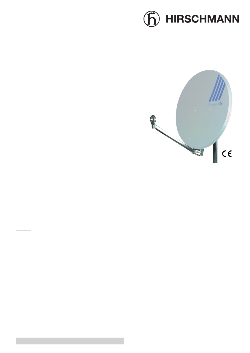
Beschreibung
•
Zum festen Ausrichten auf einen Satelliten im
Frequenzbereich 10,7 - 12,75 GHz
•
Aluminium-Reflektor
•
Einstellskala für Elevation
•
Stabile Halterung
•
Korossionsgeschützte Teile
•
Kabelführung in Feedarm und Rückenteil
•
Feedarm vormontiert, ausklappbar
•
Feedhalter für alle Empfangssysteme des HitFesat und HiQ-Sortiments
•
Rückenteil und Masthalter vormontiert,
zusammengeklappt - für einfache Montage, keine
Einzelteile
Kombinierbar mit
•
allen Empfangssystemen CS...
•
Wandhalter WH..., MHR...
•
Standgestell STG 60
D
045 882-001-07-1207
Deutsch: Seite 1 English: page 5
Betriebsanleitung
Offset-Parabolantennen
Hit FESAT 65
Hit FESAT 75
Hit FESAT 85
Page 2

2
Montage
Die Parabolantenne ist bereits vormontiert und
besteht aus nur noch zwei Teilen:
– dem kompletten Rückenteil mit Masthalterung und
ausklappbarem Feedarm und
– dem Reflektor.
Beachten Sie bei der Montage die Erdungsund Sicherheitsvorschriften nach EN 50 083,
Teil 1!
Montage des Rückenteils am Mast
•
Nehmen Sie das
Rückenteil aus der
Verpackung und
klappen Sie den
Masthalter aus.
•
Montieren Sie
das Rückenteil an
einem Antennenmast, Standfuß
oder einem Wandhalter.
Der Antennenmast, der Standfuß
oder der Wandhalter soll der
Antennengröße in
der Stabilität
angepaßt und
senkrecht
vormontiert sein.
•
Die Transportsicherung am
Feedarm entfernen,
den Feedarm ausklappen und mit
der Innensechskantschraube
unten am Rückenteil festschrauben.
•
Das Rückenteil nach der
Elevationsskala
einstellen und
provisorisch mit
der Flügelmutter
festschrauben.
Die endgültige
Befestigung erfolgt
nachdem die
Parabolantenne
ausgerichtet
wurde.
Montage des Empangssystems
•
Das Empfangssystem am Feedhalter montieren.
Hierbei den Haltebügel des Feedhalters beim Lösen
der Schrauben
nach unten halten,
damit sich der
Plastikring, der die
Schraube sichert,
etwas nach unten
bewegt
(andernfalls kann
die Schraube bei erneutem Anziehen schräg zum
Gewinde stehen).
Die Kabel im Feedarm und im Rückenteil verlegen. Die Kabelenden in der Länge anpassen, FStecker montieren und anschließen.
Montage des Reflektors
•
Den Parabolreflektor mit den
Aussparungen
über die vier
Innensechskantschrauben am
Rückenteil schieben und festschrauben.
Den Reflektor
nach dem Einsetzen und noch
während der Befestigung nach
unten auf Anschlag ziehen.
•
Erforderliche Anziehkraft der Reflektorschrauben:
7-8 Nm.
Page 3
3
Technische Daten
Typ Hit FESAT 65 Hit FESAT 75 Hit FESAT 85
Bestellnummer lichtgrau 965 038-001 965 039-001 965 040-001
schiefergrau 965 038-011 965 039-011 965 040-011
ziegelrot 965 038-023 965 039-023 965 040-023
Reflektor-Ø m 0,65 0,75 0,85
Frequenzbereich GHz 10,7 - 12,75 10,7 - 12,75 10,7 - 12,75
Gewinn bei 10,95 GHz, min. dBi 36 37,3 38,3
Halbwertsbreite 2,85° 2,4° 2,1°
Offsetwinkel 21,3° 21° 21,1°
Rauschtemperatur K 46 42 40
(bei 30° Elevation)
Feedaufnahme mm 40 * 40 * 40 *
Halterung für Standrohr-Ø mm 40 - 89 40 - 89 40 - 89
Einstellbereich Elevation 15° - 45° 15° - 45° 15° - 45°
Azimut 0° - 360° 0° - 360° 0° - 360°
Windlast N 375 480 600
(bei 800 N/m2Staudruck)
Breite x Höhe cm 67 x 71,5 75 x 80 85,5 x 90,5
Gewicht kg 6 6,5 9
Verpackungsmaß cm 84 x 69 x 13 78 x 94 x 14 105 x 89 x 14
Lieferumfang - Reflektor mit Rückteil
- Tragarm mit Alu-Feedhalter (Österreich: Kunststoff)
- El/Az-Masthalterung
* Auslieferung in Österreich mit Kunststoffhalter 23/40 mm
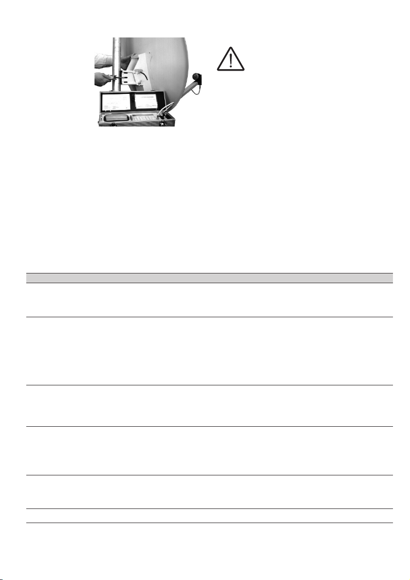
Parabolantenne ausrichten
•
Die
Antennenableitung an ein
Satellitenpegelmessgerät (z.B.
UPM ....)
anschließen.
Die Parabolantenne durch
Schwenken am
Mast in
horizontaler
Richtung und durch Verändern der Elevation in
vertikaler Richtung auf optimalen Empfang
einstellen.
•
Nach dem Ausrichten des Parabolreflektors die
Flügelmuttern der Masthalterung und die
Flügelmutter zum Einstellen der Elevation am
Rückenteil festziehen.
Kontrolle aller Schrauben und
Muttern
•
Zum Schluss alle Flügelmuttern und
Schrauben, auch die der bereits
vormontierten Teile, auf festen Sitz
kontrollieren und gegebenenfalls
festziehen.
•
Empfehlung zur Langzeitsicherheit: 1 x jährlich den
korrekten Sitz aller Schrauben überprüfen und ggf.
nachziehen.
Page 4

4
Zubehör
•
NTS - 1 Set, Best. - Nr. 940304001
Multifeed-Nachrüstset für ältere Hit Fesat Anlagen mit Kunststoff LNB Halter (je 1x Schnittstellenstück, Alu
- Feedhalter u. Werkzeug)
•
MFU - 1 Set, Best. - Nr. 940305001
Multifeed-Upgrade-Set zum Empfang von 2 Satelliten mit Abstand 6°/min. ca. 4,5° (je 1x 17 cm AluMultifeedschiene, 40 mm Alu - Feedhalter)
•
MFS - 3/4 Alu, Best. - Nr. 940306001
34 cm Alu-Multifeed-Schiene zur Aufnahme von bis zu 4 LNB - Haltern
•
FH - 40 Alu, Best. - Nr. 940308001
Alu-Feedhalter 40 mm zur Aufnahme von Universal-Empfangssystemen
•
FH - 23 Alu, Best. - Nr. 940307001
Alu-Feedhalter 23 mm zur Aufnahme von Universal-Empfangssystemen
Zubehör für Österreich:
•
MFSK 2 SET, Best. - Nr. 981001-165
Multifeed Schiene 2-fach, Alu für Satellitenabstände zwischen 4,5° bis 6° (je 1 x Schnittstellenstück, Alu 1
Stk. Alu Schiene (kurz, 17 cm), 2 Stk. Alu-LNB-Halter 40 mm, + Inbusschlüssel u. Schrauben)
•
MFSL 3 SET, Best. - Nr. 981001-166
Multifeed Schiene 3-fach, Alu für Satellitenabstände zwischen 4,5° bis 13° (je 1 x Schnittstellenstück, Alu 1
Stk. Alu Schiene (lang, 38 cm), 3 Stk. Alu-LNB-Halter 40 mm, + Inbusschlüssel u. Schrauben)
•
Hit DFH 852, Best. - Nr. 965069-001
Doppelfeedhalter zum Empfang von zwei Satelliten mit 6° Abstand
Triax-Hirschmann Austria GmbH
Oberer Paspelsweg 6 – 8
A-6830 Rankweil-Brederis
Tel. +49 (0) 55 22 / 307-0
Triax-Hirschmann Multimedia GmbH
Karl-Benz-Str. 10
D-72124 Pliezhausen
Tel. +49 (0) 180 32 32-341
www.triax-hirschmann.com
Page 5

5
Description
•
For fixed alignment with a satellite in the
frequency range 10.7 - 12.75 GHz
•
Aluminium reflector
•
Adjustment scale for elevation
•
Strong mount
•
Parts protected from corrosion
•
Cable channel in the feed arm and spine section
•
Feed arm pre-assembled, folds out
•
Feed mount for all receiving systems of the Hit
FESAT and the HiQ series
•
Spine section and mast fixing bracket
preassembled, folded together - for simple
installation, no loose parts
Can be combined with
•
all CS... receiving systems
•
WH..., MHR... wall brackets
•
STG 60 mount
English
Operating instructions
Offset Parabolic Antennas
Hit FESAT 65
Hit FESAT 75
Hit FESAT 85
GB
Page 6

6
Installation
The parabolic antenna is already pre-assembled and
comprises only two parts:
– the complete spine section with mast fixing
bracket and feed arm that folds out, and
– the reflector.
When installing, observe the earthing and
safety regulations in EN 50 083, Part 1
Fitting the spine section to the mast
•
Take the spine
section out of
the packaging
and fold out the
mast fixing
bracket.
•
Fit the spine
section to an
antenna mast,
free-standing
mount or wall
bracket. The
antenna mast,
free-standing
mount or wall
bracket must be of
a size appropriate
for the size of the
antenna, and be
vertical.
•
Remove
the transport clip on
the feed arm, fold
out the feed arm
and fix in position
by tightening the
hexagon socket
head bolt at the
base of the spine
section.
•
Adjust the
spine section
using the elevation
scale and tighten
provisionally using
the wing nuts.
Final tightening is
performed after
the parabolic
antenna has been
aligned.
Fitting the receiving system
•
Fit the receiving
system to the feed
bracket. Keep the
mounting bracket
down while unscrewing - then
the plastic ring
moves down a
little (otherwise the
screw may cant to
the winding in
case of refixing).
Lay the cable in
the feed arm and
spine section. Adjust the length of the cable, fit
an F-type plug and connect.
Fitting the reflector
•
Slide on the reflector with the recesses over the four
hexagon socket
head bolts towards
the spine section
and bolt in place.
Pull the reflector
after assembling
and during the
fixing downwards
onto stop position.
•
Tighten the
reflector screws
with 7-8 Nm.
Page 7

7
Aligning the parabolic antenna
•
Connect
the antenna
feed to a
satellite signal
strength meter
(e.g. UPM ....).
Adjust the
parabolic
antenna for
optimal
reception by
swivelling in the
horizontal direction around the mast and by
changing the elevation in the vertical direction.
•
Tighten the wing nuts on the mast fixing bracket
and on the spine section for adjusting the
elevation.
Check all bolts and nuts
•
Finally check all wing nuts and bolts,
also on the pre-assembled parts, for
tightness, retighten if necessary.
•
Recommendation for long-term safety: please
check once per year all screws, retighten if
necessary.
Technical data
Type Hit FESAT 65 Hit FESAT 75 Hit FESAT 85
Order Number light grey 965 038-001 965 039-001 965 040-001
slate grey 965 038-011 965 039-011 965 040-011
brick red 965 038-023 965 039-023 965 040-023
Reflector Ø m 0.65 0.75 0.85
Frequency Range GHz 10.7 - 12.75 10.7 - 12.75 10.7 - 12.75
Gain at 10.95 GHz, min. dBi 36 37.3 38.3
3 dB Width 2.85° 2.4° 2.1°
Offset Angle 21.3° 21° 21.1°
Noise Temperature K 46 42 40
(at 30º elevation)
Feed Mount mm 40 * 40* 40*
Bracket for Mast Ø mm 40 - 89 40 - 89 40 - 89
Adjustment Range Elevation 15° - 45° 15° - 45° 15° - 45°
Azimuth 0° - 360° 0° - 360° 0° - 360°
Wind Load N 375 480 600
(at 800 N/m2suction pressure)
Width x Height cm 67 x 71.5 75 x 80 85.5 x 90.5
Weight kg 6 6.5 9
Packaging Dimensions cm 84 x 69 x 13 78 x 94 x 14 105 x 89 x 14
Items Supplied - Reflector with Spine Section
- Carrying Arm with Feed Holder Alu /
- El/Az Mast Fixing Bracket
* Delivery in Austria: with Feed holder 23/40 mm
Page 8

Triax-Hirschmann Austria GmbH
Oberer Paspelsweg 6 – 8
A-6830 Rankweil-Brederis
Phone +49 (0) 55 22 / 307-0
Triax-Hirschmann Multimedia GmbH
Karl-Benz-Str. 10
D-72124 Pliezhausen
Phone +49 (0) 180 32 32-341
www.triax-hirschmann.com
Accessories
•
NTS - 1 Set, Ord.-No. 940304001
Multifeed upgrade set for existing Hit Fesat systems with plastic feedholder (interface piece, diecast Alu
feed mount 40 mm and tool kit )
•
MFU - 1 Set, Ord.-No. 940305001
Alu multifeed extension (short, 17 mm) and Alu feed mount 40 mm.
For receiving 2 satellites, distance 4,5°...6°.
•
MFS - 3/4 Alu, Ord.-No. 940306001
Alu multifeed extension (long, 38 mm) for the support of up to 4 LNB holders
•
FH - 40 Alu, Ord.-No. 940308001
Alu feedholder 40 mm for the support of one universal LNB
•
FH - 23 Alu, Ord.-No. 940307001
Alu feedholder 23 mm for the support of one universal LNB
Accessories, only for Austria:
•
MFSK 2 SET, Ord.-No. 981001-165
Multifeed set Alu, for receiving 2 satellites 4,5°...6° (interface piece, diecast Alu feed mount 40 mm, alu
extension 17 cm, 2 LNB holders 40 mm and tool kit
•
MFSL 3 SET, Ord.-No. 981001-166
Multifeed set Alu, for receiving 3 satellites 4,5°...13° (interface piece, diecast Alu feed mount 40 mm, alu
extension 38 cm, 3 LNB holders 40 mm and tool kit
•
Hit DFH 852, Ord.-No. 965069-001
Doublefeed holder, for receiving 2 satellites, distance 6°
 Loading...