

Page 1
Montageanleitung
Automatic-Antenne
Installation Instructions
Automatic antenna
Instruction de montage
Antenne automatique
HIT AUTA 5091
estell-Nr. / Ord. code / N° de cde.
B
921 008-001
HIT AUTA 5091 SW
estell-Nr. / Ord. code / N° de cde.
B
921 010-001
Die beschriebenen Leistungsmerkmale sind nur
dann verbindlich, wenn sie bei Vertragsabschluss ausdrücklich vereinbart wurden. Diese
Druckschrift
munication GmbH
den beschriebenen Antennen und Antennenzubehör (Kabel, Stecker etc.) geprüft. Dennoch
können Abweichungen hinsichtlich der Richtigkeit oder Genauigkeit nicht ausgeschlossen
werden, sodass Hirschmann für die vollständige Übereinstimmung keine Gewähr übernimmt. Hirschmann behält sich das Recht
vor, den Inhalt dieser Druckschrift ohne
Ankündigung zu ändern.
wurde von Hirschmann Car Com-
auf Übereinstimmung mit
The performance features described here
are binding only if they have been expressly
guaranteed in the contract. This publication
has been created by Hirschmann Car Communication GmbH according to the best of
our knowledge.
Hirschmann reserves the right to change
the contents of this manual without prior
notice.
Hirschmann can give no guarantee in respect of the correctness or accuracy of the
details in this publication.
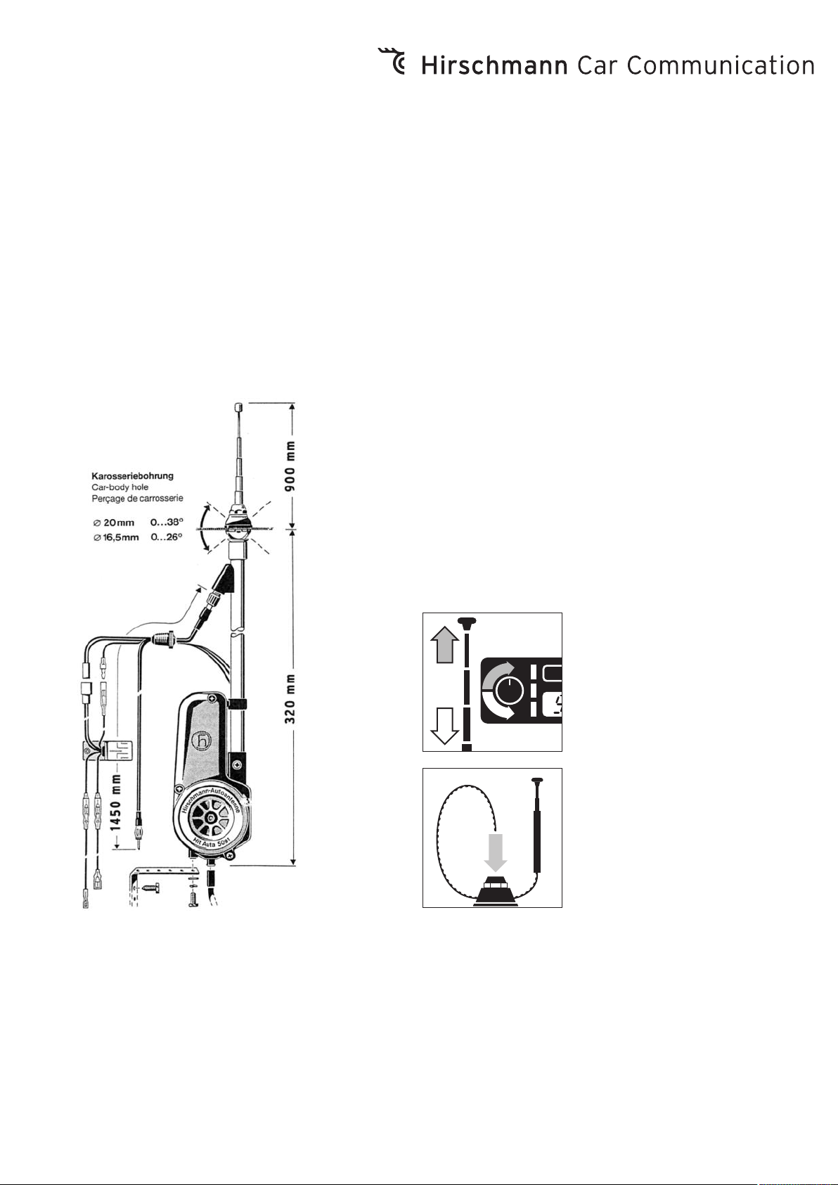
Radio einschalten – Antenne fährt aus
Radio ausschalten – Antenne fährt ein
Switch on radio – aerial will extend
Switch off radio – aerial will retract
Mettre en route la radio – l'antenne sort
Arrêter la radio – l'antenne rentre
Einfacher Teleskopwechsel ohne Ausbau der
Antenne möglich.
Easy telescope exchange possible without
aerial removable
Changement du télescope simple et possible
sans démonter l'antenne
La société Hirschmann Car Communication
GmbH ne se porte garante de la véracité des
informations techniques que si elles ont été
spécifiées de manière expresse à la signature
du contrat.
Le contenu de ce document a été minutieusement contrôlé afin de s’assurer qu’il corresponde bien aux antennes et accessoires
(câbles, connecteurs) décrits. Toutefois,
Hirschmann ne peut en aucun cas être tenu
responsable de l’exactitude de ces informations. Hirschmann se réserve le droit de
modifier sans préavis le contenu de ce document.
Page 2
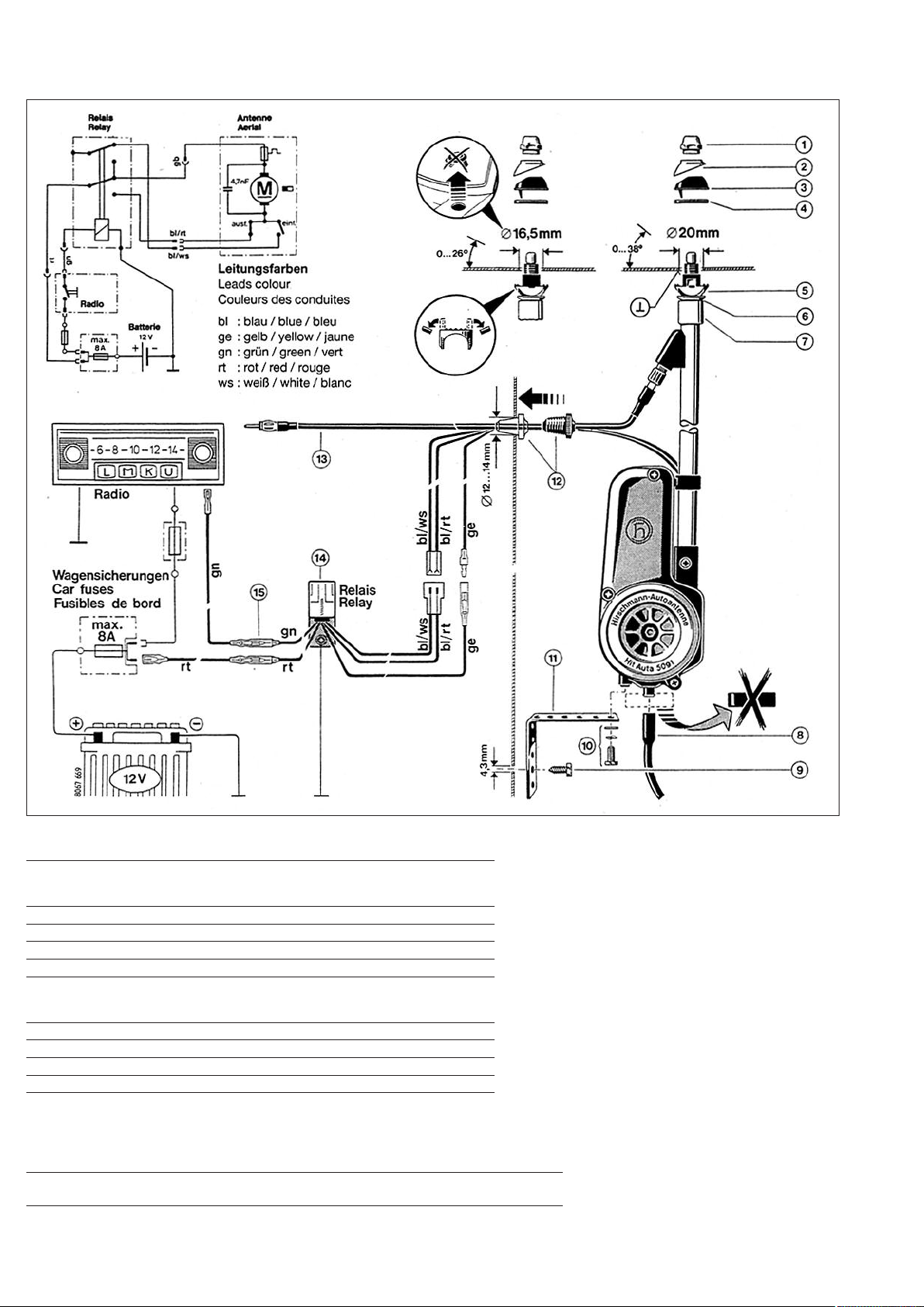
Schaltplan
Schematic diagram
Schéma de connexions
Einbauschema
Schematic for installation
Schéma de montage
Lieferumfang / Scope of delivery / Gamme de livraison
Pos. Bennenung
Nr. Type
No. Dénomination
1-6 Antennenkopf komplett / Antenna base compl. / Tête d'antenne complète
7 Distanzring / Spacer / L'anneau de distance
8 Schlauch / Drain tube / Tuyau
9 Blechschraube / Screw / Vis parker (B 6,3 x 16 DIN 7976)
10 Sechskantschraube / Screw / Vis à tête hexagonal (M 5 x 12 DIN 933)
11 Haltelasche / Bracket / Bride de fixation
12 Kabeltülle / Grommet / Passe-fil
13 Antennenkabel / Antenna cable / Câble d'antenne
14 Relais / Relay / Relais
Federring / Spring washer / Bague à ressort (B 5 DIN 127)
Scheibe / Lock washer / Disque (A 5,3 DIN 125)
Ersatzteleskope / Replacement masts / Télescope de rechange:
820 764-011 blank verchromt / chromium plated / chromée
821 362-011 schwarz verchromt / black chromium plated / chromée noire
2
Page 3

D GB F
Einbauanleitung
• Die Antenne kann in Wagen mit 12V Batte-
rie ( Minus an Masse ) im spritzwassergeschützten Bereich des Radkastens oder im
Kofferraum eingebaut werden.
• An der Einbaustelle ein Loch mit Ø 20 mm
einarbeiten. Die Neigung der Karosserie
kann dabei bis 38° betragen.
• Bei vorhandenen Bohrungen mit Ø 16,5 mm
kann der serienmäßige Antennenkopf verwendet werden. An der Wippe 5 müssen
dazu die beiden Stege abgebrochen werden.
Die Neigung der Karosserie kann dabei bis
ca. 26° betragen.
• Für den Einbau in schmale Kotflügel, bzw.
in stärker geneigte, können die auf der
Verpackung angezeigten zusätzlichen
Antennenköpfe verwendet werden, wobei
der Distanzring 7 teilweise entfällt.
• Das Karosserieblech auf der Unterseite
um die Bohrung herum blank machen und
mit Kontaktschutzfett bestreichen.
Dadurch wird eine gute Masseverbindung
für die Abschirmung und Schutz vor Korrosion erreicht.
• Von der Antenne die Teile 1, 2, 3 und 4
abnehmen. Die Transportscheibe entfernen und den Kunststoffschlauch 8 am
Antriebsgehäuse aufstecken.
• Das beiliegende Antennenkabel am Anten-
nenstutzen aufschrauben.
• Die Antenne von unten in die Karosserie
einsetzen. Die Wippe 5 in der Schale 6 auf
dem Distanzring 7 so drehen, dass sie
rund um die Bohrung anliegt.
• Die Halbkugel 3 mit der Dichtunterlage 4
von oben durch die Bohrung in der auf der
Unterseite anliegenden Wippe 5 einfügen.
• Die Halbschale 2 und die Mutter 1 aufset-
zen. Die Mutter leicht anziehen.
• Die Antenne ausfahren und das Teleskop
ausrichten. Zum Ausfahren das blau/rote
Motorkabel mit dem Plus-, das gelbe mit
dem Minuspol der 12 V Batterie verbinden.
Die Haltelasche 11 entsprechend biegen,
am Antriebsgehäuse festschrauben 10 und
mit der Blechschraube 9 an der inneren
Karosserie bzw. einer Verstrebung befestigen.
• Die Mutter 1 am Antennenkopf anziehen
(max. 4 Nm).
• Das Antennenkabel und die Motoran-
schlussleitungen verlegen. Karosseriedurchführung für Kabeltülle bohren (Ø 12-14
mm) und zur Abdichtung die Kabeltülle 12
einsetzen.
• Der elektrische Anschluss erfolgt über das
beigefügte Relais mit 2 Wechslern 14,
welches zwischen Antenne und Autoradio
an geschützter Stelle im Wageninnern,
befestigt wird. Dabei muss der Befestigungsbügel des Relais mit der Fahrzeugmasse elektrisch leitend verbunden werden.
• Die Leitungen entsprechend der Farb-
zeichnung zusammenstecken.
Bei Heckeinbau ist zusätzlich der
Verlängerungskabelsatz HIT AUKAB 420,
Bestell-Nr. 820 640-001 (4 m lang) erforderlich. Dabei werden die elektrischen
Anschlussleitungen bei 15 getrennt und die
Verlängerungsleitungen dazwischen
gesteckt.
Den längeren Schlauch zur sicheren Wasserableitung aus dem Kofferraum durch den
Wagenboden verwenden.
Installation instructions
• The antenna can be installed in cars with a
12V battery (minus connected to ground)
in an area of the wheel housing which is
protected against splash water or in the
trunk.
• Drill a 20 mm (13/16") dia. hole in the car
body at the installation point. At that spot
the inclination of the car body must not
exceed 38°.
• For existing holes of 16.5 mm dia. the
stan-dard aerial base can be used. Previously the two bars at the lower spherical
half 5 should be broken off. In this case
the car body inclination can be about 26°.
• For installation into narrow or more inclined
fenders the aerial bases marked on the
packing can be used additionally. In some
cases the spacer 7 can be omitted.
• Please bare the body sheet underneath
around the hole and cover it with protecting
grease. Thus a satisfactory ground
connection for the aerial cable screening
and protection against corrosion is ensured.
• Remove from the aerial base the parts 1,
2, 3 and 4. Take away the plastic cover 8
at the end of the motor housing and put
on the drain tube to the motor housing.
• Screw on the enclosed aerial cable to the
socket of the aerial base.
• Insert the aerial from underneath into the
hole. Please see that the lower spherical
half 5 has full contact around the hole.
Slide the sealing washer 4 and the upper
spherical half 3 over the telescopes and
take care that the upper spherical half 3
coincides with the lower spherical half 5 .
• Put on the adapting cover 2 and the hexa-
gonal nut 1. Tighten the hexagonal nut
slightly.
• Drive out the telescopes and adjust the
aerial to the desired direction and inclination. For driving out the blue/red motor
cable must be connected to plus and the
yellow motor cable to minus of the 12 volt
battery.
• If necessary bend the supporting bracket 11,
screw it to the motor housing 10 of the
aerial by use of screw 9 to the splash
shield or a brace.
• Tighten now the hexagonal nut 1 by means
of a socket wrench (max. 4 Nm).
• Lay the aerial cable and the motor cables.
Drill a hole into the car body for the grommet (12-14 mm, 8/16-9/16" dia) and insert
the grommet 12 for sealing.
• Connect the two motor cables with the
enclosed relay having two change-over
switches 14, which is to be mounted between aerial and car radio at a protected
place inside the car or the motor compartment. Take care that the fixing bracket of
the relay is connected to the chassis.
• Connect the cables according to their
colouring.
For rear mountinq the extension cable set
HIT AUKAB 420, ord. code 820 640-001
(length 4 m) is additionally required. Thereby
the electrical cables are to be disconnected
at 15 and then the extension cables interconnected. Use the longer tube to ensure
water drain off the trunk through the car
body hole.
Instruction de montage
• Vous pouvez installer l'antenne dans les
voitures alimenté avec un batterie de 12 V
(pôle négatif à masse), dans la caisse de
roue qui est protégé contre les éclaboussures ou dans le coffre.
• Percez à l'endroit prévu pour le montage
de l'antenne (cet endroit pouvant être incliné à 38° maxi.) un orifice de 20 mm de
diamètre.
• La tête d'antenne standard peut être uti-
lisée dans les perçages de 16,5 mm de Ø.
A la bascule 5 les deux barrettes doivent
être rompues. L'inclinaison de la carrosserie
peut être jusqu'à 26° env.
• Pour le montage dans une aile de voiture
étroite, resp. dans une aile plus fortement
inclinée, les tètes d'antenne supplémentaires
indiquées sur l'emballage peuvent être
utili-sées. L'anneau de distance 7 n'est
pas tou-jours nécessaire.
• Sur la face intérieure de la carrosserie,
mettez la tole à blanc autour du perçage
et prenez soin de l'enduire impeccablement de la graisse de contact. Vous assurez ainsi à la fois un parfait contact de
masse pour le blindage et une protection
anti-corrosive efficace.
• Retirez de l'antenne les pieces 1, 2, 3 et 4,
ainsi que la protection (necessaire pendant
le transport) et mettez en place le
tuyau 8 sur le boîtier du moteur.
• Visser le cable d'antenne joint au manchon.
• Introduisez l'antenne par le bas dans l'ori-
fice de la carrosserie et tournez la pièce
basculante 5 dans son logement 6 jusqu'à
ce qu'elle épouse parfaitement sur l'anneau
de distance 7 la paroi intérieure de l'orifice.
• Mettez en place par le haut, la demi-spère 3
et le joint 4 et ajustez-les, à travers l'orifice,
à la pièce basculante 5.
• Glissez la demi-coquille 2 et l'écrou 1 sur
l'antenne et serrez légèrement.
• Déployez le télescope et orientez-le de
sorte qu'il ait la direction et l'inclinaison
voulues. Reliez pour cela le câble
bleu/rouge au pôle positif et le câble jaune
au pôle negatif de la batterie 12 V et mettez le boîtier à la masse.
• Pliez la bride de fixation 11 – au besoin – en
fonction de l'endroit de fixation et vissezla sur le boîtier 10. Fixez l'autre bout de la
bride avec la vis Parker 9 sur la partie
intérieure de la carrosserie ou sur un renfort.
• Serrez à fond l'écrou 1 sur la tète de l'an-
tenne (max. 4 Nm).
• Posez les câbles d'antenne et d'alimentati-
on du moteur. Percez un trou de Ø 12 à 14
mm pour le passage des câbles et mettez
en place le passe-câbles 12 pour assurer
l'étanchéité.
• La connexion électrique s'effectue par le
relais à 2 inverseurs joint 14. Montez
celui-ci à un endroit protégé et de manière
à ce qu'il soit placé entre l'antenne et le
poste de radio. La bride de fixation du
relais doit être mise à la masse du véhicule.
• Branchez les conducteurs d'après leurs
couleurs.
Pour montage à l'arrière, le jeu de câble de
rallonge supplémentaire HIT AUKAB 420,
Ref. No. 820 640-001 (4 m de longueur) est
obligatoire. En outre, les conduites de raccordement électriques seront séparées à 15
et les conduites de rallonge enfichées, intercalées. Pour avoir une conduite d'eau sûre,
passer le plus long tuyau depuis le coffre
par le plancher de la voiture.
3
Page 4

• Das Relais wie folgt an die 12 V Wagenbat-
terie anschließen:
Die rote Leitung an Plus.
Der Anschluss an den Pluspol muss an
einer mit max .8 A abgesicherten Klemme
erfolgen. Den Befestigungsbügel des Relais
an Minus (Fahrzeugchassis) anschrauben.
Die grüne Leitung (Steuerleitung) vom
Relais zum Autoradio verlegen und am
Empfänger an besondere Klemme anschließen; wenn diese fehlt, an den
Abgang des Empfangsschalters.
• Bei richtigem Anschluss fährt die Antenne
beim Einschalten des Autoradios aus und
beim Ausschalten wieder ein.
• Am Empfänger das Antennenkabel ein-
stecken, die Antenne ausfahren.
Im Mittelwellenbereich bei ca. 1100 kHz
(bzw. nach Angabe des Geräteherstellers)
einen schwach einfallenden Sender einstellen und mit dem am Gerät gekennzeichneten Antennentrimmer die größte
Lautstärke einstellen.
• The relay must be connected to the car
battery as follows:
The red cable to plus.
Connection to plus must be laid via 8 A
fuse. Screw the relay fixing bracket to
minus (car body).
Lay the green cable (control cable) from
the relay to the radio receiver and connect
it to the special terminal on the receiver.
If the terminal does not exist, connect the
cable to the output of the receiver switch.
• If the antenna properly connected, it will
extend when the radio receiver is switched
on and retract when it is switched off.
• Connect the antenna cable with the radio
receiver. With the antenna fully extended,
adjust to a faintly received transmitter in
the medium wave range (abt. 1100 Kc/s or
according to the indications of the radio
manufacturer) then tune the radio receiver
to maximum volume with the antenna
trimmer which is placed at the antenna
input of the radio receiver.
• Connectez le relais à la batterie de 12 V
comme suit:
le fil rouge au +.
La connexion au + doit se faire avec une
borne protégée d'un fusible de maxi. 8 A.
Vissez la bride de fixation du relais au – du
châssis de la voiture.
Posez le fil vert (fil pilote) du relais au
poste de radio et connectez-le au récepteur moyennant la borne spéciale ou – à
défaut de celle-ci – à la sortie de l'interrupteur du poste.
• Après connexion correcte, l'antenne se
déploie et rentre en allumant respectivement en éteignant le poste de radio.
• Branchez le câble d'antenne sur le récep-
teur et déployez l'antenne. Cherchez un
émetteur (faible) dans la gamme des petites
ondes (1100 kHz ou suivant les instructions
du constructeur) et réglez l'appareil au
moyen du trimmer à la plus forte sonorité.
Technische Änderungen vorbehalten
Service-Hinweise
Reinigen Sie bitte zur Pflege der Antenne
das Teleskop von anhaftendem Schmutz;
dazu können Sie ein säure- und harzfreies Öl
oder Fett, z.B. unser Spezial-Autoantennenfett in Tuben AUTA 235, zum Lösen des
festhaftenden Schmutzes verwenden; oder
benützen Sie unser Autoantennen-Pflegetüchlein AUTA 135, das gleichzeitig reinigt
und fettet.
Nach der Reinigung nicht vergessen, das
Teleskop abschließend mit einem sauberen
Lappen trocken wischen, sonst könnte sich
auf der zurückbleibenden überschüssigen
Fettschicht um so schneller wieder Schmutz
festsetzen.
Ein beschädigtes Teleskop kann - bei der
Antenne HIT AUTA 5091 / HIT AUTA 5091 SW
von außen am Fahrzeug gewechselt werden.
Eine entsprechende Anleitung liegt dem
Ersatzteleskop bei.
Right of modification reserved
Service instructions
For care of the antenna, please clean the
tele-scope of adhering dirt; therefore a nonacid and non-resin oil or grease may be
used, e.g, our special car antenna grease
AUTA 235, supplied in tubes, to remove
hard adhering dirt, or use our car antenna
tissue AUTA 135 for both, cleaning and
greasing.
After cleaning don't forget, finally, to rub
dry the telescope with a clean cloth, otherwise some dirt could gather all the quick to
remaining grease.
A damaged telescope of the antenna
HIT AUTA 5091 / HIT AUTA 5091 SW can be
exchanged from outside. Suitable instructions
are enclosed wilh the spare telescope.
Sous réserve de modifications techniques
Remarque-service
Nettoyer le télescope des poussières
adhérentes pour entretenir l'antenne; en
plus, uliliser de l'huile ou de la graisse non
acide et excempt de résine, par ex. notre
graisse antenne auto spéciale sous forme de
tube AUTA 235, pour enlever la saleté tenace;
ou utiliser notre essuie-antenne-auto
AUTA 135, celui-ci nettoie et graisse en
même temps.
Après avoir nettoyer, n'oublier pas alors
d'es-suyer le télescope avec un chiffon propre,
sinon la saleté se ramasserait plus vite sur
le surplus de couche de graisse.
Pour l'antenne HIT AUTA 5091/HIT AUTA
5091 SW, un télescope endommage peut
être changé de l'extérieur au véhicule. Une
notice correspondante se trouve jointe au
télescope de rechange.
AUTA 235
Bestell-Nr. / Ord. code / Réf. No.
602 001-000
Dieses Produkt ist nach seiner Verwendung
entsprechend den aktuellen Entsorgungsvorschriften Ihres Landkreises / Landes / Staates als Elektronikschrott einer geordneten
Entsorgung zuzuführen.
D
Hirschmann Car Communication GmbH
Stuttgarter Strasse 45 - 51
D-72654 Neckartenzlingen
Tel +49-7127-14-1873
Fax +49-7127-14-1428
E-mail: amsales@hirschmann-car.com
024 570-000-02-0209-N
AUTA 135
Bestell-Nr. / Ord. code / Réf. No.
820 511-001
After its use, this product has to be processed as electronique scrap to a proper disposal according to the prevailing waste disposal regulations of your community / district
/ country / state.
F
Hirschmann Car Communication S.A.S
2, rue des Charpentiers
F-95330 Domont
Tel +33-1-39 35 44 52
Fax +33-1-39 35 44 46
E-mail: hcc@hirschmann-car.fr
Ce produit doit être éliminé en tant que
déchet électronique conformément au réglement actuel sur l'élimination des déchets de
votre département / région / pays.
USA
Hirschmann Car Communication, Inc.
1116 Centre Road
Auburn Hills, MI 48326
Tel +1-248 373 7150
Fax +1-248 276 2350
E-mail: sales@hirschmann-mi.com
 Loading...