

Hirschmann GRS1020, GRS1120, GRS1030, GRS1130 User Manual
Installation GRS1020/1120/1030/1130
Release 03 01/2017
Technical support
https://hirschmann-support.belden.eu.com
User Manual
Installation
GREYHOUND Switch
GRS1020/1120/1030/1130
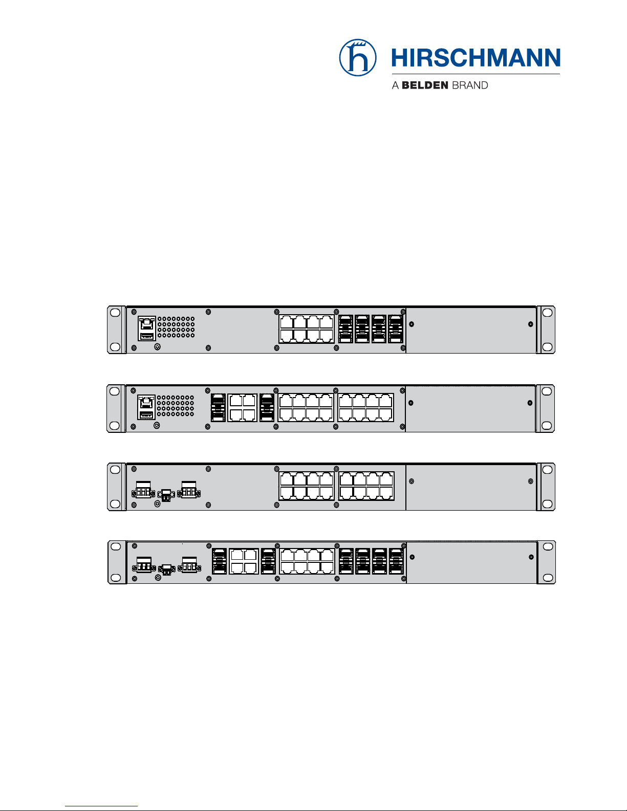
GRS 1020
GRS 1030
GRS 1120
GRS 1130

The naming of copyrighted trademarks in this manual, even when not specially indicated, should
not be taken to mean that these names may be considered as free in the sense of the trademark
and tradename protection law and hence that they may be freely used by anyone.
© 2017 Hirschmann Automation and Control GmbH
Manuals and software are protected by copyright. All rights reserved. The copying, reproduction,
translation, conversion into any electronic medium or machine scannable form is not permitted,
either in whole or in part. An exception is the preparation of a backup copy of the software for
your own use.
The performance features described here are binding only if they have been expressly agreed
when the contract was made. This document was produced by Hirschmann Automation and
Control GmbH according to the best of the company's knowledge. Hirschmann reserves the right
to change the contents of this document without prior notice. Hirschmann can give no guarantee
in respect of the correctness or accuracy of the information in this document.
Hirschmann can accept no responsibility for damages, resulting from the use of the network
components or the associated operating software. In addition, we refer to the conditions of use
specified in the license contract.
You can get the latest version of this manual on the Internet at the Hirschmann product site
(www.hirschmann.com).
Hirschmann Automation and Control GmbH
Stuttgarter Str. 45-51
72654 Neckartenzlingen
Germany
InstallationGRS1020/1120/1030/1130

Installation GRS1020/1120/1030/1130
Release 03 01/2017
3
Contents
Safety instructions 5
About this Manual 14
Legend 14
1 Description 15
1.1 General device description 15
1.2 Device name and product code 16
1.3 Combination options 20
1.4 Device views 21
1.4.1 Front view 21
1.4.2 Rear view 22
1.5 Power supply 23
1.5.1 Supply voltage with the characteristic value C 23
1.5.2 Supply voltage with the characteristic value M 23
1.6 Ethernet ports 23
1.6.1 Gigabit combo port 23
1.6.2 10/100 Mbit/s twisted pair port 25
1.6.3 100 Mbit/s F/O port (optional) 25
1.7 Display elements 26
1.7.1 Device state 26
1.7.2 Port status 27
1.7.3 Media module status 28
1.8 Management interfaces 29
1.8.1 V.24 interface (external management) 29
1.8.2 USB interface 29
1.9 Signal contact 30
2 Installation 31
2.1 Checking the package contents 31
2.2 Installing and grounding the device 31
2.3 Installing an SFP transceiver (optional) 35
2.4 Connecting the terminal blocks 36
2.4.1 Supply voltage with the characteristic value C 36
2.4.2 Supply voltage with the characteristic value M 37
2.4.3 Signal contact 38
2.5 Mounting a media module (optional) 39

4
Installation GRS1020/1120/1030/1130
Release 03 01/2017
2.6 Operating the device 40
2.7 Connecting data cables 40
2.8 Filling out the inscription label 40
3 Making basic settings 41
4 Monitoring the ambient air temperature 42
5 Maintenance and service 43
6Disassembly 44
6.1 Removing the device 44
6.2 Removing an SFP transceiver (optional) 44
6.3 Removing a media module (optional) 45
7 Technical data 46
A Further Support 58

Installation GRS1020/1120/1030/1130
Release 03 01/2017
5
Safety instructions
General safety instructions
You operate this device with electricity. Improper usage of the device
entails the risk of physical injury or significant property damage. The
proper and safe operation of this device depends on proper handling
during transportation, proper storage and installation, and careful
operation and maintenance procedures.
Before connecting any cable, read this document, and the safety
instructions and warnings.
Operate the device with undamaged components exclusively.
The device is free of any service components. In case of a damaged
or malfunctioning the device, turn off the supply voltage and return the
device to Hirschmann for inspection.
Qualification requirements for personnel
Only allow qualified personnel to work on the device.
Qualified personnel have the following characteristics:
Qualified personnel are properly trained. Training as well as practical
knowledge and experience make up their qualifications. This is the
prerequisite for grounding and labeling circuits, devices, and systems
in accordance with current standards in safety technology.
Qualified personnel are aware of the dangers that exist in their work.
Qualified personnel are familiar with appropriate measures against
these hazards in order to reduce the risk for themselves and others.
Qualified personnel receive training on a regular basis.
Correct usage
Only use the device for those purposes specified in the catalog and in the
technical description. Only operate the device with external devices and
components that are recommended and permitted by the manufacturer.
The proper and safe operation of this product depends on proper handling
during transport, proper storage, assembly and installation, and
conscientious operation and maintenance procedures.
National and international safety regulations
Verify that the electrical installation meets local or nationally applicable
safety regulations.

6
Installation GRS1020/1120/1030/1130
Release 03 01/2017
Supply voltage
The supply voltage is electrically isolated from the housing.
Every time you connect the electrical conductors, make sure that the
following requirements are met:
The power supply conforms to overvoltage category I or II.
The power supply has an easily accessible disconnecting device
(e.g., a switch or a plug). This disconnecting device is clearly
identified. So in the case of an emergency, it is clear which
disconnecting device belongs to which power supply cable.
The electrical wires are voltage-free.
The ground screw on the back of the device is connected to the
protective conductor.
Supply with AC voltage:
A fuse is located in the outer conductor of the power supply.
The neutral conductor is on ground potential at both voltage inputs.
Otherwise, a fuse is also located in the neutral conductor.
Regarding the properties of this fuse:
See “General technical data” on page 46.
Supply with DC voltage:
A fuse suitable for DC voltage is located in the plus conductor of the
power supply.
The minus conductor is on ground potential. Otherwise, a fuse is
also located in the minus conductor.
Regarding the properties of this fuse:
See “General technical data” on page 46.
Supply with DC voltage: the fuse is suitable for a DC voltage.
If the neutral conductor (AC) or the negative conductor (DC) is not
grounded: there is a fuse in each of the two wires.
Supply with AC voltage:
The wire diameter of the power supply cable is at least 0.75 mm²
(North America: AWG18) on the supply voltage input.
Supply with DC voltage:
The wire diameter of the power supply cable is at least 1 mm²
(North America: AWG16) on the supply voltage input.
The cross-section of the protective conductor is the same size as
or bigger than the cross-section of the power supply cables.
The cables used are permitted for the temperature range of the
application case.
Relevant for North America:
For use in Class 2 circuits, the copper wire conforms to class 1,
140/167 °F or 167 °F (60/75 °C or 75 °C).

Installation GRS1020/1120/1030/1130
Release 03 01/2017
7
Verify that the electrical installation meets locally or nationally
applicable safety regulations.
Use undamaged parts.
Internal fuses are triggered only in the case of a detected error in the
device. In case of damage or malfunction of the device, turn off the
supply voltage and return the device to the plant for inspection.
Only switch on the device when the housing is closed.
First connect the ground screw on the back of the device with the
protective conductor before you set up the other connections. When
removing the connections, you remove the protective conductor last.
For supply voltage connections with protective conductor connection:
First connect the protective conductor before connecting the wires for
the supply voltage.
If your device comprises a 2nd supply voltage connection of this type:
First connect the protective conductor before connecting the wires for
the supply voltages.
Shielded ground
The shielded ground wire of the twisted pairs cables is connected to the
front panel as a conductor.
Beware of possible short circuits when connecting a cable section with
conductive shield braiding.
WARNING
ELECTRIC SHOCK
Start connecting the electrical wires only if all the above safety
requirements are fulfilled.
Failure to follow these instructions can result in death, serious injury,
or equipment damage.
8
Installation GRS1020/1120/1030/1130
Release 03 01/2017
Device casing
Only technicians authorized by the manufacturer are permitted to open
the casing.
Keep the ventilation slits free to ensure good air circulation.
Make sure there is at least 3.94 inches (10 cm) of space in front of the
ventilation slits of the housing.
Do not touch the housing during operation or shortly after switching off
the device. Hot surfaces can cause injury.
Mount the device horizontally in a cabinet or vertically on a flat surface.
Operating the device as a table unit is inadmissible.
See “Installing and grounding the device” on page 31.
Operating the device in the maximum surrounding air temperature and
stacking devices: When installing the device, make sure there is at
least one free rack space (approx. 5 cm) above the device, because
heat is discharged via the housing of the device.
If you are operating the device in a 19" switch cabinet: install
sliding/mounting rails for supporting the weight of the device.
WARNING
ELECTRIC SHOCK
Never insert sharp objects (small screwdrivers, wires, etc.) into the inside of
the device.
Never insert sharp objects (small screwdrivers, wires, etc.) into the
connection terminals for electric conductors, and do not touch the terminals.
Install this device solely in a switch cabinet or in an operating site with
restricted access, to which maintenance staff have exclusive access.
Failure to follow these instructions can result in death, serious injury,
or equipment damage.
WARNING
FIRE HAZARD
Install the device in a fire protected shell if you are mounting it vertically.
Failure to follow these instructions can result in death, serious injury,
or equipment damage.

Installation GRS1020/1120/1030/1130
Release 03 01/2017
9
Operating conditions
Operate the device at the specified ambient temperature (temperature of
the ambient air at a distance of 2 inches (5 cm) from the device) and at
the specified relative humidity exclusively.
When you are selecting the installation location, make sure you
observe the climatic threshold values specified in the technical data.
Use the device in an environment with a maximum pollution degree
that complies with the specifications in the technical data.
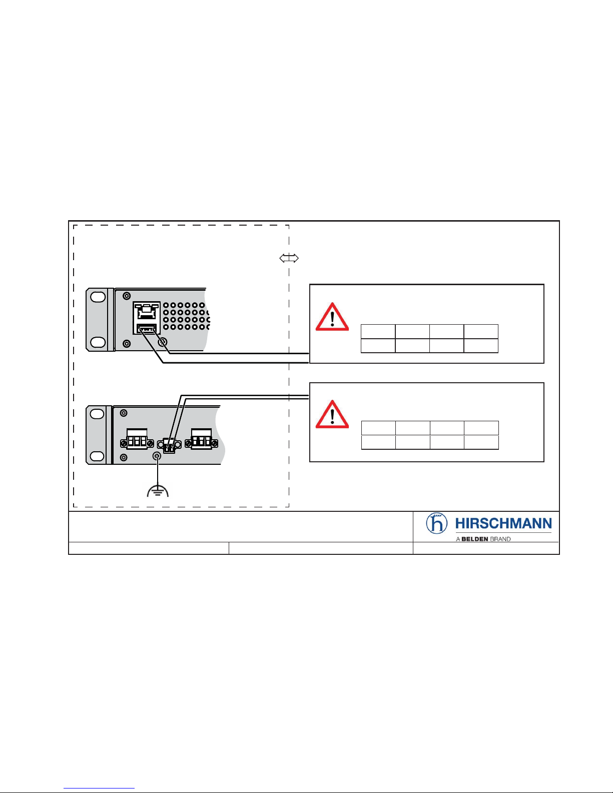
Relevant for use in explosion hazard areas (Hazardous
Locations, Class I, Division 2):
The relay connections are to be installed and used within their entity
parameters as per Control Drawing 000192283DNR. Details see the next
two pages.
Avertissement - Risque d'explosion - Ne pas débrancher tant que le
circuit est sous tension à moins que l'emplacement soit connu pour ne
contenir aucune concentration de gaz inflammable.
Avertissement - Risque d'explosion - La substitution de tout composant
peut rendre ce matériel incompatible pour une utilisation en classe I,
division 2.
10
Installation GRS1020/1120/1030/1130
Release
03
01/2017
CONTROL DRAWING - GREYHOUND series for use in HAZARDOUS LOCATIONS
Class I, Division 2, Groups A, B, C, D
Document No.:
000192283DNR
Rev.: 0 Page 1/2
The earth conductor must be
at least of the same wire size
(mm² or AWG) as the supply
conductors.
Any GREYHOUND-GRS1xxx device
Class I, Division 2
Groups A, B, C, D
Hazardous Location
1RQLQFHQGLYH¿HOGZLULQJSDUDPHWHUV
THE USB POWER SUPPLY CONTACTS DEPEND
ON THE FOLLOWING PARAMETERS: *)
Front view
Back view
Ordinary location,
non-hazardous area,
non-explosive atmosphere
V
OC
I
SC
C
a
L
a
9 $ 10 μF 10 μH
V
max
I
max
C
a
L
a
9 90 mA 3 nF 1 μH
1RQLQFHQGLYH¿HOGZLULQJSDUDPHWHUV
THE RELAY TERMINALS DEPEND ON THE
FOLLOWING PARAMETERS: *)
FAULT contacts
USB pin 1
USB pin 4
Installation GRS1020/1120/1030/1130
Release
03
01/2017
11
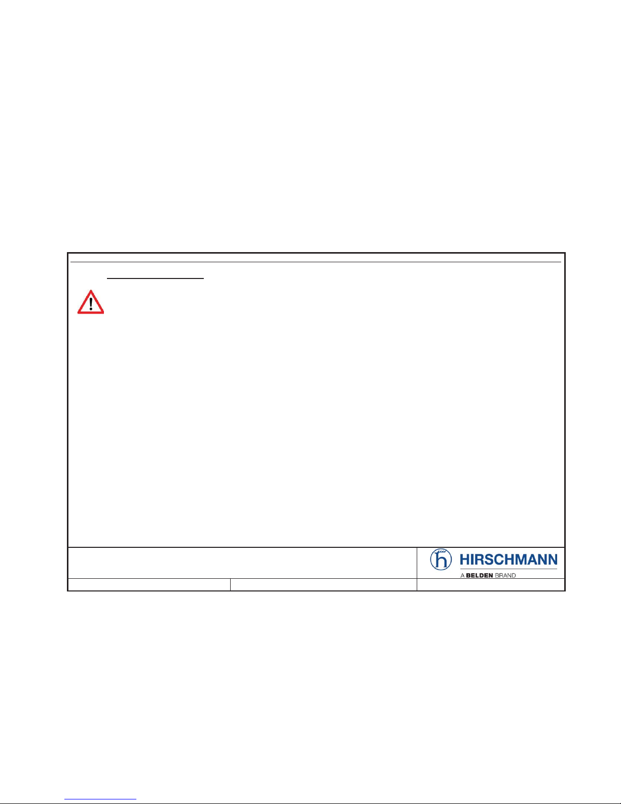
SUITABLE FOR USE IN CLASS I DIVISION 2 GROUPS A, B ,C ,D HAZARDOUS LOCATIONS, OR NON-HAZARDOUS LOCATIONS ONLY.
For use in HAZARDOUS LOCATIONS only allowed for model numbers which are labelled accordingly.
1RQLQFHQGLYH¿HOGZLULQJFLUFXLWVPXVWEHZLUHGLQDFFRUGDQFHZLWKWKH
National Electrical Code (NEC), NFPA 70, article 501;CEC, Appendix J, Annex J18.
86%$1'5(/$<&217$&76)$8/7,QVWDOOSHU&RQWURO'UDZLQJ'15
WARNING – EXPLOSION HAZARD – SUBSTITUTION OF ANY COMPONENTS MAY IMPAIR SUITABILITY FOR CLASS I DIVISION 2.
WARNING – EXPLOSION HAZARD – DO NOT DISCONNECT EQUIPMENT WHILE THE CIRCUIT IS LIVE OR UNLESS THE AREA IS
KNOWN TO BE FREE OF IGNITABLE CONCENTRATIONS.
*) Notes:
7KHQRQLQFHQGLYH¿HOGZLULQJFLUFXLWFRQFHSWDOORZVLQWHUFRQQHFWLRQRIQRQLQFHQGLYH¿HOGZLULQJDSSDUDWXVDQGDVVRFLDWHGQRQLQFHQGLYH
¿HOGZLULQJDSSDUDWXVXVLQJDQ\RIWKHZLULQJPHWKRGVSHUPLWWHGIRUXQFODVVL¿HGORFDWLRQVZKHQFHUWDLQSDUDPHWULFFRQGLWLRQVDUHPHW
Capacity: C
a
&i + C
&DEOH
; Inductivity: La/i + L
&DEOH
The PD[LPXPFDEOHOHQJWK has to be determined as follows:
DPD[FDEOHOHQJWK/
0
- Li&DEOHCRUPD[FDEOHOHQJWK/a - Li&DEOHL
(“Cable
L
” denotes the inductance per unit length of used cable) and
EPD[&DEOH/HQJWK&
a
- Ci&DEOHC
(“Cable
C
” denotes the capacitance per unit length of used cable).
The lower value of (a) and (b) is to apply.
0DQXIDFWXUHGLQ1HFNDUWHQ]OLQJHQ*HUPDQ\E\+LUVFKPDQQ$XWRPDWLRQDQG&RQWURO*PE+
DOM: ww/yyyy (Date of manufacture w - week, y - year. Refer to the device label.)
CONTROL DRAWING - GREYHOUND series for use in HAZARDOUS LOCATIONS
Class I, Division 2, Groups A, B, C, D
Document No.:
000192283DNR
Rev.: 0 Page 2/2

12
Installation GRS1020/1120/1030/1130
Release 03 01/2017
CE marking
The labeled devices comply with the regulations contained in the following
European directive(s):
In accordance with the above-named EU directive(s), the EU conformity
declaration will be at the disposal of the relevant authorities at the
following address:
Hirschmann Automation and Control GmbH
Stuttgarter Str. 45-51
72654 Neckartenzlingen
Germany
www.hirschmann.com
The product can be used in the industrial sector.
Interference immunity: EN 61000-6-2
Emitted interference: EN 55022
Reliability: EN 60950-1
Warning! This is a class A device. This device can cause interference in
living areas, and in this case the operator may be required to take
appropriate measures.
Note: The assembly guidelines provided in these instructions must be
strictly adhered to in order to observe the EMC threshold values.
Device variant Directive
All variants 2011/65/EU (RoHS)
Directive of the European Parliament and of the Council on the
restriction of the use of certain hazardous substances in
electrical and electronic equipment.
All variants 2014/30/EU (EMC)
Directive of the European Parliament and the council for
standardizing the regulations of member states with regard to
electromagnetic compatibility.
Only for device variants
featuring supply voltage with
the characteristic value M:
2014/35/EU
Directive of the European Parliament and the council for
standardizing the regulations of member states with regard to
electrical equipment for use within specific voltage limits.

Installation GRS1020/1120/1030/1130
Release 03 01/2017
13
LED or laser components
LED or LASER components according to IEC 60825-1 (2014):
CLASS 1 LASER PRODUCT
CLASS 1 LED PRODUCT
FCC note:
This device complies with part 15 of the FCC rules. Operation is subject
to the following two conditions: (1) this device may not cause harmful
interference; (2) this device must accept any interference received,
including interference that may cause undesired operation.
Appropriate testing has established that this device fulfills the
requirements of a class A digital device in line with part 15 of the FCC
regulations.
These requirements are designed to provide sufficient protection against
interference when the device is being used in a business environment.
The device creates and uses high frequencies and can also radiate these
frequencies. If it is not installed and used in accordance with this
operating manual, it can cause radio transmission interference. The use
of this device in a residential area can also cause interference, and in this
case the user is obliged to cover the costs of removing the interference.
Recycling note
After usage, this device must be disposed of properly as electronic waste,
in accordance with the current disposal regulations of your county, state,
and country.

14
Installation GRS1020/1120/1030/1130
Release 03 01/2017
About this Manual
The “Installation” user manual contains a device description, safety
instructions, a description of the display, and the other information that you
need to install the device.
The documentation for your device is made up of the following documents:
General safety instructions
Installation user manual
Basic Configuration user manual
Redundancy Configuration user manual
Reference manual for the graphical user interface
Command Line Interface reference manual
The Industrial HiVision Network Management software provides you with
additional options for smooth configuration and monitoring:
ActiveX control for SCADA integration
Auto-topology discovery
Browser interface
Client/server structure
Event handling
Event log
Simultaneous configuration of multiple devices
Graphical user interface with network layout
SNMP/OPC gateway
Legend
The symbols used in this manual have the following meanings:
Listing
Work step
Subheading

Installation GRS1020/1120/1030/1130
Release 03 01/2017
15
1 Description
1.1 General device description
You can choose from between a wide range of variants. You have the option
to set up your device individually based on different criteria:
Number of ports
Transmission speed
Types of connectors
Temperature range
Supply voltage range
Certifications
The GREYHOUND devices are designed for the special requirements of
industrial automation. They meet the relevant industry standards, provide
very high operational reliability, even under extreme conditions, and also
long-term reliability and flexibility.
The devices allow you to set up switched industrial Ethernet networks that
conform to the IEEE 802.3 standard.
The devices work without a fan.
The following installation options are available:
19" switch cabinet
Flat surface mounting
You have the option of choosing various media to connect to the terminal
devices and other network components:
twisted pair cable
multimode F/O
singlemode F/O
The ring redundancy concept allows the network to be reconfigured quickly
after a failure.
Product configuration data can be provided by:
diagnosis displays
Displaying the operating parameters
There are convenient options for managing the device. Administer your
devices via:
a Web browser
Telnet
HiDiscovery (Software for putting the device into operation)
network management software (e.g. Industrial HiVision)
a V.24 interface (locally on the device)

16
Installation GRS1020/1120/1030/1130
Release 03 01/2017
The devices provide you with a large range of functions, which the manuals
for the operating software inform you about. You will find these manuals as
PDF files on the Internet on the Hirschmann product pages
(www.hirschmann.com).
The Hirschmann network components help you ensure continuous
communication across all levels of the company.
1.2 Device name and product code
The device name corresponds to the product code. The product code is
made up of characteristics with defined positions. The characteristic values
stand for specific product properties.
Item Characteristic Character
istic value
Description
1 ... 3 Product GRS GREYHOUND Switch
4 Series 1 GREYHOUND Series
5 Position of the ports
and power supply
inputs
0 Ethernet ports: front of device
Power supply inputs: back of device
1 Ethernet ports: back of device
Power supply inputs: front of device
6 Data rate 2 10/100 Mbit/s
3 10/100 Mbit/s
with 100/1000 Mbit/s uplink ports
7 PoE support 0 None
8 (hyphen) –
9 ... 12 Configuration of the
ports
16T9 16 × RJ45 socket for 10/100 Mbit/s twisted pair
connections
8T8Z 8 × RJ45 socket for 10/100 Mbit/s twisted pair
connections
8 × SFP slot for 100 Mbit/s F/O connections
13 Temperature range S Standard 0 °C ... +60 °C (+32 °F ...
+140 °F)
T Extended −40 °F ... +158 °F (−40 °C
... +70 °C)
E Extended with
conformal coating
−40 °F ... +158 °F (−40 °C
... +70 °C)
14 Supply voltage 1 C Voltage input
Rated voltage range DC
24 V ... 48 V
M Voltage input
Rated voltage range DC
110 V ... 250 V
Rated voltage range AC
110 V ... 240 V, 50 Hz ... 60 Hz
Table 1: Device name and product code

Installation GRS1020/1120/1030/1130
Release 03 01/2017
17
15 Supply voltage 2 C Voltage input
Rated voltage range DC
24 V ... 48 V
M Voltage input
Rated voltage range DC
110 V ... 250 V
Rated voltage range AC
110 V ... 240 V, 50 Hz ... 60 Hz
9 None
16 ... 17 Certificates and
declarations
You will find detailed information on the certificates and
declarations applying to your device in a separate overview.
See table 2 on page 18.
18 ... 19 Customer-specific
version
HH Hirschmann standard
20 Hardware configuration S Standard
21 Software configuration E Entry (Hirschmann Standard)
22 ... 23 Software level 2S HiOS Layer 2 Standard
24 ... 28 Software version 04.1. Software-Version 04.1
XX.X. Current software version
Item Characteristic Character
istic value
Description
Table 1: Device name and product code

18
Installation GRS1020/1120/1030/1130
Release
03
01/2017
Application case Certificates and declarations Characteristic value
a
a. X = Approval or self-declaration is present
(X) = Approval or self-declaration is being prepared
Z9 Y9 X9 V9 VY VU VT U9 UY UX UT T9 TY
Standard applications CE X X X X X X X X X X X X X
EN 60950-1 X X X X X X X X X X X X X
EN 61131-2 X X X X X X X X X X X X X
FCC X X X X X X X X X X X X X
ISA 12.12.01 – Class I, Div. 2 X X
cUL 60950-1 X X X X X X X X X
Substation applications IEC 61850-3 X X X X
IEEE1613 X X X X
Navy applications DNV GL (X) (X) (X) (X) (X)
Railway applications
(trackside)
EN 50121-4 X X X X
Table 2: Assignment: application cases, certificates and declarations, characteristic values
 Loading...