

Page 1

Installation GREYHOUND Switch
Release 01 04/2016
Technical support
https://hirschmann-support.belden.eu.com
User Manual
Installation
GREYHOUND Switch - GRS1042/GRS1142
GREYHOUND Power Supply Unit - GPS1/GPS2/GPS3
GREYHOUND Media Module - GMM20/30/32/40/42
Page 2

The naming of copyrighted trademarks in this manual, even when not specially indicated, should
not be taken to mean that these names may be considered as free in the sense of the trademark
and tradename protection law and hence that they may be freely used by anyone.
© 2016 Hirschmann Automation and Control GmbH
Manuals and software are protected by copyright. All rights reserved. The copying, reproduction,
translation, conversion into any electronic medium or machine scannable form is not permitted,
either in whole or in part. An exception is the preparation of a backup copy of the software for
your own use.
The performance features described here are binding only if they have been expressly agreed
when the contract was made. This document was produced by Hirschmann Automation and
Control GmbH according to the best of the company's knowledge. Hirschmann reserves the right
to change the contents of this document without prior notice. Hirschmann can give no guarantee
in respect of the correctness or accuracy of the information in this document.
Hirschmann can accept no responsibility for damages, resulting from the use of the network
components or the associated operating software. In addition, we refer to the conditions of use
specified in the license contract.
You can get the latest version of this manual on the Internet at the Hirschmann product site
(www.hirschmann.com).
Hirschmann Automation and Control GmbH
Stuttgarter Str. 45-51
72654 Neckartenzlingen
Germany
Tel.: +49 1805 141538
GREYHOUND Switch
Page 3

Installation GREYHOUND Switch
Release 01 04/2016
3
Contents
Safety instructions 5
About this Manual 12
Legend 12
1 Description 13
1.1 General device description 13
1.2 Device name and product code 15
1.2.1 Basic device 15
1.2.2 Power supply units 17
1.2.3 Media modules 18
1.3 Device views 20
1.3.1 GRS1042 20
1.3.2 GRS1142 21
1.3.3 Power supply units 22
1.3.4 Media modules 23
1.4 Power supply 25
1.5 Signal contact 26
1.6 Ethernet ports 27
1.6.1 1/2.5 Gbit/s F/O port 27
1.6.2 100/1000 Mbit/s F/O port 27
1.6.3 100 Mbit/s F/O port 27
1.6.4 10/100/1000 Mbit/s twisted pair port 28
1.6.5 Support of PoE(+) 28
1.6.6 Out-of-band management port 29
1.7 Pin assignments 29
1.8 Display elements 30
1.8.1 Device state 30
1.8.2 Port state 32
1.8.3 Media module status 34
1.9 Management interfaces 36
1.9.1 V.24 interface (external management) 36
1.9.2 USB interface 37
1.9.3 SD card interface 38
2 Installation 39
2.1 Checking the package contents 39
2.2 Installing the SD card (optional) 39
Page 4

4
Installation GREYHOUND Switch
Release 01 04/2016
2.3 Mounting the cover panel and the power supply unit
(optional) 40
2.3.1 Mounting the cover panel 40
2.3.2 Mounting the power supply unit 40
2.4 Mounting a media module (optional) 41
2.5 Installing and grounding the device 42
2.6 Connecting the terminal blocks 46
2.6.1 Supply voltage 46
2.6.2 Signal contact 49
2.7 Installing an SFP transceiver (optional) 50
2.8 Operating the device 51
2.9 Connecting data cables 51
2.10 Filling out the inscription label 51
3 Making basic settings 52
4 Monitoring the ambient air temperature 53
5 Maintenance and service 54
6Disassembly 55
6.1 Removing a power supply unit 55
6.2 Removing a media module 56
6.3 Removing an SFP transceiver 56
6.4 Removing the device 57
7 Technical data 58
7.1 General technical data 58
7.1.1 Basic device 58
7.1.2 Power supply units 59
7.1.3 Media modules 61
7.2 Dimension drawings 62
7.2.1 Basic device 62
7.2.2 Power supply units 63
7.2.3 Media modules 64
A Further Support 75
Page 5
Installation GREYHOUND Switch
Release 01 04/2016
5
Safety instructions
General safety instructions
You operate this device with electricity. Improper usage of the device
entails the risk of physical injury or significant property damage. The
proper and safe operation of this device depends on proper handling
during transportation, proper storage and installation, and careful
operation and maintenance procedures.
Before connecting any cable, read this document, and the safety
instructions and warnings.
Operate the device with undamaged components exclusively.
The device is free of any service components. In case of a damaged
or malfunctioning the device, turn off the supply voltage and return the
device to Hirschmann for inspection.
Qualification requirements for personnel
Only allow qualified personnel to work on the device.
Qualified personnel have the following characteristics:
Qualified personnel are properly trained. Training as well as practical
knowledge and experience make up their qualifications. This is the
prerequisite for grounding and labeling circuits, devices, and systems
in accordance with current standards in safety technology.
Qualified personnel are aware of the dangers that exist in their work.
Qualified personnel are familiar with appropriate measures against
these hazards in order to reduce the risk for themselves and others.
Qualified personnel receive training on a regular basis.
WARNING
UNCONTROLLED MACHINE ACTIONS
To avoid uncontrolled machine actions caused by data loss, configure all
the data transmission devices individually.
Before you start any machine which is controlled via data transmission, be
sure to complete the configuration of all data transmission devices.
Failure to follow these instructions can result in death, serious injury,
or equipment damage.
Page 6

6
Installation GREYHOUND Switch
Release 01 04/2016
Correct usage
Only use the device for those purposes specified in the catalog and in the
technical description. Only operate the device with external devices and
components that are recommended and permitted by the manufacturer.
The proper and safe operation of this product depends on proper handling
during transport, proper storage, assembly and installation, and
conscientious operation and maintenance procedures.
National and international safety regulations
Verify that the electrical installation meets local or nationally applicable
safety regulations.
Supply voltage
The supply voltage is electrically isolated from the housing.
Every time you connect the electrical conductors, make sure that the
following requirements are met:
The power supply conforms to overvoltage category I or II.
The power supply has an easily accessible disconnecting device
(e.g., a switch or a plug). This disconnecting device is clearly
identified. So in the case of an emergency, it is clear which
disconnecting device belongs to which power supply cable.
The electrical wires are voltage-free.
The ground screw on the back of the device is connected to the
protective conductor.
Supply with AC voltage:
A fuse is located in the outer conductor of the power supply.
The neutral conductor is on ground potential at both voltage inputs.
Otherwise, a fuse is also located in the neutral conductor.
Regarding the properties of this fuse:
See “General technical data” on page 58.
Supply with DC voltage:
A fuse suitable for DC voltage is located in the plus conductor of the
power supply.
The minus conductor is on ground potential. Otherwise, a fuse is
also located in the minus conductor.
Regarding the properties of this fuse:
See “General technical data” on page 58.
Supply with DC voltage: the fuse is suitable for a DC voltage.
If the neutral conductor (AC) or the negative conductor (DC) is not
grounded: there is a fuse in each of the two wires.
Supply with AC voltage:
The wire diameter of the power supply cable is at least 0.75 mm²
(North America: AWG18) on the supply voltage input.
Page 7
Installation GREYHOUND Switch
Release 01 04/2016
7
Supply with DC voltage:
The wire diameter of the power supply cable is at least 1 mm²
(North America: AWG16) on the supply voltage input.
The cross-section of the protective conductor is the same size as
or bigger than the cross-section of the power supply cables.
The cables used are permitted for the temperature range of the
application case.
Relevant for North America:
For use in Class 2 circuits, the copper wire conforms to class 1,
60/75 °C or 75 °C.
Verify that the electrical installation meets locally or nationally
applicable safety regulations.
Use undamaged parts.
Internal fuses are triggered only in the case of a detected error in the
device. In case of damage or malfunction of the device, turn off the
supply voltage and return the device to the plant for inspection.
Only switch on the device when the housing is closed.
First connect the ground screw on the back of the device with the
protective conductor before you set up the other connections. When
removing the connections, you remove the protective conductor last.
For supply voltage connections with protective conductor connection:
First connect the protective conductor before connecting the wires for
the supply voltage.
If your device comprises a 2nd supply voltage connection of this type:
First connect the protective conductor before connecting the wires for
the supply voltages.
Shielded ground
The shielded ground wire of the twisted pairs cables is connected to the
front panel as a conductor.
Beware of possible short circuits when connecting a cable section with
conductive shield braiding.
WARNING
ELECTRIC SHOCK
Start connecting the electrical wires only if all the above safety
requirements are fulfilled.
Failure to follow these instructions can result in death, serious injury,
or equipment damage.
Page 8
8
Installation GREYHOUND Switch
Release 01 04/2016
ESD Guidelines
The modules are equipped with electrostatically sensitive components.
These can be destroyed, or their life cycles reduced, by the effects of an
electrical field or by a charge equalization if the connections are touched.
You will find information about electrostatically endangered assemblies in
DIN EN 61340-5-1 (2007-08) and DIN EN 61340-5-2 (2007-08).
Device casing
WARNING
ELECTRIC SHOCK
Never insert sharp objects (small screwdrivers, wires, etc.) into the inside of
the device.
Never insert sharp objects (small screwdrivers, wires, etc.) into the
connection terminals for electric conductors, and do not touch the terminals.
Install this device solely in a switch cabinet or in an operating site with
restricted access, to which maintenance staff have exclusive access.
Failure to follow these instructions can result in death, serious injury,
or equipment damage.
WARNING
FIRE HAZARD
Install the device in a fire protected shell if you are mounting it vertically.
Failure to follow these instructions can result in death, serious injury,
or equipment damage.
Page 9

Installation GREYHOUND Switch
Release 01 04/2016
9
Only technicians authorized by the manufacturer are permitted to open
the casing.
Keep the ventilation slits free to ensure good air circulation.
Make sure there is at least 3.94 inches (10 cm) of space in front of the
ventilation slits of the housing.
Do not touch the housing during operation or shortly after switching off
the device. Hot surfaces can cause injury.
Mount the device horizontally in a cabinet or vertically on a flat surface.
Operating the device as a table unit is inadmissible.
See “Installing and grounding the device” on page 42.
Operating the device in the maximum surrounding air temperature and
stacking devices: When installing the device, make sure there is at
least one free rack space (approx. 5 cm) above the device, because
heat is discharged via the housing of the device.
If you are operating the device in a 19" switch cabinet: install
sliding/mounting rails for supporting the weight of the device.
Operating conditions
Operate the device at the specified ambient temperature (temperature of
the ambient air at a distance of 2 inches (5 cm) from the device) and at
the specified relative humidity exclusively.
When you are selecting the installation location, make sure you
observe the climatic threshold values specified in the technical data.
Use the device in an environment with a maximum pollution degree
that complies with the specifications in the technical data.
Page 10

10
Installation GREYHOUND Switch
Release 01 04/2016
CE marking
The labeled devices comply with the regulations contained in the following
European directive(s):
In accordance with the above-named EU directive(s), the EU conformity
declaration will be at the disposal of the relevant authorities at the
following address:
Hirschmann Automation and Control GmbH
Stuttgarter Str. 45-51
72654 Neckartenzlingen
Germany
Tel.: +49 1805 141538
The product can be used in the industrial sector.
Interference immunity: EN 61000-6-2
Emitted interference: EN 55022
Reliability: EN 60950-1
Warning! This is a class A device. This device can cause interference in
living areas, and in this case the operator may be required to take
appropriate measures.
Note: The assembly guidelines provided in these instructions must be
strictly adhered to in order to observe the EMC threshold values.
LED or laser components
LED or LASER components according to IEC 60825-1 (2014):
CLASS 1 LASER PRODUCT
CLASS 1 LED PRODUCT
Device variant Directive
All variants 2011/65/EU (RoHS)
Directive of the European Parliament and of the Council on the
restriction of the use of certain hazardous substances in
electrical and electronic equipment.
All variants 2014/30/EU
Directive of the European Parliament and the council for
standardizing the regulations of member states with regard to
electromagnetic compatibility.
Only for device variants
featuring supply voltage with
characteristic value H:
2014/35/EU
Directive of the European Parliament and the council for
standardizing the regulations of member states with regard to
electrical equipment for use within specific voltage limits.
Page 11

Installation GREYHOUND Switch
Release 01 04/2016
11
FCC note:
This device complies with part 15 of the FCC rules. Operation is subject
to the following two conditions: (1) this device may not cause harmful
interference; (2) this device must accept any interference received,
including interference that may cause undesired operation.
Appropriate testing has established that this device fulfills the
requirements of a class A digital device in line with part 15 of the FCC
regulations.
These requirements are designed to provide sufficient protection against
interference when the device is being used in a business environment.
The device creates and uses high frequencies and can also radiate these
frequencies. If it is not installed and used in accordance with this
operating manual, it can cause radio transmission interference. The use
of this device in a residential area can also cause interference, and in this
case the user is obliged to cover the costs of removing the interference.
Recycling note
After usage, this device must be disposed of properly as electronic waste,
in accordance with the current disposal regulations of your county, state,
and country.
Page 12

12
Installation GREYHOUND Switch
Release 01 04/2016
About this Manual
The “Installation” user manual contains a device description, safety
instructions, a description of the display, and the other information that you
need to install the device.
Legend
The symbols used in this manual have the following meanings:
Listing
Work step
Subheading
Page 13
Installation GREYHOUND Switch
Release 01 04/2016
13
1 Description
1.1 General device description
The GREYHOUND devices are designed for the special requirements of
industrial automation. They meet the relevant industry standards, provide
very high operational reliability, even under extreme conditions, and also
long-term reliability and flexibility.
The devices allow you to set up switched industrial Ethernet networks that
conform to the IEEE 802.3 standard.
Basic device
You can choose from between a wide range of variants. You have the
option to set up your device individually based on different criteria:
Number of ports
Transmission speed
Types of connectors
Temperature range
Supply voltage range
Certifications
You have numerous options of combining the device characteristics. You
can determine the possible combinations using the configurator which is
available in the Belden E-Catalog (www.e-catalog.beldensolutions.com)
on the web page of the device.
GRS1042
GRS1142
Page 14
14
Installation GREYHOUND Switch
Release 01 04/2016
Power supply units
You have the option to select either 1 or 2 power supply units with different
input voltages:
Low Voltage / Power over Ethernet PoE(+)
High Voltage
You obtain the power supply units as accessories.
See “Order number” on page 70.
Media modules
You have the option to select either 1 or 2 media modules. By using a
media module, you obtain up to 8 additional Fast and/or Gigabit Ethernet
ports.
You obtain the media modules as accessories.
See “Order number” on page 70.
GREYHOUND Power Supply Unit
GREYHOUND Media Module
Page 15

Installation GREYHOUND Switch
Release 01 04/2016
15
1.2 Device name and product code
The device name corresponds to the product code. The product code is
made up of characteristics with defined positions. The characteristic values
stand for specific product properties.
1.2.1 Basic device
Item Characteristic Character
istic value
Description
1 ... 3 Product GRS GREYHOUND Switch
4 Series 1 GREYHOUND Series
5 Position of the ports
and power supply
inputs
0 Ethernet ports: front of device
Power supply inputs: back of device
1 Ethernet ports and power supply inputs:
rear of device
6 Data rate 4 (10)/100/1000Mbit/s with 2.5 Gbit/s uplink ports
7 Hardware type 2 PoE(+) support
8 (hyphen) –
9 ... 12 Configuration of the
ports
AT2Z 10 ×
2×
RJ45 socket for 10/100/1000 Mbit/s
Twisted Pair connections
SFP slot for 1/2.5 Gbit/s F/O connections
6T6Z 6 ×6×RJ45 socket for 10/100/1000 Mbit/s
Twisted Pair connections
4 × SFP slots for 1/2.5 Gbit/s F/O
connections and
2 × SFP slots for 100/1000 Mbit/s
connections
13 Temperature range S Standard 0 °C ... +60 °C
(+32 °F ... +140 °F)
T Extended −40 °F ... +158 °F
(−40 °C ... +70 °C)
E Extended with
conformal coating
−40 °F ... +158 °F
(−40 °C ... +70 °C)
14 Supply voltage 1 L Voltage input: low voltage
Rated voltage range DC
24 ... 48 V
48 V... 54 V
Can be combined with power supply unit
with characteristic value C or P
H Voltage input: high voltage
Rated voltage range DC
60 V ... 250 V
Rated voltage range AC
110 V ... 240 V, 50 Hz ... 60 Hz
Can be combined with power supply unit
with characteristic value K
15 Supply voltage 2 See position 14
16 Cover panel for power
supply unit slot
0None
1 1 × cover panel for slot 2
Page 16

16
Installation GREYHOUND Switch
Release 01 04/2016
17 Cover panel for media
module slot
0 None
1 1 × Cover panel for slot 2
2 2 × Cover panel for slots 1 and 2
18 ... 19 Certificates and
declarations
You will find detailed information on the certificates and
declarations applying to your device in a separate overview.
See table 1 on page 19.
20 ... 21 Customer-specific
version
HH Hirschmann standard
22 Hardware
configuration
S Standard
23 Software configuration E Entry (Hirschmann Standard)
24 ... 25 Software level 2A HiOS Layer 2 Advanced
3A HiOS Layer 3 Advanced
26 ... 27 Software packages 99 Reserved
UR Unicast Routing
MR Unicast + Multicast Routing
28 ... 32 Software version 06.0 Software version 06.0.
XX.X. Current software version
Item Characteristic Character
istic value
Description
Page 17

Installation GREYHOUND Switch
Release 01 04/2016
17
1.2.2 Power supply units
Item Characteristic Character
istic value
Description
1 ... 3 Product GPS GREYHOUND Power Supply Unit
4 Type 1 Standard Power supply for
basic device
2 PoE(+) Power supply for PoE(+)
3 PoE (+) basic
device
Power supply for basic
device and PoE(+)
5 (hyphen) –
6 Rated voltage range C Rated voltage range DC
24 V ... 48 V
K Rated voltage range DC
60 V ... 250 V
Rated voltage range AC
110 V ... 240 V
P Rated voltage range DC
48 V (PoE) ... 54 V (PoE+)
7 Temperature range S Standard +32 °F ... +140 °F
(0 °C ... +60 °C)
T Extended −40 °F ... +158 °F
(−40 °C ... +70 °C)
E Extended with
conformal coating
−40 °F ... +158 °F
(−40 °C ... +70 °C)
8 ... 9 Certificates and
declarations
You will find detailed information on the certificates and
declarations applying to your device in a separate overview.
See “Assignment: application cases, certificates and
declarations, characteristic values” on page 19.
10 ... 11 Customer-specific
version
HH Hirschmann
Page 18

18
Installation GREYHOUND Switch
Release 01 04/2016
1.2.3 Media modules
Item Characteristic Character
istic value
Description
1 ... 3 Product GMM GREYHOUND Media Module
4 Data rate 2 100 Mbit/s
3 100 Mbit/s and (10)/100/1000 Mbit/s
4 (10)/100/1000 Mbit/s
5 PoE support 0 without PoE(+) support
2 PoE(+) support
6 (hyphen) –
7 ... 8 Configuration
Port 1 and port 3
TT 2 × RJ45 socket for 10/100/1000 Mbit/s
Twisted Pair connections
OO 2 × SFP slot for 100/1000 Mbit/s F/O
connections
MM 2 × DSC multimode socket for 100 Mbit/s F/O
connections
NN 2 × ST multimode socket for 100 Mbit/s F/O
connections
VV 2 × DSC singlemode socket for 100 Mbit/s F/O
connections
UU 2 × ST singlemode socket for 100 Mbit/s F/O
connections
9 ... 10 Configuration
Port 5 and port 7
See configuration of port 1 and port 3
11 ... 12 Configuration
Port 2 and port 4
See configuration of port 1 and port 3
13 ... 14 Configuration
Port 6 and port 8
See configuration of port 1 and port 3
15 Temperature range S Standard +32 °F ... +140 °F
(0 °C ... +60 °C)
T Extended −40 °F ... +158 °F
(−40 °C ... +70 °C)
E Extended with
conformal coating
−40 °F ... +158 °F
(−40 °C ... +70 °C)
16 ... 17 Certificates and
declarations
You will find detailed information on the certificates and
declarations applying to your device in a separate overview.
See “Assignment: application cases, certificates and
declarations, characteristic values” on page 19.
18 ... 19 Customer-specific
version
HH Hirschmann
20 Hardware
configuration
S Standard
21 Software configuration 9 without configuration
22 ... 26 Software version XX.X. Current software version
99.9. without software
Page 19

Installation GREYHOUND Switch
Release
01
04/2016
19
Application case Certificates and declarations Characteristic value
a
a. X= Approval or self-declaration is present
(X)= Approval or self-declaration is being prepared
Z9 Y9 X9 W9 V9 VY U9 UY UX UW T9 TY S9 SY
Standard applications ATEX Zone 2 (X) (X)
CE X X X X X X X X X X X X X X
EN 60950-1 X X X X X X X X X X X X X X
EN 61131-2 X X X X X X X X X X X X X X
FCC X X X X X X X X X X X X X X
ISA 12.12.01 – Class I, Div. 2 (X) (X)
cUL 60950-1 (X) (X) (X) (X) (X) (X) (X)
Substation applications IEC 61850-3 X X
IEEE 1613 X X
Navy applications DNV GL (X) (X) (X) (X)
Railway applications
(trackside)
EN 50121-4 X X X X
EN 50155 X X
Table 1: Assignment: application cases, certificates and declarations, characteristic values
Page 20
20
Installation GREYHOUND Switch
Release 01 04/2016
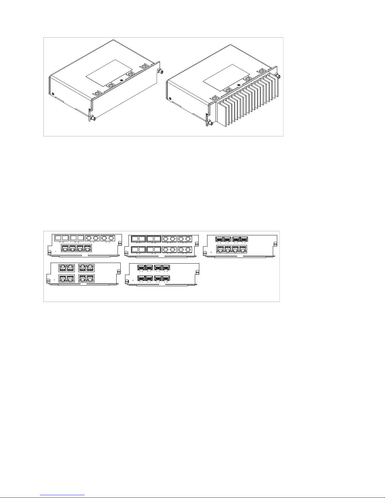
1.3 Device views
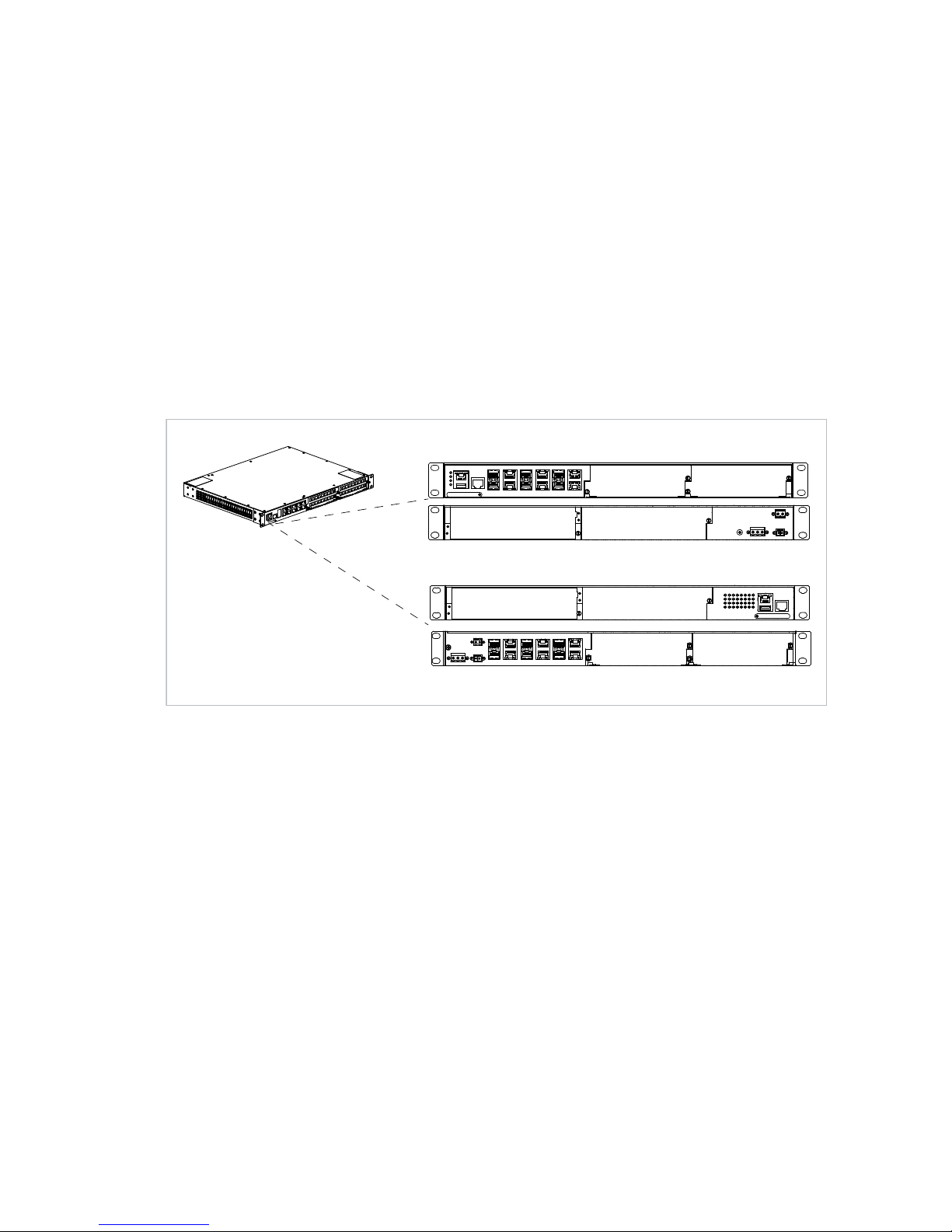
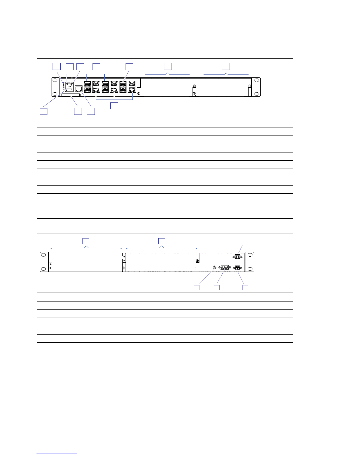
1.3.1 GRS1042
Front view - 6TX/6FX
1 LED display elements for device status
2 Display elements for power supply unit status
3 V.24 interface
4 SFP slot for 1/2.5 Gbit/s F/O connections
5 SFP slot for 100/1000 Mbit/s F/O connections
6 ... 7 Cover panels for media module slot
8 RJ45 socket for 10/100/1000 Mbit/s Twisted Pair connections
9 Out-of-band management port
10 Slot for the SD card
11 USB interface
Rear view - 6TX/6FX and 10TX/2FX
1 Cover panel for power supply unit slot 1
2 Cover panel for power supply unit slot 2
3 2-pin terminal block for the supply voltage, characteristic value L
4 Connection for the signal contact
5 3-pin terminal block for the supply voltage, characteristic value H
6 Grounding screw
7
6
1010
1111
4
8
2
3
5
1
9
3
1
2
4
5
6
Page 21
Installation GREYHOUND Switch
Release 01 04/2016
21
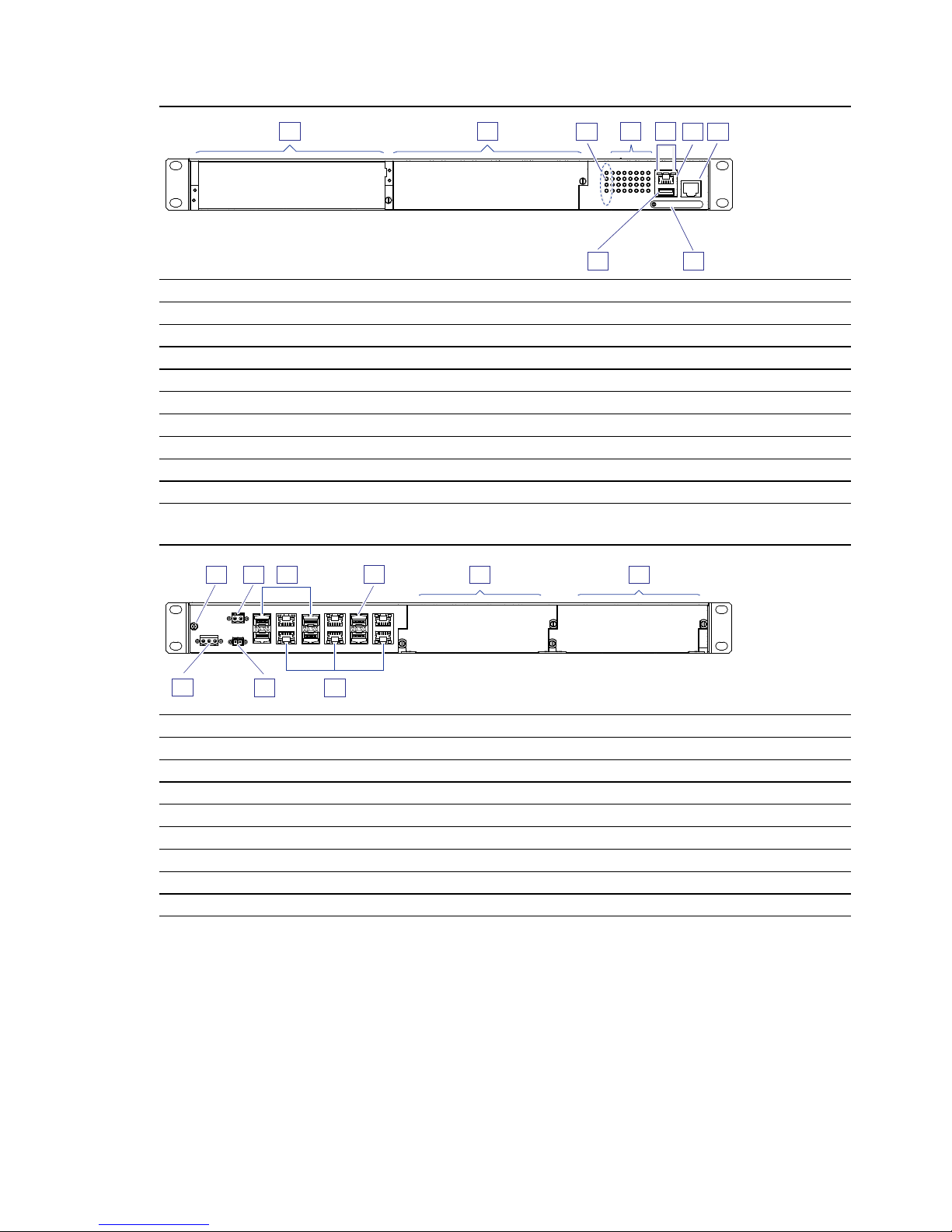
1.3.2 GRS1142
Front view - 6TX/6FX and 10TX/2FX
1 Cover panel for power supply unit slot 1
2 Cover panel for power supply unit slot 2
3 LED display elements for device status
4 LED display elements for port status
5 Display elements for power supply unit status
6 V.24 interface
7 Out-of-band management port
8 Slot for the SD card
9 USB interface
Rear view - 6TX/6FX
1 Grounding screw
2 2-pin terminal block for the supply voltage, characteristic value L
3 SFP slot for 1/2.5 Gbit/s F/O connections
4 SFP slot for 100/1000 Mbit/s F/O connections
5 ... 6 Cover panels for media module slot
7 RJ45 socket for 10/100/1000 Mbit/s Twisted Pair connections
8 Connection for the signal contact
9 3-pin terminal block for the supply voltage, characteristic value H
8
9
465
1
2
7
3
5
6
2
4
1
7
8
9
3
Page 22
22
Installation GREYHOUND Switch
Release 01 04/2016
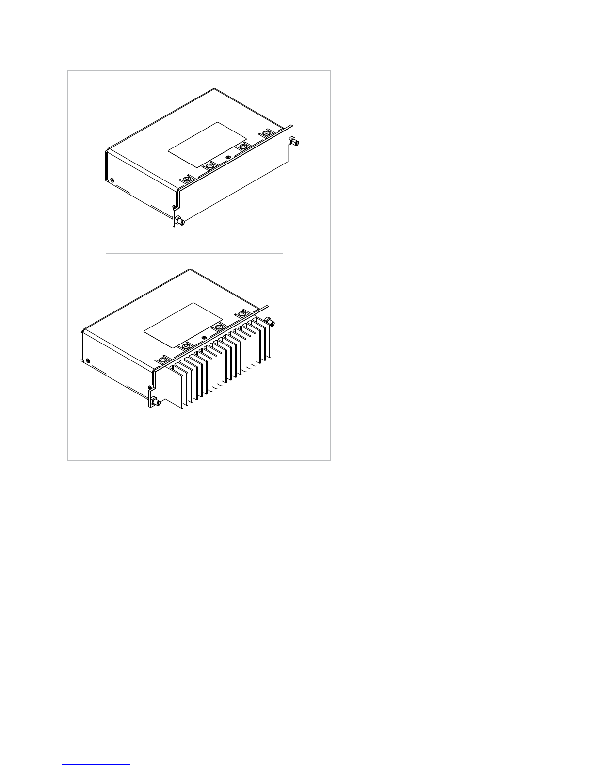
1.3.3 Power supply units
GPS1-C
GPS1-K
GPS3-P
Page 23
Installation GREYHOUND Switch
Release 01 04/2016
23
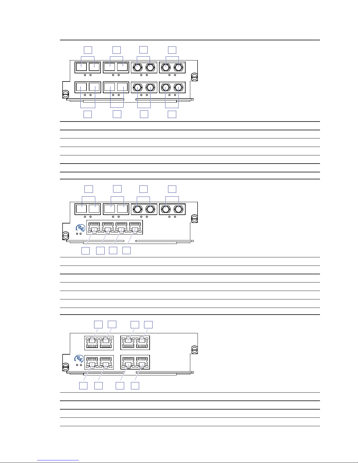
1.3.4 Media modules
GMM20-VVUUMMNN
Port Port description
1, 3 2 × DSC singlemode socket
5, 7 2 × ST singlemode socket
2, 4 2 × DSC multimode socket
6, 8 2 × ST multimode socket
GMM30-MMNNTTTT / GMM32-MMNNTTTT
Port Port description
1, 3 2 × DSC multimode socket
5, 7 2 × ST multimode socket
2, 4 2 × RJ45 socket
6, 8 2 × RJ45 socket
GMM40-TTTTTTTT / GMM42-TTTTTTTT
Port Port description
1, 3 2 × RJ45 socket
5, 7 2 × RJ45 socket
1
2
4 6
8
3
5
7
6
4
2
8
1
3
5
7
7
5
3
1
6
4
2
8
Page 24

24
Installation GREYHOUND Switch
Release 01 04/2016
2, 4 2 × RJ45 socket
6, 8 2 × RJ45 socket
GMM40-OOOOOOOO
Port Port description
1, 3 2 × SFP slot
5, 7 2 × SFP slot
2, 4 2 × SFP slot
6, 8 2 × SFP slot
GMM40-OOOOTTTT / GMM42-OOOOTTTT
Port Port description
1, 3 2 × SFP slot
5, 7 2 × SFP slot
2, 4 2 × RJ45 socket
6, 8 2 × RJ45 socket
7
5
3
1
6
4
2
8
6
4
2
8
7
5
3
1
Page 25

Installation GREYHOUND Switch
Release 01 04/2016
25
1.4 Power supply
You have the following options to supply your device with voltage:
via 2-pin terminal blocks
Device variants with characteristic value LL
via 3-pin terminal blocks
Device variants with characteristic value HH
via one 2-pin and one 3-pin terminal block
Device variants with characteristic value HL
You will find information on connecting the supply voltage here:
“Connecting the terminal blocks” on page 46.
GRS1042
GRS1142
GRS1042
GRS1142
GRS1042
GRS1142
Page 26

26
Installation GREYHOUND Switch
Release 01 04/2016
1.5 Signal contact
Figure 1: Signal contact: 2-pin terminal block with screw locking
The signal contact is a potential-free relay contact.
The device allows you to perform remote diagnosis via the signal contact. In
the process, the device signals events such as a line interruption. When an
event occurs, the device opens the relay contact and interrupts the closed
circuit. The management setting specifies which events switch a contact.
You can also use the management to switch the signal contact manually and
thus control external devices.
GRS1042
GRS1142
Page 27

Installation GREYHOUND Switch
Release 01 04/2016
27
1.6 Ethernet ports
You can connect end devices and other segments to the device and media
module ports using twisted pair cables or optical fibers (F/O).
1.6.1 1/2.5 Gbit/s F/O port
The port allows you to connect network components according to the IEEE
802.3 1000BASE-SX/1000BASE-LX standard.
The port allows you to connect network components according to
IEEE P802.3bz 2.5 Gbit/s.
This port supports:
Full duplex mode
Delivery state:
1/2.5 Gbit/s full duplex when using a Gigabit Ethernet SFP transceiver
1.6.2 100/1000 Mbit/s F/O port
This port is an SFP slot.
The 100/1000 Mbit/s F/O port offers you the ability to connect network
components according to the IEEE 802.3 100BASE-FX/1000BASESX/1000BASE-LX standard.
This port supports:
1000 Mbit/s full duplex
100 Mbit/s half-duplex mode, 100 Mbit/s full duplex mode
State on delivery:
100 Mbit/s full duplex when using a Fast Ethernet SFP transceiver
1000 Mbit/s full duplex when using a Gigabit Ethernet SFP transceiver
1.6.3 100 Mbit/s F/O port
This port is an SFP slot or an ST or DSC socket.
The 100 Mbit/s F/O port offers you the ability to connect network components
according to the IEEE 802.3 100BASE-FX standard.
This port supports:
100 Mbit/s half-duplex mode, 100 Mbit/s full duplex mode
Default setting: Full duplex
Applies to device variants with DSC ports or ST ports:
When connecting the data cables, note the sending and receiving directions.
Sending direction
Receiving direction
Page 28

28
Installation GREYHOUND Switch
Release 01 04/2016
1.6.4 10/100/1000 Mbit/s twisted pair port
This port is an RJ45 socket.
The 10/100/1000 Mbit/s twisted pair port offers you the ability to connect
network components according to the IEEE 802.3 10BASE-T/100BASETX/1000BASE-T standard.
This port supports:
Autonegotiation
Autopolarity
Autocrossing (if autonegotiation is activated)
1000 Mbit/s full duplex
100 Mbit/s half-duplex mode, 100 Mbit/s full duplex mode
10 Mbit/s half-duplex mode, 10 Mbit/s full duplex mode
Delivery state: Autonegotiation activated
You will find information on the pin assignment in a separate overview.
See “Pin assignments” on page 29.
1.6.5 Support of PoE(+)
The 10/100/1000 Mbit/s twisted pair port allows you to connect network
components according to the IEEE 802.3 10BASE-T/100BASETX/1000BASE-T and IEEE 802.3af/at standards.
The PoE power is supplied via the wire pairs transmitting the signal (phantom
voltage).
Maximum power available to a media module:
124 W
Page 29
Installation GREYHOUND Switch
Release 01 04/2016
29
1.6.6 Out-of-band management port
This port is an RJ45 socket.
The port allows you to connect network components according to the
IEEE 802.3 10BASE-T/100BASE-TX standard.
This port supports:
Autonegotiation
100 Mbit/s half duplex, 100 Mbit/s full duplex,10 Mbit/s half duplex,
10 Mbit/s full duplex
The port allows you to manage the device and upload configurations via the
following protocols:
SNMP
SSH
Telnet
FTP
SCP
HTTP/HTTPS
For more information see the Command Line Interface reference manual.
You can download the manual on the Internet at the Hirschmann product
pages www.hirschmann.com.
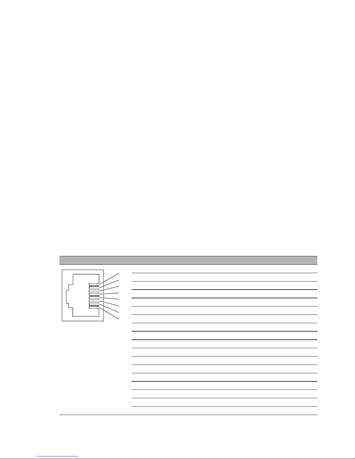
1.7 Pin assignments
RJ45 Pin 10/100 Mbit/s 1000 Mbit/s PoE
MDI mode
1 TX+ BI_DA+ Positive V
PSE
2TX− BI_DA− Positive V
PSE
3 RX+ BI_DB+ Negative V
PSE
4— BI_DC+ —
5— BI_DC− —
6RX− BI_DB− Negative V
PSE
7— BI_DD+ —
8— BI_DD− —
MDI-X mode
1 RX+ BI_DB+ Negative V
PSE
2RX− BI_DB− Negative V
PSE
3 TX+ BI_DA+ Positive V
PSE
4— BI_DD+ —
5— BI_DD− —
6TX− BI_DA− Positive V
PSE
7— BI_DC+ —
8— BI_DC− —
1
2
3
4
5
6
7
8
Page 30

30
Installation GREYHOUND Switch
Release 01 04/2016
1.8 Display elements
After the working voltage is set up, the software starts and initializes itself.
Afterwards, the device performs a self-test. During this process, various
LEDs light up.
1.8.1 Device state
These LEDs provide information about conditions which affect the operation
of the whole device.
LED Display Color Activity Meaning
Status Device Status — None Device is starting and/or is not ready for
operation
Green Lights up Device is ready for operation.
Characteristics can be configured
Red Lights up Device is ready for operation.
Device has detected at least one error in
the monitoring results
Flashes 1 time
a period
The boot parameters used when the
device has been started differ from the
boot parameters saved.
Start the device again.
flashes 4 times
a period
Device has detected a multiple IP address
RM Ring Manager — None No redundancy configured
Green Lights up Redundancy exists
Flashes 1 time
a period
Device is reporting an incorrect
configuration of the RM function
Yellow Lights up No redundancy exists
V.24
MGMT
P1
P2
USB
GRS1142
GRS1042
MGMT
P1
V.24
USB
P2
P1
P2
V.24
Page 31

Installation GREYHOUND Switch
Release 01 04/2016
31
ACA Storage medium
ACA22
ACA31
— None ACA storage medium not connected
Green Lights up ACA storage medium connected
Flashes 3
times a period
Device writes to/reads from the storage
medium
Yellow Lights up ACA storage medium inoperative
P Supply voltage — None Supply voltage is too low
Yellow Lights up Device variants with redundant power
supply:
Supply voltage 1 or 2 is on
flashes 4 times
a period
Software update is running. Maintain
the power supply.
Green Lights up Device variants with redundant power
supply:
Supply voltages 1 and 2 are on
Device variants with single power supply:
Supply voltage is on
P1 Supply voltage — None At least one of the following cases
applies:
Power supply unit is not connected
to slot P1.
There is no external supply voltage or
it is too low.
No internal supply voltage.
Green Lights up
Power supply unit is connected to
slot P1.
Boot procedure started
Valid supply voltage connected.
P2 Supply voltage — None At least one of the following cases
applies:
Power supply unit is not connected
to slot P2.
There is no external supply voltage or
it is too low.
No internal supply voltage.
Green Lights up
Power supply unit is connected
to slot P2.
Boot procedure started
Valid supply voltage connected.
LED Display Color Activity Meaning
Page 32

32
Installation GREYHOUND Switch
Release 01 04/2016
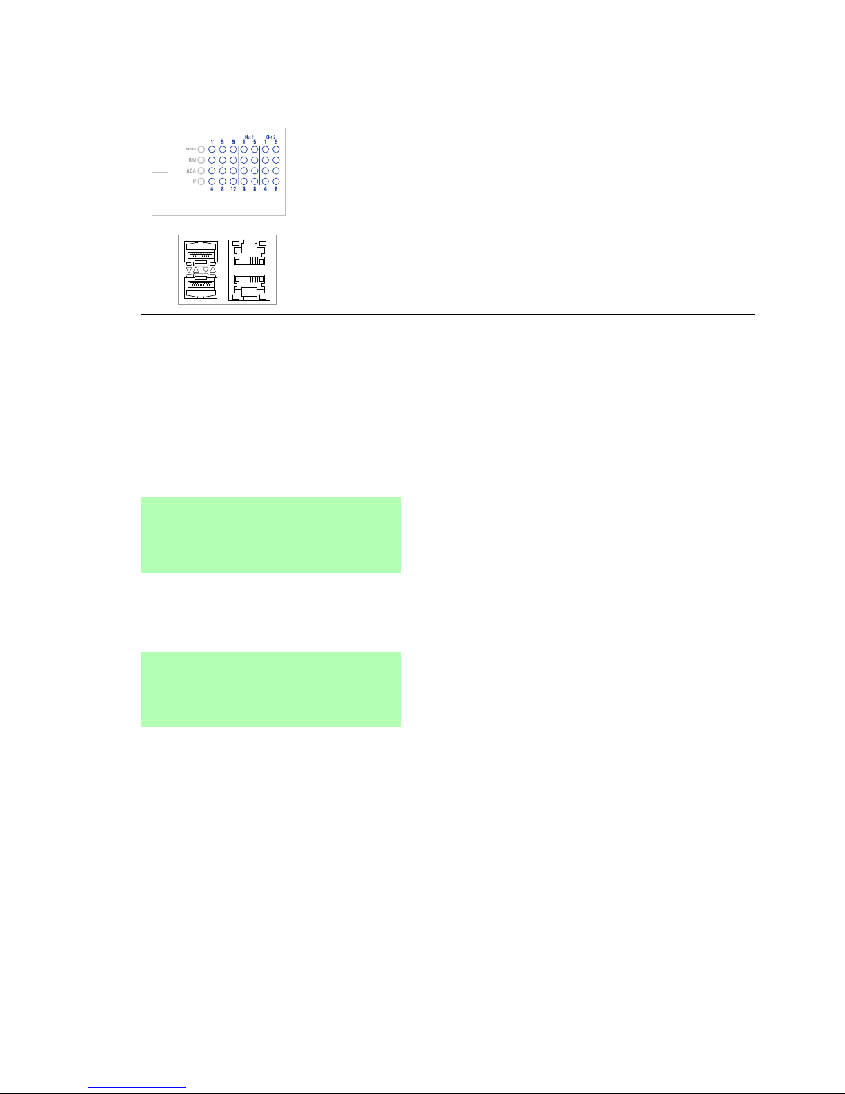
1.8.2 Port state
These LEDs provide port-related information.
LED Display Color Activity Meaning
L/D Link state/
data traffic
— None Device detects an invalid or missing
link
Green Lights up Device detects a valid link
Flashes 1 time a
period
Port is switched to stand-by
Flashes 3 times a
period
Port is switched off
Yellow Flashing alternately Device is transmitting and/or
receiving data
Lights up Device detects a non-supported SFP
transceiver or a non-supported data
rate
Flashes 1 time a
period
Device detects at least one
unauthorized MAC address (Port
Security Violation) and sends a trap.
Flashes 3 times a
period
The device deactivates the relevant
port (auto-deactivation).
L/D
GRS1042
GRS1142
GRS1142
L/D
LLD
D
V.24
MGMT
P1
P2
USB
MGMT
P1
P2
V.24
GRS1142
GRS1042
MGMT
L
D
444
1115
5
59
98812
Slot 1
Slot 2
Page 33
Installation GREYHOUND Switch
Release 01 04/2016
33
Switching LEDs
With device variants GRS 1142 the port status is displayed on the service
panel by default. You have the option of changing between the LED
displays using the command line interface (CLI). You require
administrator rights for this.
To change to the LED display on the port panel, execute the following
commands in the CLI:
To change to the LED display on the service panel, execute the following
commands in the CLI:
LED display Position on the device
Service panel Only device variants
GRS 1142
Port panel GRS 1042 and 1142
enable Change to the privileged EXEC mode.
configure Change to the configuration mode.
system port-led-mode
portpanel
Umschalten LED-Anzeige von Service-Panel auf
Port-Panel des Gerätes.
enable Change to the privileged EXEC mode.
configure Change to the configuration mode.
system port-led-mode
servicepanel
Umschalten LED-Anzeige von Port-Panel auf
Service-Panel.
Page 34

34
Installation GREYHOUND Switch
Release 01 04/2016
1.8.3 Media module status
GMM20/GMM30/GMM40
LED Display Color Activity Meaning
Power Supply
voltage
— None Media module is inoperative
Green Lights up Voltage supply to the media module is
on
L/D Link state/
data traffic
— None Device detects an invalid or missing link
Green Lights up Device detects a valid link
Flashes
1 time a
period
Port is switched to stand-by
Flashes
3 times a
period
Port is switched off
Yellow Lights up Device detects a non-supported SFP
transceiver or a non-supported data
rate
Flashing Device is transmitting and/or receiving
data
Flashes
1 time a
period
Device detects at least one
unauthorized MAC address
(Port Security Violation)
Power
Power
Power
Power
L
L
L
L
D
D
D
D
D
D
Power
L
L
Page 35

Installation GREYHOUND Switch
Release 01 04/2016
35
GMM32/GMM42
LED Display Color Activity Meaning
Power Supply voltage — None Media module is inoperative
Green Lights up Voltage supply to the media module is on
Voltage supply to the PoE port is on
Yellow Lights up PoE voltage is missing or is too low
L/D Link state/
data traffic
— None Device detects an invalid or missing link
Green Lights up Device detects a valid link
Flashes
1 time a
period
Port is switched to stand-by
Flashes
3 times a
period
Port is switched off
Yellow Lights up Device detects a non-supported SFP
transceiver or a non-supported data rate
Flashing Device is transmitting and/or receiving
data
Flashes
1 time a
period
Device detects at least one unauthorized
MAC address (Port Security Violation)
PoE PoE status Green Lights up Power device is supplied with PoE voltage
Yellow Flashes
1 time a
period
Output budget has been exceeded
Device has detected a connected
powered device
Flashes
3 times a
period
PoE administrator status deactivated
Power
Power
Power
Power
PoE
LD
LD
Power
PoE
L
D
LD
PoE
PoE
Power
LD
LD
Page 36

36
Installation GREYHOUND Switch
Release 01 04/2016
1.9 Management interfaces
1.9.1 V.24 interface (external management)
A serial interface is provided on the RJ45 socket (V.24 interface) for the local
connection of an external management station (VT100 terminal or PC with
corresponding terminal emulation). This enables you to set up a connection
to the Command Line Interface (CLI) and to the system monitor.
The socket housing is electrically connected to the front panel of the device.
The V.24 interface is electrically insulated from the supply voltage.
VT 100 terminal settings
Speed 9600 Baud
Data 8 bit
Stopbit 1 bit
Handshake off
Parity none
Figure Pin
assignment
Function
1—
2—
3TxD
4GND
5—
6RxD
7—
8—
Table 2: Pin assignment of the V.24 interface
GRS1142
GRS1042
1
2
3
4
5
6
7
8
Page 37
Installation GREYHOUND Switch
Release 01 04/2016
37
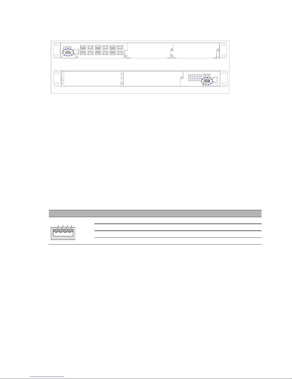
1.9.2 USB interface
The USB interface allows you to connect the AutoConfiguration Adapter
ACA22 storage medium. This is used for saving/loading the configuration
data and diagnostic information, and for loading the software.
See “Accessories” on page 71.
On the front of the device there is an LED display that informs you about the
status of the interface.
The USB interface has the following properties:
Supplies current of max. 500 mA
Voltage not potential-separated
Connectors: type A
Supports the USB master mode
Supports USB 2.0
Figure Pin Operation
1 VCC (VBus)
2 − Data
3 + Data
4 Ground (GND)
Table 3: Pin assignment of the USB interface
GRS1142
GRS1042
1
2
4
3
Page 38

38
Installation GREYHOUND Switch
Release 01 04/2016
1.9.3 SD card interface
Prerequisite:
Only use Hirschmann SD cards.
See “Accessories” on page 71.
The SD card interface allows you to connect the AutoConfiguration Adapter
ACA31 storage medium. This is used for saving/loading the configuration
data and diagnostic information, and for loading the software.
On the front of the device there is an LED display that informs you about the
status of the interface.
GRS1142
GRS1042
Page 39

Installation GREYHOUND Switch
Release 01 04/2016
39
2Installation
The devices have been developed for practical application in a harsh
industrial environment.
On delivery, the device is ready for operation.
Perform the following steps to install and configure the device:
Checking the package contents
Installing the SD card (optional)
Mounting the cover panel and the power supply unit (optional)
Mounting a media module (optional)
Installing and grounding the device
Connecting the terminal blocks
Operating the device
Installing an SFP transceiver (optional)
Connecting data cables
Filling out the inscription label
2.1 Checking the package contents
Check whether the package includes all items named in the section
“Scope of delivery” on page 70.
Check the individual parts for transport damage.
2.2 Installing the SD card (optional)
Prerequisite:
Only use the AutoConfiguration Adapter ACA31 storage medium.
See “Accessories” on page 71.
Proceed as follows:
Deactivate the write protection on the SD card by pushing the write-
protect lock towards the middle of the card.
Push the SD card into the slot with the beveled corner on the right side.
Page 40

40
Installation GREYHOUND Switch
Release 01 04/2016
2.3 Mounting the cover panel and the power
supply unit (optional)
2.3.1 Mounting the cover panel
Prerequisite:
To comply with the EMC requirements, close each of the free, open slots with
a cover panel, which you obtain as accessories.
See “Order number” on page 70.
Proceed as follows:
Place the cover panel over the power supply unit or media module slot of
the device.
Fasten the cover panel to the device by tightening the 2 screws.
2.3.2 Mounting the power supply unit
Hirschmann supplies the power supply units in a ready-to-operate state. The
power supply units are hot-swap-capable. You have the option of mounting
the power supply units while the device is operating.
Proceed as follows:
Remove the cover panel (if mounted) from the power supply unit slot on
the device.
Insert the power supply unit straight into the slot.
Fasten the power supply unit to the device by tightening the 2 screws.
The tightening torque is 4.4 lb-in (0.5 Nm).
2
1
3
Page 41

Installation GREYHOUND Switch
Release 01 04/2016
41
2.4 Mounting a media module (optional)
Hirschmann supplies the media modules in a ready-to-operate state. By
using a media module, you obtain up to 8 additional Fast and/or Gigabit
Ethernet ports. The media modules are hot-swap-capable. You have the
option of mounting the media modules while the device is operating.
Proceed as follows:
Remove the cover panel from the media module slot on the basic device.
Open the lock of the media module by pressing the locking lever outwards
(step 1).
Insert the media module straight into the media module slot (step 2).
Close the lock of the media module by pressing the locking lever inwards
(step 3).
Fasten the media module with the screws in the front panel of the basic
device.
The tightening torque is 4.4 lb-in (0.5 Nm).
1
2
3
Page 42
42
Installation GREYHOUND Switch
Release 01 04/2016
2.5 Installing and grounding the device
You have the following options for mounting your device:
Mounting in a switch cabinet
Mounting on a vertical flat surface
WARNING
ELECTRIC SHOCK
Install this device solely in a switch cabinet or in an operating site with
restricted access, to which maintenance staff have exclusive access.
Failure to follow these instructions can result in death, serious injury,
or equipment damage.
CAUTION
OVERHEATING OF THE DEVICE
When installing the device, ensure that the ventilation slots are not covered.
Failure to follow these instructions can result in injury or equipment
damage.
Page 43

Installation GREYHOUND Switch
Release 01 04/2016
43
Mounting in a switch cabinet
Note: When operating the device in an environment with continuous
vibration loads of greater than 0.7 g, you must additionally fasten the
device to the switch cabinet using 2 holding brackets on the front and
back of the device.
You obtain the additional brackets as accessories.
See “Accessories” on page 71.
Prerequisites:
Install the device in the 19" switch cabinet using sliding or mounting
rails.
This provides a more stable position of your device in environments
subject to vibration.
For more information on sliding/mounting rails and how to install them,
please contact your switch cabinet manufacturer.
The devices are designed to be mounted in a 19" switch cabinet.
In the delivery state, there are 2 pre-mounted holding brackets on the
sides of the device.
Verify that there is sufficient ventilation. If required, install a fan to keep
the device from overheating.
Measure the depth of the 19" cabinet so that all the lines to be
connected can be fed in easily.
Proceed as follows:
Assemble the sliding or mounting rails in the 19" switch cabinet as
specified by the manufacturer.
Position the device on the rails in the switch cabinet.
Fasten the device by screwing the brackets to the switch cabinet.
The tightening torque is 4.4 lb-in (0.5 Nm).
Page 44
44
Installation GREYHOUND Switch
Release 01 04/2016
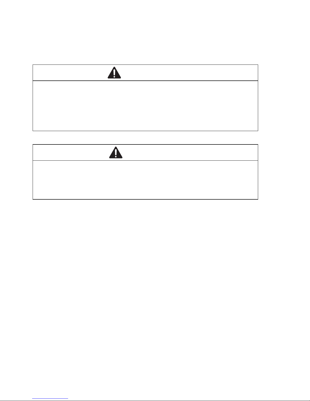
Mounting on a vertical flat surface
Proceed as follows:
Use the pre-mounted brackets as shown below.
Additionally attach 2 brackets to the back of the device.
You obtain the additional brackets as accessories.
See “Accessories” on page 71.
Fasten the device by screwing the brackets to the wall.
The tightening torque is 4.4 lb-in (0.5 Nm).
WARNING
FIRE HAZARD
Install the device in a fire protected shell if you are mounting it vertically.
Failure to follow these instructions can result in death, serious injury,
or equipment damage.
Page 45

Installation GREYHOUND Switch
Release 01 04/2016
45
Grounding the device
The device variants have a connection for protective grounding.
Applies to device variants featuring supply voltage with characteristic
value H:
The device is grounded via the ground screw and also via the power
supply socket.
Proceed as follows:
Ground the device via the ground screw.
Page 46

46
Installation GREYHOUND Switch
Release 01 04/2016
2.6 Connecting the terminal blocks
2.6.1 Supply voltage
You have the option of supplying the supply voltage redundantly, without
load distribution.
Note: The supply voltage is connected to the device casing through
protective elements exclusively.
Note: The supply voltage for the power supply units is provided at terminal
blocks P1 and P2 for the corresponding slots P1 and P2.
For every supply voltage to be connected, perform the following steps:
Remove the power connector from the device.
Connect the wires according to the pin assignment on the device with the
clamps.
See Supply voltage with characteristic value LL.
See Supply voltage with characteristic value HH.
See Supply voltage with characteristic value HL.
Fasten the wires connected by tightening the terminal screws.
WARNING
ELECTRIC SHOCK
Connect only a supply voltage that corresponds to the type plate of your
device.
Never insert sharp objects (small screwdrivers, wires, etc.) into the
connection terminals for electric conductors, and do not touch the terminals.
Failure to follow these instructions can result in death, serious injury,
or equipment damage.
Page 47

Installation GREYHOUND Switch
Release 01 04/2016
47
Supply voltage with characteristic value LL
Supply voltage with characteristic value HH
X
zRELAY
P2
-
+
P1
-
+
GRS1142
GRS1042
P1
P2
P1
GRS1042
P2
GRS1142
P1
P2
Page 48

48
Installation GREYHOUND Switch
Release 01 04/2016
Supply voltage with characteristic value HL
Type of the voltages
that can be
connected
Specification of the supply
voltage
Connections
DC voltage Rated voltage range DC
24 V ... 48 V
48 V... 54 V
+ Plus terminal of the supply voltage
− Minus terminal of the supply
voltage
Table 4: Supply voltage with characteristic value LL: type and specification of the
supply voltage, connections
Type of the voltages
that can be connected
Specification of the supply
voltage
Connections
DC voltage Rated voltage range DC
60 V ... 250 V
+/L
−/N
Plus terminal of the supply
voltage
Minus terminal of the supply
voltage
Protective conductor
AC voltage Rated voltage range AC
110 V ... 240 V, 50 Hz ... 60 Hz
+/L
−/N
Outer conductor
Neutral conductor
Protective conductor
Table 5: Supply voltage with characteristic value HH: type and specification of the
supply voltage, connections
X
RELAY
P2
P1
z
P1 P2
GRS1142
GRS1042
-
+
Page 49

Installation GREYHOUND Switch
Release 01 04/2016
49
2.6.2 Signal contact
Figure 2: Signal contact: 2-pin terminal block with screw locking
Connect the signal contact wires with the connectors of the terminal block.
Fasten the wires connected by tightening the terminal screws.
GRS1042
GRS1142
Page 50
50
Installation GREYHOUND Switch
Release 01 04/2016
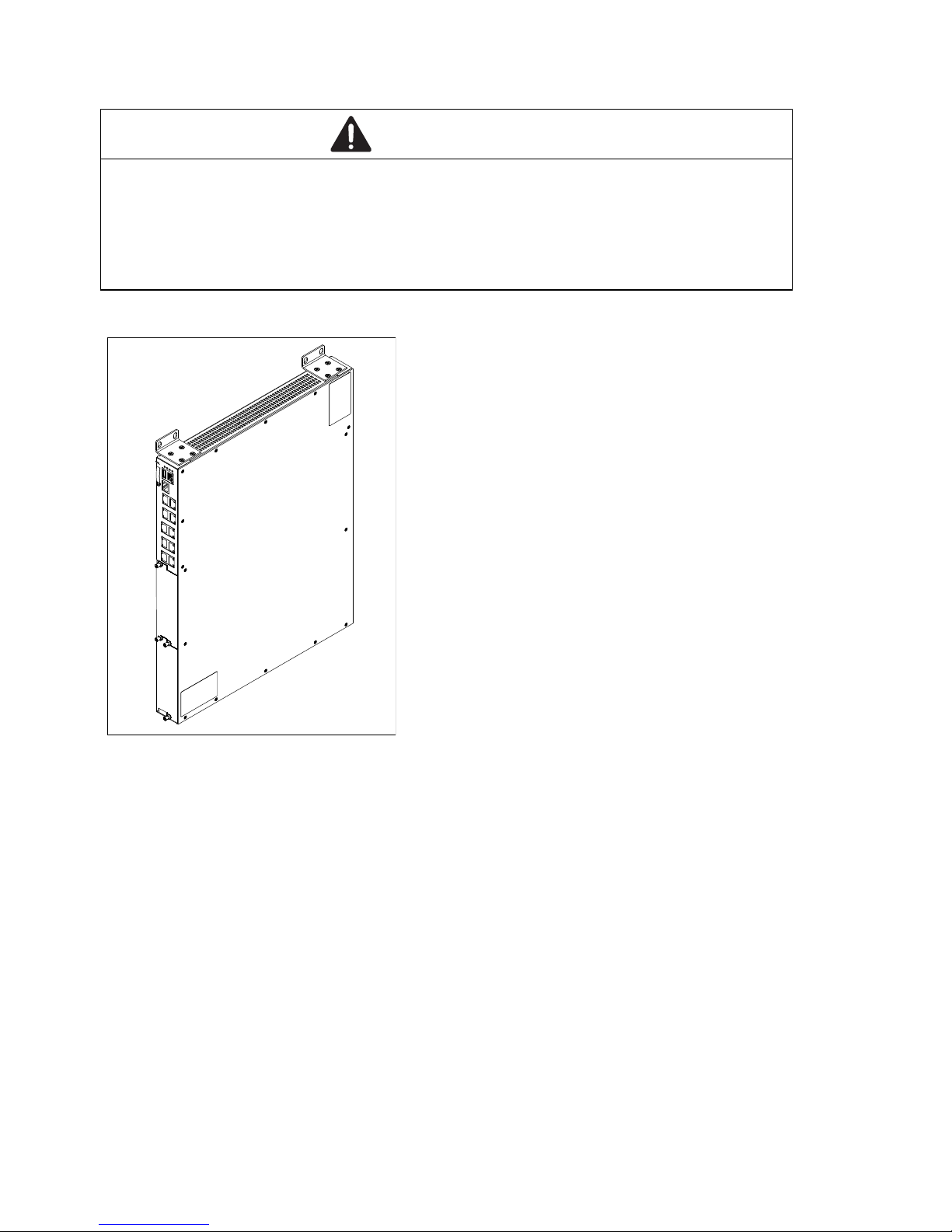
2.7 Installing an SFP transceiver (optional)
Prerequisite:
Only use Hirschmann SFP transceivers.
See “Accessories” on page 71.
Proceed as follows:
Remove the protection cap from the SFP transceiver.
Push the SFP transceiver with the lock closed into the slot until it
latches in.
Page 51

Installation GREYHOUND Switch
Release 01 04/2016
51
2.8 Operating the device
Relevant for North America:
The torque for tightening the supply voltage terminal block on the device
is 4.5 lb-in (0.51 Nm).
The torque for tightening the terminal block for the signal contact on the
device is 3 lb-in (0.34 Nm).
Proceed as follows:
Use screws to secure the connectors to the device.
Enable the supply voltage.
2.9 Connecting data cables
Note the following general recommendations for data cable connections in
environments with high electrical interference levels:
Keep the length of the data cables as short as possible.
Use optical data cables for the data transmission between the buildings.
When using copper cables, provide a sufficient separation between the
power supply cables and the data cables. Ideally, install the cables in
separate cable channels.
Verify that power supply cables and data cables do not run parallel over
longer distances, and that ideally they are installed in separate cable
channels. If reducing the inductive coupling is necessary, verify that the
power supply cables and data cables cross at a 90° angle.
Use shielded cables (SF/UTP cables as per ISO/IEC 11801:2002).
Connect the data cables according to your requirements.
For further information see “Device name and product code” on page 15.
2.10 Filling out the inscription label
The information field for the MAC address on the front of the device helps you
identify your device.
Page 52

52
Installation GREYHOUND Switch
Release 01 04/2016
3 Making basic settings
Note: Two or more devices configured with the same IP address can cause
unpredictable operation of your network.
Install and maintain a process that assigns a unique IP address to every
device in the network.
The IP parameters must be entered when the device is installed for the first
time. The device provides 6 options for configuring the IP addresses:
Entry via V.24 connection
Entry using the HiDiscovery protocol via the HiDiscovery or
Industrial HiVision application
a
Configuration via BOOTP
a
Configuration via DHCP
a
Configuration via DHCP Option 82
a
AutoConfiguration Adapter
Default settings
IP address: The device looks for the IP address using DHCP
a
Password for management:
Login: user; password: public (read only)
Login: admin; password: private (read and write)
Parameters that can be set via the management are set to pre-defined
values in accordance with the MIB
V.24 data rate: 9,600 Baud
Ring redundancy: disabled
Ethernet ports: link status is not evaluated (signal contact)
Optical 100 Mbit/s ports: 100 Mbit/s, full duplex
All other ports: autonegotiation
Out-of-band management port:
Default IP address: 192.168.1.1 / 255.255.255.0
a. Out-of-band management port excluded
Page 53

Installation GREYHOUND Switch
Release 01 04/2016
53
4 Monitoring the ambient air temperature
Operate the device below the specified maximum ambient air temperature
exclusively.
See “General technical data” on page 58.
The ambient air temperature is the temperature of the air at a distance of 2 in
(5 cm) from the device. It depends on the installation conditions of the device,
e.g. the distance from other devices or other objects, and the output of
neighboring devices.
Page 54

54
Installation GREYHOUND Switch
Release 01 04/2016
5 Maintenance and service
When designing this device, Hirschmann largely avoided using high-wear
parts. The parts subject to wear and tear are dimensioned to last longer
than the lifetime of the product when it is operated normally. Operate this
device according to the specifications.
Relays are subject to natural wear. This wear depends on the frequency
of the switching operations. Check the resistance of the closed relay
contacts and the switching function depending on the frequency of the
switching operations.
Hirschmann is continually working on improving and developing their
software. Check regularly whether there is an updated version of the
software that provides you with additional benefits. You find information
and software downloads on the Hirschmann product pages on the
Internet (www.hirschmann.com).
Depending on the degree of pollution in the operating environment, check
at regular intervals that the ventilation slots in the device are not
obstructed.
You will find information about the complaints and returns procedures on the
Internet under
http://www.beldensolutions.com/en/Service/Repairs/index.phtml .
Page 55

Installation GREYHOUND Switch
Release 01 04/2016
55
6Disassembly
6.1 Removing a power supply unit
Proceed as follows:
Remove the screws on the front panel of the power supply unit.
Pull the power supply unit out of the slot.
Close the power supply unit slot on the basic device using a cover panel.
Fasten the cover panel using the 2 screws on the basic device.
The tightening torque is 4.4 lb-in (0.5 Nm).
2
1
3
Page 56

56
Installation GREYHOUND Switch
Release 01 04/2016
6.2 Removing a media module
Proceed as follows:
Loosen the screws in the front panel of the media module.
Open the lock of the media module by pressing the locking lever outwards
(steps 1 and 2).
Pull the media module out of the slot (step 3).
Close the media module slot on the basic device using a cover panel.
Fasten the cover panel using the 2 screws on the basic device.
The tightening torque is 4.4 lb-in (0.5 Nm).
6.3 Removing an SFP transceiver
Proceed as follows:
Pull the SFP transceiver out of the slot by means of the opened lock.
Close the SFP transceiver with the protective cap.
1
2
3
1
2
Page 57

Installation GREYHOUND Switch
Release 01 04/2016
57
6.4 Removing the device
Proceed as follows:
Disconnect the data cables.
Disable the supply voltage.
Disconnect the terminal blocks.
Disconnect the grounding.
To detach the device from the switch cabinet or the wall, remove the
screws from the brackets on the device.
WARNING
ELECTRIC SHOCK
Disconnect the grounding only after disconnecting all other cables.
Failure to follow these instructions can result in death, serious injury,
or equipment damage.
Page 58

58
Installation GREYHOUND Switch
Release 01 04/2016
7 Technical data
7.1 General technical data
7.1.1 Basic device
Dimensions
W × H × D
See “Dimension drawings” on page 62.
Weight 7.93 lb (3.6 kg)
Power supply
Supply voltage
with characteristic
value L
Nominal voltage DC 24 V ... 48 V
48 V... 54 V
Back-up fuse for each voltage
input
Nominal rating:
Characteristic:
6.3 A
slow blow
Connection type 2-pin terminal block
Power supply
Supply voltage
with characteristic
value H
Nominal voltage AC 110 V ... 240 V, 50 Hz ... 60 Hz
Nominal voltage DC 60 V ... 250 V
Back-up fuse for each voltage
input
Nominal rating:
Characteristic:
2.5 A
slow blow
Connection type 3-pin terminal block
Signal contact Nominal value for AC I
max
=2A at U
max
=230V
Nominal value for DC I
max
=2A at U
max
=30V
I
max
=0.2 A at U
max
= 125 V
I
max
=0.1A at U
max
= 250 V
Climatic conditions
during operation
Ambient air temperature
a
Standard
up to 6560 FASL
(2000 m ü. NN)
over 6562 FASL
(2000 m)
+32 °F ... +140 °F
(0 °C ... +60 °C)
+32 °F to +122 °F
(0 °C ... +50 °C)
Extended
b ,c
up to 6560 FASL
(2000 m ü. NN)
over 6562 FASL
(2000 m)
−40 °F ... +158 °F
(−40 °C ... +70 °C)
−40 °F ... +140 °F
(−40 °C ... +60 °C)
Extended with
conformal coating
b,c
over 6562 FASL
(2000 m)
over 6562 FASL
(2000 m)
−40 °F ... +158 °F
(−40 °C ... +70 °C)
−40 °F ... +140 °F
(−40 °C ... +60 °C)
Humidity 5 % ... 95 % (non-condensing)
Air pressure minimum 700 hPa (+9842 ft; +3000 m)
maximum 1060 hPa (−1312 ft; −400 m)
Climatic conditions
during storage
Ambient temperature −40 °F ... +185 °F
(−40 °C ... +85 °C)
Humidity 5 % ... 95 % (non-condensing)
Air pressure minimum 700 hPa (+9842 ft; +3000 m)
maximum 1060 hPa (−1312 ft; −400 m)
Page 59

Installation GREYHOUND Switch
Release 01 04/2016
59
7.1.2 Power supply units
Pollution degree 2
Protection classes Laser protection Class 1 in compliance with IEC 60825-1
Degree of protection IP30
a. Temperature of the ambient air at a distance of 2 inches (5 cm) from the device
b. If you are using SFP modules without the “EEC” extension, an operating temperature range
of +32 °F to +140 °F (0 °C to +60 °C) applies for your device.
c. Applies to GRS device variants with the extended temperature range:
If more than 4 SFP transceivers are used, the maximum operating temperature is reduced
by 2 K per additional SFP transceiver.
Dimensions
W × H × D
See “Power supply units” on page 63.
Weight GPS1-C 21.16 oz (600 g)
GPS1-K 25.04 oz (710 g)
GPS3-P 26.46 oz (750 g)
Power supply unit
Characteristic value C
Nominal voltage DC 24 V ... 48 V
Voltage range DC incl.
maximum tolerances:
min. 16.8 V ... max. 60 V
Power loss buffer > 10 ms at 20.4 V DC
Overload current protection
at input
Non-replaceable fuse
Peak inrush current < 7A (1ms)
Current integral I
2
T0.4A
2
s
Power supply unit
Characteristic value K
Nominal voltage AC 110 V ... 240 V, 50 Hz ... 60 Hz
Nominal voltage DC 60 V ... 250 V
Voltage range AC incl.
maximum tolerances
88 V ... 276 V, 47 Hz ... 63 Hz
Voltage range DC incl.
maximum tolerances
48 V ... 288 V
Power loss buffer > 17 ms at 110 V AC
> 20 ms at 230 V AC
Overload current protection
at input
Non-replaceable fuse
Peak inrush current < 3A (1ms)
Current integral I
2
T0.3A
2
s
Crest factor < 1.8
Page 60

60
Installation GREYHOUND Switch
Release 01 04/2016
Power supply unit
Characteristic value P
The supply voltage inputs are designed for operation with safety extralow voltage. Connect only SELV circuits with voltage restrictions in line
with IEC/EN 60950-1 to the supply voltage connections.
Make sure that the connected supply voltage complies the
requirements of IEEE 802.3af or IEEE 802.3at:
For the use of type-1-powered devices (PoE):
Rated voltage DC: 48 V
Max. voltage range DC: 45 V ... 57 V
For the use of type-2-powered devices (PoE+):
Rated voltage DC: 54 V
Max. voltage range DC: 51 V ... 57 V
Max. PoE power In total: 185 W
Power loss buffer > 10 ms at 40.8 V DC
a
Overload current protection
at input
Non-replaceable fuse
Peak inrush current < 2.5A (1ms)
Current integral I
2
T0.3A
2
s
a. Only applies to the basic device, not to the connected powered devices.
Page 61

Installation GREYHOUND Switch
Release 01 04/2016
61
7.1.3 Media modules
Dimensions See “Dimension drawings” on page 62.
Weight of media
modules
GMM20-MMMMMMMM 16.72 oz (520 g)
additional 150 g for media modules with
temperature range characteristic value
T and E
GMM20-NNNNNNNN
GMM20-VVVVVVVV
GMM20-UUUUUUUU
GMM30-MMMMTTTT 19.4 oz (550 g)
GMM30-NNNNTTTT
GMM30-VVVVTTTT
GMM30-UUUUTTTT
GMM40-TTTTTTTT 17.28 oz (490 g)
GMM40-OOOOOOOO 22.93 oz (650 g)
GMM40-OOOOTTTT 19.05 oz (540 g)
GMM32-MMMMTTTT 19.75 oz (560 g)
GMM32-NNNNTTTT
GMM32-VVVVTTTT
GMM32-UUUUTTTT
GMM42-OOOOTTTT 19.4 oz (550 g)
GMM42-TTTTTTTT 17.99 oz (510 g)
Climatic conditions
during operation
Ambient temperature Devices with operating temperature
characteristic value S (standard):
+32 °F ... +140 °F (0 °C ... +60 °C)
a
a. Hirschmann recommends to use SFP transceivers with the "EEC" extension.
Devices with operating temperature
characteristic value E and T (extended)
−40 °F ... +158 °F (−40 °C ... +70 °C)
b
−40 °F ... +185 °F (−40 °C ... +85 °C)
for 16 hours (tested in accordance with
IEC 60068-2-2)
b. Use SFP transceivers with the “EEC” extension only, otherwise the standard temperature
range applies.
Humidity 5 % ... 95 %
(non-condensing)
Air pressure at least 600 hPa (+13123 ft; +4000 m)
maximum 1060 hPa (−1312 ft; −400 m)
Climatic conditions
during storage
Ambient temperature −40 °F ... +185 °F (−40 °C ... +85 °C)
Humidity 5 % ... 95 %
(non-condensing)
Air pressure at least 600 hPa (+13123 ft; +4000 m)
maximum 1060 hPa (−1312 ft; −400 m)
Pollution degree 2
Protection classes Laser protection Class 1 in compliance with IEC 60825-1
Page 62

62
Installation GREYHOUND Switch
Release 01 04/2016
7.2 Dimension drawings
7.2.1 Basic device
444
17
466
18
483
19
32
1
44
1.8
10
0.39
354
14
mm
inch
6,9
0.27
Page 63

Installation GREYHOUND Switch
Release 01 04/2016
63
7.2.2 Power supply units
167
6.6
173
mm
inch
6.8
42
1.65
109
4.3
167
6.6
173
6.8
42
8
0.3
1.65
109
4.3
141
5.5
Page 64

64
Installation GREYHOUND Switch
Release 01 04/2016
7.2.3 Media modules
130
5.1
115
4.5
140
5.5
4
0.1
37,5
1.5
41,5
1.6
129
5
135
5.3
mm
inch
Page 65

Installation GREYHOUND Switch
Release
01
04/2016
65
EMC and immunity
EMC interference
emission
Standard
applications
a
a. EN 61131-2, CE, FCC – applies to all devices
Merchant Navy
b
b. Merchant Navy – applies to devices with the approval codes U9, UT, UX, UY, VU
Railway
applications
(trackside)
c,d
c. EN 50121-4, EN 50155 – applies to devices with the approval codes VT, T9, TY, S9, SY
d. EN 50155 – applies to devices with the approval codes S9, SY
Substation
applications
e
e. EN 61850-3, IEEE 1613 – applies to devices with the certification codes V9, VY, VU, VT
Radiated emission
EN 55022 Class A Class A Class A Class A
GL Guidelines — EMC 1 — —
FCC 47 CFR Part 15 Class A Class A Class A Class A
EN 61000-6-4 Fulfilled Fulfilled Fulfilled Fulfilled
Conducted emission
EN 55022 DC supply connection Class A Class A Class A Class A
GL Guidelines DC supply connection — EMC 1 — —
FCC 47 CFR Part 15 DC supply connection Class A Class A Class A Class A
EN 61000-6-4 DC supply connection Fulfilled Fulfilled Fulfilled Fulfilled
EN 55022 Telecommunication connections Class A Class A Class A Class A
EN 61000-6-4 Telecommunication connections Fulfilled Fulfilled Fulfilled Fulfilled
EMC interference
immunity
Standard
applications
a
Merchant NavybRailway
applications
(trackside)
c
Substation
applications
d
Electrostatic discharge
EN 61000-4-2
IEEE C37.90.3
Contact discharge ± 4 kV ± 6 kV ± 6 kV ± 8 kV
EN 61000-4-2
IEEE C37.90.3
Air discharge ±8kV ±8kV ±8kV ±15kV
Electromagnetic field
Page 66

66
Installation GREYHOUND Switch
Release
01
04/2016
EN 61000-4-3 80 MHz ... 3000 MHz 10 V/m 10 V/m 20 V/m 10 V/m
IEEE 1613 80 MHz ... 1000 MHz — — — 35 V/m
Fast transients (burst)
EN 61000-4-4
IEEE C37.90.1
DC supply connection ± 2 kV ± 2 kV ± 2 kV ± 4 kV
EN 61000-4-4
IEEE C37.90.1
Data line ±4kV ±4kV ± 2kV ±4kV
Voltage surges - DC supply connection
EN 61000-4-5 line/ground ± 2 kV ± 2 kV ± 2 kV ± 2 kV
IEEE 1613 line/ground — — — ± 5 kV
EN 61000-4-5 line/line ± 1 kV ± 1 kV ± 1 kV ± 1 kV
Voltage surges - data line
EN 61000-4-5 line/ground ± 1 kV ± 1 kV ± 2 kV ± 2 kV
Conducted disturbances
EN 61000-4-6 150 kHz ... 80 MHz 10 V 10 V 10 V 10 V
EMC interference
immunity
Standard
applications
a
Merchant NavybRailway
applications
(trackside)
c
Substation
applications
d
Page 67

Installation GREYHOUND Switch
Release
01
04/2016
67
Damped vibration – DC supply connection
EN 61000-4-12
IEEE C37.90.1
line/ground — — — 2.5 kV
EN 61000-4-12
IEEE C37.90.1
line/line — — — 1 kV
Damped oscillation - data line
EN 61000-4-12
IEEE C37.90.1
line/ground — — — 2.5 kV
EN 61000-4-12 line/line — — — ± 1 kV
Pulse magnetic fields
EN 61000-4-9 — — 300 A/m —
a. EN 61131-2, CE, FCC – applies to all devices
b. Merchant Navy – applies to devices with the approval codes U9, UT, UX, UY, VU
c. EN 50121-4 – applies to devices with the approval codes VT, T9, TY, S9, SY
d. EN 61850-3, IEEE 1613 – applies to devices with the certification codes V9, VY, VU, VT
Stability Standard
applications
a
a. EN 61131-2, CE, FCC – applies to all devices
Merchant Navy
b
b. Merchant Navy – applies to devices with the approval codes U9, UT, UX, UY, VU
Railway applications
(trackside)
c
c. EN 50121-4 – applies to devices with the approval codes VT, T9, TY, S9, SY
Substation
applications
d
d. EN 61850-3, IEEE 1613 – applies to devices with the certification codes V9, VY, VU, VT
IEC 60068-2-6, test Fc Vibration 5 Hz ... 8.4 Hz with
0.14 in. (3.5 mm)
amplitude
2 Hz ... 13.2 Hz with
0.04 in. (1 mm)
amplitude
— 2 Hz ... 9 Hz with
0.12 in. (3 mm)
amplitude
8.4 Hz ... 150 Hz
with 1 g
—
13.2 Hz ... 200 Hz
with 0.7 g
—
—
—
9 Hz ... 200 Hz
with 1 g
200 Hz ... 500 Hz
with 1.5 g
IEC 60068-2-27, test Ea Shock 15 g at 11 ms — — 10 g at 11 ms
EMC interference
immunity
Standard
applications
a
Merchant NavybRailway
applications
(trackside)
c
Substation
applications
d
Page 68

68
Installation GREYHOUND Switch
Release 01 04/2016
Network range
Note: The line lengths specified for the transceivers apply for the
respective fiber data (fiber attenuation and BLP/dispersion).
Product
code
M-SFP-...
Wave
length
Fiber System
attenuatio
n
Example
for F/O
line
length
a
a. including 3 dB system reserve when compliance with the fiber data is observed
Fiber
attenuatio
n
BLPb/
dispersion
b. Using the bandwidth length product is inappropriate for expansion calculations.
-SX/LC... MM 850 nm 50/125 µm 0-7.5 dB 0-550 m 3.0 dB/km 400 MHz×km
-SX/LC... MM 850 nm 62.5/125 µm 0-7.5 dB 0-275 m 3.2 dB/km 200 MHz×km
-MX/LC MM 1310 nm 50/125 µm 0-8 dB 2 km
c
c. Distances of up to 3 km can be reached, 1000 MHz×km (1300 nm)
1.0 dB/km 500 MHz×km
-MX/LC MM 1310 nm 62.5/125 µm 0-8 dB 1 km 1.0 dB/km 500 MHz×km
-LX/LC... MM 1310 nm
d
d. With F/O adapter compliant with IEEE 802.3-2002 clause 38 (single-mode fiber offset-launch
mode conditioning patch cord)
50/125 µm 0-10.5 dB 0-550 m 1.0 dB/km 800 MHz×km
-LX/LC... MM 1310 nm
c
62.5/125 µm 0-10.5 dB 0-550 m 1.0 dB/km 500 MHz×km
-LX/LC... SM 1310 nm 9/125 µm 0-10.5 dB 0-20 km
e
e. Including 2.5 dB system reserve when compliance with the fiber data is observed
0.4 dB/km 3.5 ps/(nm×km)
-LX+/LC... SM 1310 nm 9/125 µm 5-20 dB 14-42 km 0.4 dB/km 3.5 ps/(nm×km)
-LH/LC... LH 1550 nm 9/125 µm 5-22 dB 23-80 km 0.25 dB/km 19 ps/(nm×km)
-LH+/LC LH 1550 nm 9/125 µm 15-30 dB 71-108 km 0.25 dB/km 19 ps/(nm×km)
-LH+/LC LH 1550 nm 9/125 µm 15-30 dB 71-128 km 0.21 dB/km
(typically)
19 ps/(nm×km)
Table 6: Fiber port 1000BASE-FX (SFP fiber optic Gigabit Ethernet Transceiver)
Product
code
M-SFPBIDI...
Wave
length
TX
Wave
length
RX
Fiber System
attenuat
ion
Example
for F/O
line
length
a
a. including 3 dB system reserve when compliance with the fiber data is observed
Fiber
attenuatio
n
Dispersion
Type A
LX/LC EEC
SM 1310 nm 1550 nm 9/125 µm 0-11 dB 0-20 km 0.4 dB/km 3.5
ps/(nm×km)
Type B
LX/LC EEC
SM 1550 nm 1310 nm 9/125 µm 0-11 dB 0-20 km 0.25 dB/km 19
ps/(nm×km)
Type A
LH/LC EEC
LH 1490 nm 1590 nm 9/125 µm 5-24 dB 23-80 km 0.25 dB/km 19
ps/(nm×km)
Type B
LH/LC EEC
LH 1590 nm 1490 nm 9/125 µm 5-24 dB 23-80 km 0.25 dB/km 19
ps/(nm×km)
Table 7: F/O port (bidirectional Gigabit Ethernet SFP Transceiver)
Page 69

Installation GREYHOUND Switch
Release 01 04/2016
69
Product
code
M-FASTSFP-...
Wave
length
Fiber System
attenuatio
n
Example
for F/O line
length
a
a. including 3 dB system reserve when compliance with the fiber data is observed
Fiber
attenuation
BLP/
dispersion
-MM/LC... MM 1310 nm 50/125 µm 0-8 dB 0-5 km 1.0 dB/km 800 MHz×km
-MM/LC... MM 1310 nm 62.5/125 µm 0-11 dB 0-4 km 1.0 dB/km 500 MHz×km
-SM/LC... SM 1310 nm 9/125 µm 0-13 dB 0-25 km 0.4 dB/km 3.5 ps/(nm×km)
-SM+/LC... SM 1310 nm 9/125 µm 10-29 dB 25-65 km 0.4 dB/km 3.5 ps/(nm×km)
-LH/LC... SM 1550 nm 9/125 µm 10-29 dB 47-104 km 0.25 dB/km 19 ps/(nm×km)
-LH/LC... SM 1550 nm 9/125 µm 10-29 dB 55-140 km 0.18 dB/km
b
b. with ultra-low-loss optical fiber
18 ps/(nm×km)
Table 8: Fiber port 100BASE-FX (SFP fiber optic Fast Ethernet Transceiver)
Product code
M-SFP-2.5-...
Wave
length
Fiber System
attenuatio
n
Example
for F/O
cable
length
Fiber
attenuatio
n
BLP/
dispersion
MM/LC EEC MM 850 nm 50/125 µm 0-4 dB 550 m 3.5 db/km 2000 MHz×k
m
MM/LC EEC MM 850 nm 50/125 µm 0-4 dB 1312 ft
(400 m)
3.5 db/km 500 MHz×km
MM/LC EEC MM 850 nm 62.5/125 µm0-4 dB 558 ft
(170 m)
3.5 db/km 200 MHz×km
SM-/LC EEC SM 1310 nm 9/125 µm 0-8.5 dB 5 km 0.55 db/km
(GR-253 CORE)
SM/LC EEC SM 1310 nm 9/125 µm 0-13 dB 20 km 0.55 db/km
(GR-253 CORE)
SM+/LC EEC SM 1310 nm 9/125 µm 12-25 dB 45 km 0.55 db/km
(GR-253 CORE)
Table 9: F/O port 2.5 Gbit/s (SFP fiber optic Gigabit Ethernet transceiver)
10/100/1000 Mbit/s twisted pair port
Length of a twisted pair segment max. 100 m (for cat5e cable)
Page 70

70
Installation GREYHOUND Switch
Release 01 04/2016
Power consumption/power output
Scope of delivery
Order number
Name Maximum
power consumption
Maximum
power output
Basic devices + 1 PSU
GRS1042 AT2Z... 32 W 110 Btu (IT)/h
GRS1142 AT2Z...
GRS1042 6T6Z...
GRS1142 6T6Z...
Power supply units
GPS1-K + 2.5 W 9 Btu (IT)/h
GPS1-C + 3.5 W 12 Btu (IT)/h
GPS3-P + 5.5 W 19 Btu (IT)/h
Media modules
GMM20-XXXXXXXX 10 W 34 Btu (IT)/h
GMM30-XXXXTTTT 6.5 W 22 Btu (IT)/h
GMM32-XXXXTTTT 8.5 W 29 Btu (IT)/h
GMM40-OOOOTTTT 5.5 W 19 Btu (IT)/h
GMM42-OOOOTTTT 7.5 W 26 Btu (IT)/h
GMM40-OOOOOOOO 7.5 W 26 Btu (IT)/h
GMM40-TTTTTTTT 3.5 W 12 Btu (IT)/h
GMM42-TTTTTTTT 5.5 W 19 Btu (IT)/h
Number Article
1× Device
1 × General safety instructions
1 × 2-pin terminal block for signal contact
2 × Bracket
2 × 2-pin terminal block for the supply voltage
(only for device variants featuring supply voltage with characteristic value LL)
2 × 3-pin terminal block for the supply voltage
(only for device variants featuring supply voltage with characteristic value HH)
1 × 2-pin terminal block for the supply voltage
3-pin terminal block for the supply voltage
(only for device variants featuring supply voltage with characteristic value HL)
GREYHOUND Switch 942 135-999
GREYHOUND power supply units 942 136-999
GREYHOUND media modules 942 134-999
Cover panel for media module slot 942 198-001
Cover panel for power supply unit slot 942 198-002
Page 71

Installation GREYHOUND Switch
Release 01 04/2016
71
Accessories
Note that products recommended as accessories may have different
characteristics to those of the device, which may limit the application
range of the overall system. For example, if you add an accessory with IP
20 to a device with IP 65, the IP of the overall system is reduced to 20.
Gigabit Ethernet SFP transceiver Order number
M-SFP-TX/RJ45 943 977-001
M-SFP-SX/LC 943 014-001
M-SFP-SX/LC EEC 943 896-001
M-SFP-MX/LC EEC 942 108-001
M-SFP-LX/LC 943 015-001
M-SFP-LX/LC EEC 943 897-001
M-SFP-LX+/LC 942 023-001
M-SFP-LX+/ LC EEC 942 024-001
M-SFP-LH/LC 943 042-001
M-SFP-LH/LC EEC 943 898-001
M-SFP-LH+/LC 943 049-001
2.5 Gigabit Ethernet SFP transceiver
(only applies to the basic device)
Order number
M-SFP-2.5-MM/LC EEC 942 162-001
M-SFP-2.5-SM-/LC EEC 942 163-001
M-SFP-2.5-SM/LC EEC 942 164-001
M-SFP-2.5-SM+/LC EEC 942 165-001
Bidirectional Gigabit Ethernet SFP transceiver Order number
M-SFP-BIDI Type A LX/LC EEC 943 974-001
M-SFP-BIDI Type B LX/LC EEC 943 974-002
M-SFP-BIDI Type A LH/LC EEC 943 975-001
M-SFP-BIDI Type B LH/LC EEC 943 975-002
M-SFP-BIDI Bundle LX/LC EEC (type A + B) 943 974-101
M-SFP-BIDI Bundle LH/LC EEC (type A + B) 943 975-101
Fast Ethernet SFP transceiver Order number
M-FAST SFP-TX/RJ45 942 098-001
M-FAST SFP-TX/RJ45 EEC 942 098-002
The following operating conditions apply to twisted pair transceivers:
Usable with:
- HiOS as of software version 03.0.00
- for PRP ports on RSP devices, as of software version 02.0.01
- for PRP ports on EES devices, as of software version 02.0.02
- Classic switch software as of software version 08.0.00
- HiSecOS as of software version 01.2.00
Longer RSTP switching times and link loss detection times compared to twisted pair ports
provided by the device directly.
Not applicable for combo ports.
Not applicable for ports which support only Gigabit Ethernet.
To set autocrossing manually is currently not possible.
M-FAST SFP-MM/LC 943 865-001
M-FAST SFP-MM/LC EEC 943 945-001
Page 72

72
Installation GREYHOUND Switch
Release 01 04/2016
M-FAST SFP-SM/LC 943 866-001
M-FAST SFP-SM/LC EEC 943 946-001
M-FAST SFP-SM+/LC 943 867-001
M-FAST SFP-SM+/LC EEC 943 947-501
M-FAST SFP-LH/LC 943 868-001
M-FAST SFP-LH/LC EEC 943 948-001
Other accessories Order number
AutoConfiguration Adapter ACA 22-USB (EEC) 942 124-001
AutoConfiguration Adapter ACA 31 942 074-001
Terminal cable: RJ45 on Sub-D, 9-pin 942 097-001
Terminal cable: RJ45 on USB 942 096-001
3-pin High Voltage Interlock terminal block (50 pcs.) 943 845-008
2-pin Low Voltage Interlock terminal block (50 pcs.) 943 845-010
Bracket for fastening the housing 943 943-001
Dust protection cap (50 pieces) for RJ 45 sockets 943 936-001
Dust protection cap (25 pieces) for SFP slot 943 942-001
Network management software Industrial HiVision 943 156-xxx
Fast Ethernet SFP transceiver Order number
Page 73

Installation GREYHOUND Switch
Release 01 04/2016
73
Underlying technical standards
The devi
ce generally fulfills the technical standards named in their current
versions.
The device has an approval based on a specific standard only if the
approval indicator appears on the device casing.
Name
ATEX
(2014/34/EU)
ATEX – Intended use of equipment and protection systems in
potentially explosive areas.
RCM Australian Regulatory Compliance Mark (RCM)
Australian Radiocommunications Standard 2008,
Radiocommunications Act 1992
FCC 47 CFR Part 15 Code of Federal Regulations
Germanischer Lloyd Rules for Classification and Construction VI-7-2 – GL
ISA 12.12.01,
CSA C22.2 No. 213
Nonincendive Electrical Equipment for Use in Class I, Division 2
Hazardous Locations
IEC 60825-1 Laser product safety
IEC 60945 Navigation and wireless communication devices and systems for
maritime transport - General requirements - Test procedure and
required test results.
IEC/EN 61850-3 Communication networks and systems in substations – Part 3:
General requirements
IEEE 1613 IEEE Standard Environmental and Testing Requirements for
Communication Networking Devices in Electric Power Substations
IEEE 802.3 Ethernet
EN 50121-4 Railway applications – EMC – Emission and immunity of the signaling
and telecommunications apparatus (Rail Trackside)
EN 50155 Railway applications - Electronic equipment used on rolling stock
EN 55022 Information technology equipment – Radio disturbance characteristics
– Limits and methods of measurement
EN 60950-1 Information technology equipment – Safety – Part 1: General
requirements
EN 61000-3-2 Electromagnetic compatibility (EMC) – part 3-2: Threshold values –
threshold values for harmonic currents (device input current <= 16 A
per connection line)
EN 61000-3-3 Electromagnetic compatibility (EMC) – part 3-3: Threshold values –
limitation of voltage changes, voltage fluctuations and flickering in
public low voltage supply networks for devices with a rated current <=
16 A per wire that are not subject to any special connection condition
EN 61000-6-2 Electromagnetic compatibility (EMC) – Part 6-2: Generic standards –
Immunity for industrial environments
EN 61000-6-4 Electromagnetic compatibility (EMC) – Part 6-4: Generic standards –
Emission standard for industrial environments
EN 61131-2 Programmable controllers – Part 2: Equipment requirements and tests
NEMA TS 2 Traffic Controller Assemblies with NTCIP Requirements
(environmental requirements)
UL/IEC 61010-1,
UL/IEC 61010-2-201
Safety for Control Equipment
Table 10: List of the technical standards
Page 74

74
Installation GREYHOUND Switch
Release 01 04/2016
If your device has a shipping approval according to Germanischer Lloyd,
you find the approval mark printed on the device label. You will find out
whether your device has other shipping approvals on the Hirschmann
website under www.hirschmann.com in the product information.
Page 75

Installation GREYHOUND Switch
Release 01 04/2016
75
A Further Support
Technical Questions
For technical questions, please contact any Hirschmann dealer in your
area or Hirschmann directly.
You will find the addresses of our partners on the Internet at
http://www.hirschmann.com
Contact our support at
https://hirschmann-support.belden.eu.com
You can contact us
in the EMEA region at
Tel.: +49 (0)1805 14-1538
E-mail: hac.support@belden.com
in the America region at
Tel.: +1 (717) 217-2270
E-mail: inet-support.us@belden.com
in the Asia-Pacific region at
Tel.: +65 6854 9860
E-mail: inet-ap@belden.com
Hirschmann Competence Center
The Hirschmann Competence Center is ahead of its competitors:
Consulting incorporates comprehensive technical advice, from system
evaluation through network planning to project planning.
Training offers you an introduction to the basics, product briefing and
user training with certification.
The current technology and product training courses can be found at
http://www.hicomcenter.com
Support ranges from the first installation through the standby service
to maintenance concepts.
With the Hirschmann Competence Center, you have decided against
making any compromises. Our client-customized package leaves you
free to choose the service components you want to use.
Internet:
http://www.hicomcenter.com
Page 76

 Loading...