

Hirschmann EAGLE 20 TX/TX, EAGLE 20 TX/MM, EAGLE 20, EAGLE 20 TX/SM, EAGLE 20 MM/MM User Manual
...Page 1
EAGLE 20
Release 09 04/2012
Technical Support
https://hirschmann-support.belden.eu.com
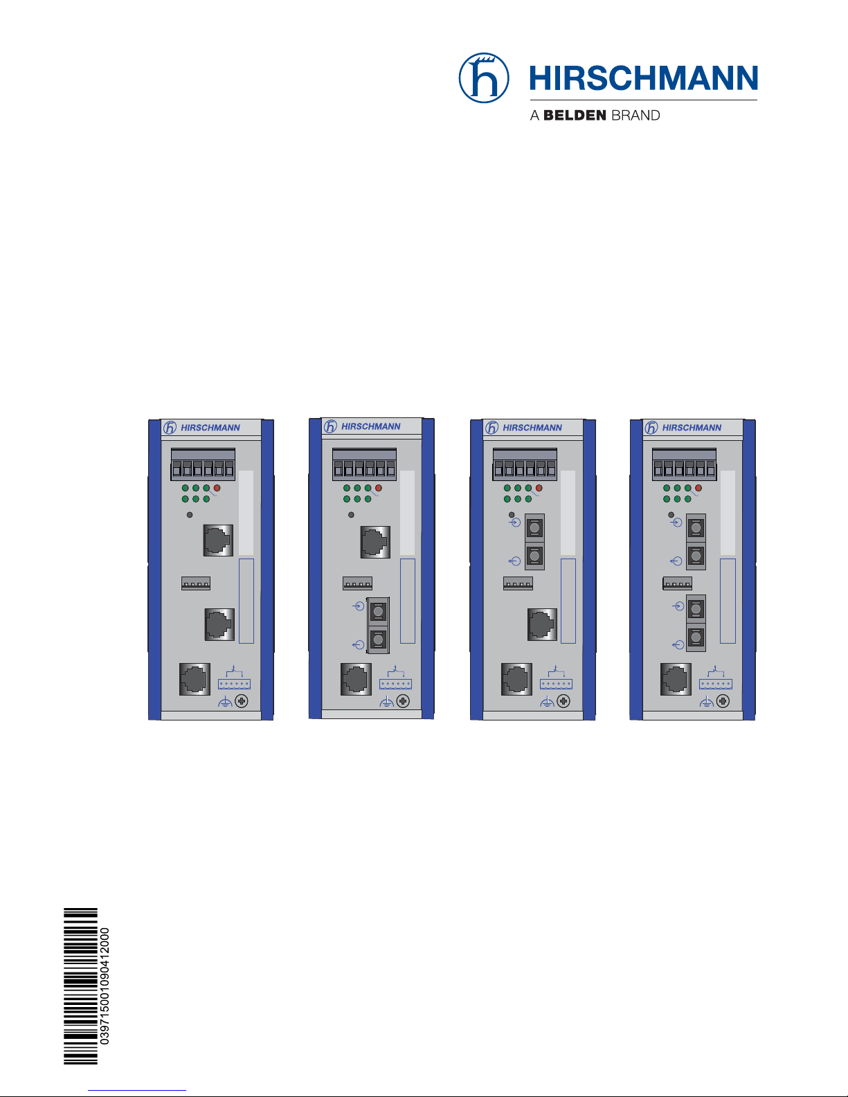
User Manual
Installation
Industrial ETHERNET Firewall
EAGLE 20
EAGLE 20 TX/TX
EAGLE 20 TX/MM
EAGLE 20 TX/SM
EAGLE 20 MM/TX
EAGLE 20 MM/MM
1
P
21
FAULT
LS/DA
21
k
STATUS
V.24
IP-ADDRESS
V.24
R
EAGLE 20
USB
+24V (P1)
FAULT
+24V (P2)
0V
0V
g
2
Aufkleber MAC-Adresse
1
P
21
FAULT
LS/DA
21
k
STATUS
V.24
IP-ADDRESS
V.24
R
EAGLE 20
USB
+24V (P1)
FAULT
+24V (P2)
0V
0V
g
2
Aufkleber MAC-Adresse
1
P
21
FAULT
LS/DA
21
k
STATUS
V.24
IP-ADDRESS
V.24
R
EAGLE 20
USB
+24V (P1)
FAULT
+24V (P2)
0V
0V
g
2
Aufkleber MAC-Adresse
1
P
21
FAULT
LS/DA
21
k
STATUS
V.24
IP-ADDRESS
V.24
R
EAGLE 20
USB
+24V (P1)
FAULT
+24V (P2)
0V
0V
g
2
Aufkleber MAC-Adresse
Page 2

The naming of copyrighted trademarks in this manual, even when not specially indicated, should
not be taken to mean that these names may be considered as free in the sense of the trademark
and tradename protection law and hence that they may be freely used by anyone.
© 2012 Hirschmann Automation and Control GmbH
Manuals and software are protected by copyright. All rights reserved. The copying, reproduction,
translation, conversion into any electronic medium or machine scannable form is not permitted,
either in whole or in part. An exception is the preparation of a backup copy of the software for
your own use. For devices with embedded software, the end-user license agreement on the
enclosed CD applies.
The performance features described here are binding only if they have been expressly agreed
when the contract was made. This document was produced by Hirschmann Automation and
Control GmbH according to the best of the company's knowledge. Hirschmann reserves the right
to change the contents of this document without prior notice. Hirschmann can give no guarantee
in respect of the correctness or accuracy of the information in this document.
Hirschmann can accept no responsibility for damages, resulting from the use of the network
components or the associated operating software. In addition, we refer to the conditions of use
specified in the license contract.
You can get the latest version of this manual on the Internet at the Hirschmann product site
(www.hirschmann.com).
Printed in Germany
Hirschmann Automation and Control GmbH
Stuttgarter Str. 45-51
72654 Neckartenzlingen
Germany
Tel.: +49 1805 141538
039 715-001-09-0412 – 20.4.12
Page 3

EAGLE 20
Release 09 04/2012
3
Contents
Safety instructions 4
About this manual 10
Key 10
1 Device description 11
1.1 General device description 11
1.2 Description of the device variants 13
1.2.1 Device variants with 2 TX ports 14
1.2.2 Device variants with 1 TX port and 1 FX port 14
1.2.3 Device variants with 1 FX port and 1 TX port 15
1.2.4 Device variants with 2 FX ports 15
2 Assembly and start-up 16
2.1 Installing the device 16
2.1.1 Overview of installation 16
2.1.2 Unpacking and checking 16
2.1.3 Terminal block for supply voltage and signal contact 17
2.1.4 Connecting the terminal block, start-up procedure 18
2.1.5 Installing the device on the DIN rail, grounding 18
2.1.6 Connecting the data lines 19
2.1.7 Connection to the network 21
2.2 Display elements 21
2.3 Controls 23
2.4 Basic set-up 23
2.5 Configuration 24
2.5.1 Firewall and VPN functions 24
2.5.2 Operating modes 25
2.5.3 Start configuration 27
2.6 Maintenance 28
2.7 Disassembly 29
3 Technical data 30
A Further Support 35
Page 4
4
EAGLE 20
Release 09 04/2012
Safety instructions
Important Information
Notice: Read these instructions carefully, and look at the equipment to
become familiar with the device before trying to install, operate, or
maintain it. The following special messages may appear throughout this
documentation or on the equipment to warn of potential hazards or to call
attention to information that clarifies or simplifies a procedure.
The addition of this symbol to a Danger or Warning safety label
indicates that an electrical hazard exists, which will result in
personal injury if the instructions are not followed.
This is the safety alert symbol. It is used to alert you to potential
personal injury hazards. Obey all safety messages that follow
this symbol to avoid possible injury or death.
Note: Contains important information on the product, on how to manage
the product, or on the respective section of the documentation to which
your special attention is being drawn.
DANGER
DANGER indicates an imminently hazardous situation which, if not
avoided, will result in death or serious injury.
WARNING
WARNING indicates a potentially hazardous situation which, if not avoided,
can result in death or serious injury.
CAUTION
CAUTION indicates a potentially hazardous situation which, if not avoided,
can result in minor or moderate injury.
Page 5

EAGLE 20
Release 09 04/2012
5
Certified usage
The device may only be employed for the purposes described in the
catalog and technical description, and only in conjunction with external
devices and components recommended or
approved by the manufacturer. The product can only be operated correctly and safely if it is transported, stored, installed and assembled properly and correctly. Furthermore, it must be operated and serviced
carefully.
Password security note
This device is a security product. For your own security, change the
password during the first startup procedure.
Supply voltage
For safety reasons the devices have been designed to operate at low
voltages. Thus, they may only be connected to the supply voltage
connections and to the signal contact with SELV circuits with the voltage
restrictions in accordance with IEC/EN 60950-1.
The supply voltage is electrically isolated from the housing.
Use undamaged parts.
Relevant for North America:
The device may only be connected to a supply voltage of class 2 that
fulfills the requirements of the National Electrical Code, Table 11(b). If
the voltage is being supplied redundantly (two different voltage
sources), the combined supply voltages must fulfill the requirements of
the National Electrical Code, Table 11(b).
Relevant for North America: For use in Class 2 circuits.
Only use copper wire/conductors of class 1, 140/167 °F (60/75 °C) or
167 °F (75 °C).
Shielding ground
The shielding ground of the connectable twisted pairs lines is connected
to the front panel as a conductor.
Beware of possible short circuits when connecting a cable section with
conductive shielding braiding.
Page 6
6
EAGLE 20
Release 09 04/2012
Housing
Only technicians authorized by the manufacturer are permitted to open
the housing.
The device housing is grounded by means of the separate ground screw.
(see fig. 1).
Make sure that the electrical installation meets local or nationally
applicable safety regulations.
The device must be installed in the vertical position (see fig. 8).
Install the device in a fire protected shell according to EN 60950-1.
Environment
The device may only be operated at the specified surrounding air
temperature (temperature of the surrounding air at a distance of up to
5 cm (1.97 in) from the device) and relative air humidity specified in the
technical data.
Install the device in a location where the climatic threshold values
specified in the technical data will be observed.
Use the device only in an environment within the pollution degree
specified in the technical data.
DANGER
HAZARD OF ELECTRIC SHOCK
Never insert sharp objects (small screwdrivers, wires, etc.) into the inside of
the product.
Failure to follow these instructions will result in death, serious injury,
or equipment damage.
CAUTION
EQUIPMENT OVERHEATING
When installing the device, make sure any ventilation slots remain free.
Maintain a clearance of at least 10 cm (3.94 in).
Failure to follow these instructions can result in injury or equipment
damage.
Page 7

EAGLE 20
Release 09 04/2012
7
Qualification requirements for personnel
Qualified personnel as understood in this manual and the warning signs,
are persons who are familiar with the setup, assembly, startup, and
operation of this product and are appropriately qualified for their job. This
includes, for example, those persons who have been:
trained or directed or authorized to switch on and off, to ground and to
label power circuits and devices or systems in accordance with current
safety engineering standards;
trained or directed in the care and use of appropriate safety equipment
in accordance with the current standards of safety engineering;
trained in providing first aid.
General safety instructions
Electricity is used to operate this equipment. Comply with every detail of
the safety requirements specified in the operating instructions regarding
the voltages to apply (see page 5).
Non-observance of these safety instructions can therefore cause material
damage and/or injuries.
Only appropriately qualified personnel should work on this device or in
its vicinity. These personnel must be thoroughly familiar with the
warnings and maintenance procedures in accordance with this
operating manual.
The proper and safe operation of this device depends on proper
handling during transport, proper storage and assembly, and
conscientious operation and maintenance procedures.
Never start operation with damaged components.
Only use the devices in accordance with this manual. In particular,
observe the warnings and safety-related information.
Any work that may be required on the electrical installation may only
be carried out by personnel trained for this purpose.
Note: LED or LASER components in compliance with IEC 60825-1
(2007):
CLASS 1 LASER PRODUCT
CLASS 1 LED PRODUCT
Light is emitted from the optical connections or from the ends of the
connected optical fibers that are connected to the optical connections.
LIGHT EMITTING DIODE CLASS 2 M, wave length 650 nm, power
<2 mW in accordance with DIN EN 60825-1:2003-10.
LIGHT EMITTING DIODE CLASS 1 - CLASS 1 LED PRODUCT
Page 8

8
EAGLE 20
Release 09 04/2012
National and international safety regulations
Make sure that the electrical installation meets local or nationally
applicable safety regulations.
CE marking
The devices comply with the regulations contained in the following
European directive(s):
2004/108/EC
Directive of the European Parliament and the council for standardizing
the regulations of member states with regard to electromagnetic
compatibility.
In accordance with the above-named EU directive(s), the EU conformity
declaration will be at the disposal of the relevant authorities at the
following address:
Hirschmann Automation and Control GmbH
Stuttgarter Str. 45-51
72654 Neckartenzlingen
Tel.: +49 1805 141538
The product can be used in the industrial sector.
Interference immunity: EN 61000-6-2:2005
Emitted interference: EN 55022:2010
Warning! This is a class A device. This device can cause interference in
living areas, and in this case the operator may be required to take
appropriate measures.
Note: The assembly guidelines provided in these instructions must be
strictly adhered to in order to observe the EMC threshold values.
FCC note:
This device complies with part 15 of FCC rules. Operation is subject to the
following two conditions : (1) This device may not cause harmful
interference; (2) this device must accept any interference received,
including interference that may cause undesired operation.
WARNING
EYE DAMAGE DUE TO LASER LIGHT
Do not look into the beam or view the beam directly with optical instruments
(magnifying glasses, microscope) at a distance of less than 100 mm
(3.94 in).
Failure to follow these instructions can result in death, serious injury,
or equipment damage.
Page 9

EAGLE 20
Release 09 04/2012
9
Appropriate testing has established that this device fulfills the
requirements of a class A digital device in line with part 15 of the FCC
regulations.
These requirements are designed to provide sufficient protection against
interference when the device is being used in a business environment.
The device creates and uses high frequencies and can radiate same, and
if it is not installed and used in accordance with this operating manual, it
can cause radio transmission interference. The use of this device in a
living area can also cause interference, and in this case the user is
obliged to cover the costs of removing the interference.
Recycling note
After usage, this product must be disposed of properly as electronic
waste, in accordance with the current disposal regulations of your county,
state and country.
Page 10

10
EAGLE 20
Release 09 04/2012
About this manual
The “Installation” user manual contains a device description, safety
instructions, a description of the display, and the other information that you
need to install the device.
The following manuals are available as PDF files on the CD-ROM supplied:
Installation user manual
Configuration user manual
Web-based Interface reference guide
Command Line Interface user manual
Key
The symbols used in this manual have the following meanings:
Listing
Workstep
Subheading
INTERNAL port
EXTERNAL port
Page 11

EAGLE 20
Release 09 04/2012
11
1 Device description
1.1 General device description
The industrial Firewall/VPN system
EAGLE 20 TX/TX
EAGLE 20 TX/MM
EAGLE 20 TX/SM
EAGLE 20 MM/TX
EAGLE 20 MM/MM
subsequently referred to as EAGLE 20, helps provide for the authentication,
security and confidentiality of communication within production networks, but
also beyond company boundaries.
The EAGLE 20 has the following interfaces:
depending on the type, up to two 10/100 Mbit/s twisted pair (TP/TX) ports
(RJ45 socket) and/or
depending on the type, up to two 100 Mbit/s FX ports (multimode or
singlemode) with DSC connections and
additionally a V.24 input for external management or a modem connection
and
a USB interface.
The EAGLE 20 supports the following network modes:
Transparent Mode
Router Mode
PPPoE Mode
The Industrial ETHERNET Firewall is used everywhere that securitysensitive network cells require a connection from the internal network into an
external network. The Industrial ETHERNET Firewall is the link between the
internal network and the external network from which unauthorized accesses
are to be expected. In its function as a link, the Industrial ETHERNET Firewall
helps protect the internal network from undesired data traffic along the
connection to the external network.
Typical uses are:
Helping protect individual production cells in a flat company network
Helping protect individual production cells in a routed company network
Coupling identical production cells to a company network
Connecting a production cell with the office network via a public network
Helping provide protected service access
Separation of machine common parts
Page 12

12
EAGLE 20
Release 09 04/2012
Figure 1: Overview of interfaces, display and operating elements on the EAGLE 20
1 - 6-pin terminal block, pluggable
2 - LED display elements
3 - Reset button
4 - IP address field
5 - Port 1: Depending on device model,
TX (RJ45 connector) and/or FX (DSC connector)
6 - USB connection
7 - Port 2: Depending on device model,
TX (RJ45 connector) and/or FX (DSC connector)
8 - MAC address field
9 - V.24 interface: external management and modem
10 - Grounding screw
The devices are designed for the special requirements of industrial
automation. They meet the relevant industry standards, provide high
operational reliability, even under extreme conditions, and also long-term
reliability and flexibility. The devices operate without fans and have a
redundant voltage supply. The devices are quickly mounted by snapping
them onto a DIN rail, which also automatically contacts the function ground.
The devices provide you with a large range of features:
Firewall (FW)
Virtual Private Network (VPN) functions
ARP Limiter
Redundancy support
ACA 21-USB support
1
P
21
FAULT
LS/DA
21
k
STATUS
V.24
IP-ADDRESS
V.24
R
EAGLE 20
USB
+24V (P1)
FAULT
+24V (P2)
0V
0V
g
2
Aufkleber MAC-Adresse
1
2
3
4
5
6
7
8
9
10
Page 13

EAGLE 20
Release 09 04/2012
13
Management: HTTPS, SNMPv1, SNMPv2, SNMPv3, SSH, V.24
Redundant power supply
Temperature range: 0°C – 60°C, without fan
Housing: mountable on DIN rail, IP20
1.2 Description of the device variants
These devices can be managed. They have the following properties:
Voltage range: 12 to 48 V DC or 24 V AC
Temperature range: +32 °F to +140 °F (0 °C to +60 °C)
The device conforms to the specifications of standard
ISO/IEC 8802-3u 100BASE-TX
ISO/IEC 8802-3 100BASE-FX
The device contains the function units, such as: Firewall/VPN function,
Management function, voltage connection, management connection (V.24),
operation element (reset button).
Interfaces
Device Port 1 (INTERNAL) Port 2 (EXTERNAL)
TX MM SM TX MM SM
EAGLE 20 TX/TX X ——X ——
EAGLE 20 TX/MMX ———X —
EAGLE 20 TX/SM X ————X
EAGLE 20 MM/TX—X —X ——
EAGLE 20 MM/MM—X ——X —
Table 1: Interfaces of the EAGLE 20 types
TX = Twisted pair 100BASE-TX
MM = F/O multimode 100BASE-FX
SM = F/O singlemode 100BASE-FX
Page 14

14
EAGLE 20
Release 09 04/2012
1.2.1 Device variants with 2 TX ports
Figure 2: Interfaces of the EAGLE 20 TX/TX
1 - Port 1 (INTERNAL port): 100BASE-TX, RJ45 connector,
Autonegotiaton, autopolarity, autocrossing
2 - Port 2 (EXTERNAL port): 100BASE-TX, RJ45 connector,
Autonegotiaton, autopolarity, autocrossing
1.2.2 Device variants with 1 TX port and 1 FX port
Figure 3: Interfaces of the EAGLE 20 TX/MM and EAGLE 20 TX/SM
1 - Port 1 (INTERNAL port): 100BASE-TX, RJ45 connector,
Autonegotiaton, autopolarity, autocrossing
2 - Port 2 (EXTERNAL port): 100BASE-FX, DSC connector,
Multimode (EAGLE 20 TX/MM) or singlemode (EAGLE 20 TX/SM)
1
P
21
FAULT
LS/DA
21
k
STATUS
V.24
IP-ADDRESS
V.24
R
EAGLE 20
USB
+24V (P1)
FAULT
+24V (P2)
0V
0V
g
2
Aufkleber MAC-Adresse
1
2
1
P
21
FAULT
LS/DA
21
k
STATUS
V.24
IP-ADDRESS
V.24
R
EAGLE 20
USB
+24V (P1)
FAULT
+24V (P2)
0V
0V
g
2
Aufkleber MAC-Adresse
1
2
Page 15

EAGLE 20
Release 09 04/2012
15
1.2.3 Device variants with 1 FX port and 1 TX port
Figure 4: Interfaces of the EAGLE 20 MM/TX
1 - Port 1 (INTERNAL port): 100BASE-FX, DSC connector, Multimode
2 - Port 2 (EXTERNAL port): 100BASE-TX, RJ45 connector,
Autonegotiaton, autopolarity, autocrossing
1.2.4 Device variants with 2 FX ports
Figure 5: Interfaces of the EAGLE 20 MM/MM
1 - Port 1 (INTERNAL port): 100BASE-FX, DSC connector, Multimode
2 - Port 2 (EXTERNAL port): 100BASE-FX, DSC connector, Multimode
1
P
21
FAULT
LS/DA
21
k
STATUS
V.24
IP-ADDRESS
V.24
R
EAGLE 20
USB
+24V (P1)
FAULT
+24V (P2)
0V
0V
g
2
Aufkleber MAC-Adresse
1
2
1
P
21
FAULT
LS/DA
21
k
STATUS
V.24
IP-ADDRESS
V.24
R
EAGLE 20
USB
+24V (P1)
FAULT
+24V (P2)
0V
0V
g
2
Aufkleber MAC-Adresse
1
2
Page 16

16
EAGLE 20
Release 09 04/2012
2 Assembly and start-up
2.1 Installing the device
Before installing and starting up the device, note the safety instructions (see
page 5 onwards).
2.1.1 Overview of installation
Two or more devices configured with the same IP address can cause
unpredictable operation of your network.
The devices have been developed for practical application in a harsh
industrial environment.
On delivery, the device is ready for operation.
The following steps should be performed to install and configure a EAGLE 20
Industrial ETHERNET Firewall product:
Unpacking and checking
Connect the terminal block for voltage supply and signal
contact and connect the supply voltage
Install the terminal block, start-up procedure
Install the device on the DIN rail, grounding
Connect the data lines
2.1.2 Unpacking and checking
Check that the contents of the package are complete (see page 33
“Scope of delivery”).
Check the individual parts for transport damage.
WARNING
UNINTENDED EQUIPMENT OPERATION
Establish and maintain a process for assigning unique IP addresses to all
devices on the network.
Failure to follow these instructions can result in death, serious injury,
or equipment damage.
Page 17

EAGLE 20
Release 09 04/2012
17
2.1.3 Terminal block for supply voltage and signal contact
The supply voltage and the signal contact are connected via a 6-pin terminal
block with a snap lock.
Supply voltage
Redundant power supplies can be used. Both inputs are uncoupled.
There is no distributed load. With redundant supply, the power supply unit
supplies the device only with the higher output voltage. The supply
voltage is electrically isolated from the housing.
You can choose between DC or AC voltage when connecting the supply
voltage. You use the +24 V and 0 V pins to connect the AC voltage (fig. 6
and fig. 7).
Note: With non-redundant supply of the main voltage, the device reports
a loss of power. You can avert this message by applying the supply
voltage via both inputs, or by changing the configuration in the
Management.
Figure 6: Pin assignment of the 6-pin terminal block, DC connection
DANGER
HAZARD OF ELECTRIC SHOCK OR BURN
When the module is operated with direct plug-in power units, use only:
– SELV supply units that comply with IEC 60950/EN 60950 and
– (in USA and Canada) Class 2 power units that comply with applicable
national or regional electrical codes
Connect the ground wire to the PE terminal (where applicable) before you
establish any further connections. When you remove connections,
disconnect the ground wire last.
Failure to follow these instructions will result in death, serious injury,
or equipment damage.
FAULT
12 ... 48 V DC12 ... 48 V DC
+24V(P1) 0V 0V +24V(P2)
+-
-+
Page 18

18
EAGLE 20
Release 09 04/2012
Figure 7: Pin assignment of the 6-pin terminal block, AC connection
Signal contacts
The signal contact (“FAULT”, for pin assignment see fig. 6 and fig. 7)
is used for the remote monitoring of the device to enable remote
diagnostics. You can specify the type of function monitoring in the
Management.
You can also use the Management to set the signal contact manually
and thus control external devices.
A break in contact is used to report the following conditions via the
potential-free signal contact (relay contact, closed circuit):
The detected inoperability of at least one of the two voltage supplies
(voltage supply 1 or 2 is below the threshold value).
A continuous detected error in the device (internal supply voltage).
The detected error of the link status of at least one port. The report of
the link status can be masked by the Management for each port. In the
default state, link status monitoring is deactivated.
The temperature of the device is outside the range specified in the
threshold values.
The removal of the ACA.
2.1.4 Connecting the terminal block, start-up procedure
Pull the terminal block off the device and connect the voltage supply lines
and the signal lines.
Startup procedure
Mount the terminal block for the voltage supply and signal contact on
the front of the device by snapping the lock into place.
Connecting the voltage supply via the terminal block starts the operation
of the device.
2.1.5 Installing the device on the DIN rail, grounding
Mount the device on a 35 mm DIN rail in accordance with DIN EN 60175.
Attach the upper snap-in guide of the device into the DIN rail and press it
down against the DIN rail until it snaps into place.
FAULT
G
24 V AC
G
24 V AC
+24V(P1) 0V 0V +24V(P2)
Page 19

EAGLE 20
Release 09 04/2012
19
Note: The shielding ground of the industrial connectable twisted pair lines is
connected to the front panel as a conductor.
Figure 8: Mounting on the DIN rail
Grounding
The device housing is grounded by means of the separate ground screw.
(see fig. 1).
2.1.6 Connecting the data lines
10/100 Mbit/s twisted pair connection
These connections are RJ45 sockets.
10/100 Mbit/s TP ports enable the connection of terminal devices or
independent network segments according to the IEEE 802.3 10BASE-T/
100BASE-TX standard.
These ports support:
Autonegotiation
Autopolarity
Autocrossing (if autonegotiation is activated)
100 Mbit/s half-duplex mode, 100 Mbit/s full duplex mode
10 Mbit/s half-duplex mode, 10 Mbit/s full duplex mode
State on delivery: autonegotiation activated.
The socket housing is electrically connected to the front panel.
Page 20

20
EAGLE 20
Release 09 04/2012
100 Mbit/s F/O connection
These connections are DSC connectors.
100 MBit/s F/O ports enable the connection of terminal devices or
independent network segments in compliance with the IEEE 802.3
100BASE-FX standard.
These ports support:
Full or half duplex mode
State on delivery: full duplex FDX
Note: Make sure that the SM ports are only connected with SM ports, and
MM ports only with MM ports.
Note: LED or LASER components in compliance with IEC 60825-1
(2007):
CLASS 1 LASER PRODUCT
CLASS 1 LED PRODUCT
Light is emitted from the optical connections or from the ends of the
connected optical fibers that are connected to the optical connections.
LIGHT EMITTING DIODE CLASS 2 M, wave length 650 nm, power
<2 mW in accordance with DIN EN 60825-1:2003-10.
LIGHT EMITTING DIODE CLASS 1 - CLASS 1 LED PRODUCT
Figure Pin Function
1+2 One line pair: receiver path
3+6 One line pair: sender path
4,5,7,8 Not used
Table 2: Pin assignment of a TP/TX interface in MDI-X mode, RJ45 socket
WARNING
EYE DAMAGE DUE TO LASER LIGHT
Do not look into the beam or view the beam directly with optical instruments
(magnifying glasses, microscope) at a distance of less than 100 mm
(3.94 in).
Failure to follow these instructions can result in death, serious injury,
or equipment damage.
8
7
6
5
4
3
2
1
Page 21

EAGLE 20
Release 09 04/2012
21
2.1.7 Connection to the network
Connect the device via the INTERNAL port to the internal network or the
local computer that you want to help protect.
Connect the device via the EXTERNAL port to the external network, e.g.
the Internet. This network is used to set up the connections to the external
device or external network.
2.2 Display elements
After the operating voltage is applied, the software starts and initializes itself.
Afterwards, the device performs a self-test. During these actions, the
STATUS LED flashes. The process takes around 40 seconds.
STATUS
P
21
LS/DA
21
FAULT
V.24
Page 22

22
EAGLE 20
Release 09 04/2012
Device state
These LEDs provide information about conditions which affect the
operation of the whole device.
Port state
These LEDs display port-related information.
P1 - Power 1 (green LED)
Glowing green Supply voltage 1 is present
Not glowing Supply voltage 1 is too low
P2 - Power 2 (green LED)
Glowing green Supply voltage 2 is present
Not glowing Supply voltage 2 is too low
FAULT - detected error, signal contact (red LED)
a
a. If the manual adjustment is active on the “FAULT” signal contact, then the detected error
display is independent of the setting of the signal contact.
Glowing red The signal contact is open, i.e. it is reporting a detected error.
Not glowing The signal contact is closed, i.e. it is not reporting
a detected error.
STATUS (green/yellow LED)
Flashing green Initialization phase of the device.
Glowing green Device is ready for operation.
Slowly flashing yellow The device is in Router Redundancy Backup Mode.
Glowing yellow The device is operating in the Router Redundancy Master
Mode and there is no communication with the backup device
Flashing alternately green and
yellow
(1 change per second)
The VPN status indication is switched on and at least
1 VPN connection is active. The flashing of the STATUS LED
as an indication of ACA loading or ACA saving operations
takes precedence over the flashing as an indication of
VPN connections.
STATUS and V.24 - saving
processes of the
AutoConfiguration Adapter
(ACA)
Flashing alternately Detected error during saving process.
LEDs flash synchronously, two
times a second
Loading configuration from the ACA.
LEDs flash synchronously,
once a second
Saving the configuration in the ACA.
LS/DA, V.24 - data, link status
(green/yellow LEDs)
Meaning
Not glowing No valid connection.
Glowing green Valid connection.
Flashing green (3 times a
period)
Port is switched off.
Flashing yellow Data reception.
Page 23

EAGLE 20
Release 09 04/2012
23
2.3 Controls
The EAGLE 20 has a Reset button (see fig. 1).
Reset button R (restart)
The reset button is used to restart the device.
To perform the restart, press the reset button for longer than 1.5
seconds until the STATUS LED goes dark and the FAULT LED lights
up red.
Note: The system monitor is used to flash the software. You will find a
more detailed description of how to perform this action in the
“Configuration” user manual of the EAGLE 20.
2.4 Basic set-up
Enter the IP parameters when you install the device for the first time. The
device provides multiple options for configuring IP addresses:
Entry via V.24 connection
Entry via the HiDiscovery protocol via the application HiDiscovery or
Industrial HiVision (via the internal port)
Auto Configuration Adapter
Web Interface
Further information on the basic settings of the device can be found in the
“Configuration” user manual on the CD ROM.
Default settings
IP address: DHCP default setting off
Static IP address: 192.168.1.1/24
Management password:
user, password: public (read only)
admin, password: private (read and write)
V.24 data rate: 9,600 Baud
Ethernet ports: link status is not evaluated (signal contact)
Optical 100 Mbit/s ports: 100 Mbit/s full duplex
Other ports: autonegotiation
USB interface
The USB socket has an interface for the local connection of an
AutoConfiguration Adapter ACA 21-USB or another approved USB
storage device. It is used for saving and loading the configuration and for
updating the software.
Page 24

24
EAGLE 20
Release 09 04/2012
V.24 interface (external management)
A serial interface is provided on the RJ11 socket (V.24 interface) for the
local connection of an external management station (VT100 terminal or
PC with corresponding terminal emulation). This enables you to set up a
connection to the Command Line Interface (CLI) and to the system
monitor.
The socket housing is electrically connected to the housing of the device.
Figure 9: Pin assignment of the V.24 interface and the DB9 connector
Note: You will find the order number for the terminal cable, which is
ordered separately, in the Technical Data chapter (see on page 30
“Technical data”).
2.5 Configuration
2.5.1 Firewall and VPN functions
Firewall functions
The EAGLE 20 supports the following firewall functions:
Stateful Inspection Firewall
Transparent Firewall
Contact number Signal name
1VCC
2 - Data
3 + Data
4 Ground
VT 100 terminal settings
Speed 9,600 Baud
Data 8 bit
Stopbit 1 bit
Handshake off
Parity none
1
1
8
5
6
2
3
5
1
2
3
4
5
6
CTS
n.c.
TX
GND
RX
RTS
RJ11
DB9
RJ11
DB9
Page 25

EAGLE 20
Release 09 04/2012
25
Configurable Firewall rules:
Incoming/outgoing data traffic
Modem access
External Management access
IP Masquerading, 1-to-1 NAT, Port Forwarding
IP Spoofing Protection
VPN functions
The EAGLE 20 supports the following Virtual Private Network (VPN)
functions:
Multipoint VPN: Router Mode
VPN protocols: IPsec
Encryption algorithms:
DES-56
3DES-168
AES-128, AES-192, AES-256
Authentication:
Pre-shared key (PSK)
X.509v3 certificates
Hashing algorithms: MD5, SHA-1
NAT-T support
2.5.2 Operating modes
This device helps protect the internal network from the influences of the
external network. These influences can include unauthorized access
attempts, as well as interfering network events such as overloads.
State on delivery
On delivery, the device works in the Transparent Mode. In this mode, no
network settings (e.g., for subnetworks) are required for operation.
The firewall has been preconfigured so that the IP data traffic from the
internal network is possible; however, traffic from the external network to
the internal network is not possible. Thus, already the delivery state helps
protect against unauthorized accesses from the external network.
Transparent Mode
The Transparent Mode is a transparent bridge mode. In this mode, the
device works as a 2-port bridge, whereby only IP and ARP frames
corresponding to the firewall rules are transmitted.
Page 26

26
EAGLE 20
Release 09 04/2012
In the state on delivery, you can access the device via address
192.168.1.1/24 without configuring the IP address.
Router Mode
In Router Mode, the device works as a 2-port router. You will find a
detailed description of the IP configuration in the “Configuration” user
manual of the EAGLE 20.
Note: In the Router and Transparent modes, an additional network
access option to the internal network is provided over the V.24 interface
of the EAGLE 20, via PPP. In this case, communication is possible with
the EAGLE 20 itself or with the devices in the internal network (according
to the firewall rules for the modem connection).
PPPoE Mode
In PPPoE Mode, the EAGLE 20 works like in the router mode, with the
difference that the PPPoE protocol is used at the external port. This
enables Internet connections via a DSL modem, for example.
Page 27

EAGLE 20
Release 09 04/2012
27
2.5.3 Start configuration
To access the EAGLE 20, you proceed as follows (device in state on
delivery):
Install the required Java plug-in on your computer.
You will find information about the plug-in and its installation in the
Configuration user manual.
Start an https-capable Web browser on the computer connected to the
internal port (e.g. Mozilla Firefox from version 1.5 on, or Microsoft Internet
Explorer from version 6 on) in order to configure the EAGLE 20.
Connect the external port to your network.
Enter the following address in the Web browser:
https://192.168.1.1/
Result: The HTTPS connection to the EAGLE 20 is set up. A security
message is displayed.
Confirm the security message with “Yes”.
To login, enter:
– Login: admin
– Password: private
(case-sensitive!)
Result: The Administrator website of the EAGLE 20 is displayed.
Configure the device in accordance with the Configuration user manual.
Alternatively, you can perform the IP configuration for the Transparent Mode
using the HiDiscovery protocol. You will find the HiDiscovery software on the
CD ROM included in the delivery.
Note: If the configuration connection to the EAGLE 20 is not set up, you will
find detailed information in the “Configuration User Manual - Industrial
ETHERNET Firewall EAGLE 20”.
Figure 10: Configuration before the installation of the EAGLE 20
Page 28

28
EAGLE 20
Release 09 04/2012
Figure 11: Configuration after the installation of the EAGLE 20
2.6 Maintenance
Depending on the degree of pollution in the operating environment, check at
regular intervals that the ventilation slots in the device are not obstructed.
When designing this device, Hirschmann was largely able to forego using
wear parts. The parts subject to wear are dimensioned to last longer than the
lifetime of the product when it is operated normally. Operate this device
according to the specifications (see “Technical data”).
Relays are subject to natural wear. This wear depends on the frequency of
the switching operations. Depending on the frequency of the switching
operations, check the volume resistance of the closed relay contacts and the
switching function.
Hirschmann are continually working on improving and developing their
software. You should regularly check whether there is a new version of the
software that provides you with additional benefits. You will find software
information and downloads on the product pages of the Hirschmann website.
2
1
Page 29

EAGLE 20
Release 09 04/2012
29
2.7 Disassembly
Disassembling the device
In order to remove the device from the DIN rail, move the screwdriver
horizontally under the chassis in the locking gate, pull this down without tilting the screwdriver - and fold the device up.
Figure 12: Disassembly
Page 30

30
EAGLE 20
Release 09 04/2012
3 Technical data
General technical data
Dimensions
W × H × D
EAGLE 20... 2.36 in. × 5.71 in. × 4.92 in.
(60 mm × 145 mm × 125 mm)
Weight EAGLE 20... 21.16 oz - 22.22 oz (depending on variant)
(600 g - 630 g)
Power supply Redundant power supply
Safety extra-low voltage (SELV), redundant inputs disconnected.
Relevant for North America: NEC Class 2 power source max. 5A.
Operating voltage Rated voltage range DC
12 to 48 V DC
Max. voltage range DC
min. 9.6 to max. 60 V DC
Rated voltage range AC
24 V AC
Max. voltage range AC
min. 18 to max. 30 V AC
Back-up fuse Nominal rating:
3,15 A for each voltage input
Characteristic:
slow blow
Insulation voltage between operating voltage
connections and housing
800 V DC
Protective elements limit the insulation
voltage to 90 V DC (1 mA)
“FAULT”
signal contact
Switching current max. 1 A, SELV
Switching voltage max. 60 V DC or max. 30 V AC, SELV
Relevant for North America: NEC Class 2
Environment Storage temperature
(ambient air)
−40 °F ... +158 °F (−40 °C ... +70 °C)
Humidity 10% ... 95%
(non-condensing)
Air pressure Up to 2000 m (795 hPa), higher altitudes
on request
Operating
temperature
Surrounding air +32 °F ... +140 °F (0 °C ... +60 °C)
Protection classes Laser protection Class 1 according to EN 60825-1 (2007)
Protection class IP 20
Mounting 35 mm DIN rail (DIN EN 60175)
Pollution degree 2
Page 31

EAGLE 20
Release 09 04/2012
31
EMC and immunity
Network range
EMC interference
immunity
EN 61000-4-2 Electrostatic discharge
Contact discharge
Air discharge
4 kV
8 KV
EN 61000-4-3 Electromagnetic field
80 - 2,700 MHz 10 V/m
EN 61000-4-4 Fast transients (burst)
- Power line
- Data line
2 kV
1 kV
EN 61000-4-5 Voltage surges
- Power line, line/line
- Power line, line/earth
- Data line
0.5 kV
1 kV
1 kV
EN 61000-4-6 Line-conducted interference voltages
150 kHz - 80 MHz 10 V
EN 61000-4-9 Impulse-shaped magnetic fields -
EMC emitted
interference
EN 55022 Class A Yes
FCC 47 CFR Part 15 Class A Yes
Germanischer Lloyd Classification and Construction Guidelines VI-7-3 Part 1 -
Stability
Vibration IEC 60068-2-6 Test FC test level according to IEC 61131-2 Yes
Germanischer Lloyd Guidelines for the Performance of Type
Tests Part 1
-
IEC 870-2-2 table 3 normal, requirements according to
EN61850-3
-
EN 61373, Category 1, Class A (broadband noise),
requirements according to EN 50155
-
Shock IEC 60068-2-27 Test Ea test level according to IEC 61131-2 Yes
IEC 870-2-2 table 3 normal, requirements according to
EN61850-3
-
EN 61373, Category 1, Class A
requirements according to
EN 50155
-
TP port
Length of a twisted pair segment max. 100 m
Table 3: TP port 10BASE-T / 100BASE-TX
Page 32

32
EAGLE 20
Release 09 04/2012
MM = Multimode
SM = Singlemode
Power consumption/power output
Order numbers
Interfaces
Ports Wave
length
Fiber System
attenuati
on
Example
for F/O
line
length
a
a. including 3 dB system reserve when compliance with the fiber data is observed
Fiber
attenuation
BLP/
dispersion
MM 1300 nm 50/125 µm 0-8 dB 0-5 km 1.0 dB/km 800 MHz*km
MM 1300 nm 62.5/125 µm 0-11 dB 0-4 km 1.0 dB/km 500 MHz*km
SM 1300 nm 9/125 µm 0-16 dB 0-30 km 0.4 dB/km 3.5 ps/(nm*km)
Table 4: LWL port 100BASE-FX
Device variant Power
consumption
at 24 V DC
Power output
at 24 V DC
Power
consumption
at 24 V AC
Power output
at 24 V AC
...TX/TX 6.9 W 23.5 Btu (IT)/h 7.2 W 24.6 Btu (IT)/h
...TX/MM
...MM/TX
...TX/SM
8.1 W 27.6 Btu (IT)/h 8.1 W 27.6 Btu (IT)/h
...MM/MM 9.5 W 32.4 Btu (IT)/h 9.6 W 32.8 Btu (IT)/h
Device Order number
EAGLE 20 TX/TX 943 987-001
EAGLE 20 TX/MM 943 987-002
EAGLE 20 TX/SM 943 987-003
EAGLE 20 MM/TX 943 987-004
EAGLE 20 MM/MM 943 987-005
EAGLE 20... V.24 port: external management, modem
terminal block, 6-pin: signal contact, max. 1 A, 24 V
and voltage supply
USB interface: ACA 21-USB
Additionally 2 typedependent ports each
Up to two 10/100 Mbit/s twisted pair (TP/TX) ports with RJ45
sockets and/or up to two 100 Mbit/s FX ports (multimode or
singlemode) with DSC connections
Page 33

EAGLE 20
Release 09 04/2012
33
Scope of delivery
Accessories
Note: Please note that products recommended as accessories may have
characteristics that do not fully comply with those of the corresponding
product. This may limit their possible usage in the overall system.
Underlying norms and standards
EAGLE 20 device
Terminal block 6-pin
Connection Power supply
Signal contact
CD ROM with user manual
Installation user manual
Name Order number
AutoConfiguration Adapter ACA 21-USB EEC 943 271-002
Terminal cable 943 301-001
6-pin terminal block 943 845-002
Rail Power Supply RPS 30 943 662-003
Rail Power Supply RPS 80 EEC 943 662-080
Rail Power Supply RPS 120 EEC 943 662-120
Industrial HiVision Network Management software 943 156-xxx
Name
EN 61000-6-2 Generic norm – immunity in industrial environments
EN 55022 IT equipment – radio interference characteristics
EN 60950-1 Safety for the installation of IT equipment
EN 61131-2:2008 Programmable logic controllers
EN 50121-4:2000 Railway applications - EMC - emitted interference and
interference immunity for signal and telecommunication systems
FCC 47 CFR Part 15 Code of Federal Regulations
German Lloyd Classification and Construction Guidelines VI-7-3 Part 1 Ed.2003
cUL 508:1998 Safety for Industrial Control Equipment
EN 60079-15 Electrical equipment for explosive gas atmospheres – part 15:
Construction, testing and marking of protection type "n" electrical
apparatus.
EN 50155 Declaration (Railways)
IEC/EN 61850-3 Communications networks and systems in substations
IEEE 1613 Standard Environment and Testing Requirements for
Communication Networking Devices in Electric Power
Substations
Table 5: List of norms and standards
Page 34

34
EAGLE 20
Release 09 04/2012
The device has a certification based on a specific standard only if the
certification indicator appears on the housing.
However, with the exception of Germanischer Lloyd, ship certifications
are only included in the product information under www.hirschmann.com.
IEEE 802.1AB Topology Discovery (LLDP)
IEEE 802.3-2002 Ethernet
IEEE 802.3ac VLAN Tagging
Table 6: List of IEEE norms
Page 35

EAGLE 20
Release 09 04/2012
35
A Further Support
Technical Questions
For technical questions, please contact any Hirschmann dealer in your
area or Hirschmann directly.
You will find the addresses of our partners on the Internet at
http://www.hirschmann.com
Contact our support at
https://hirschmann-support.belden.eu.com
You can contact us
in the EMEA region at
Tel.: +49 (0)1805 14-1538
E-mail: hac.support@belden.com
in the America region at
Tel.: +1 (717) 217-2270
E-mail: inet-support.us@belden.com
in the Asia-Pacific region at
Tel.: +65 68549860
E-mail: inet-ap@belden.com
Hirschmann Competence Center
The Hirschmann Competence Center is ahead of its competitors:
Consulting incorporates copmprehensive technical advice, from
system evaluation through network planning to project planning.
Training offers you an introduction to the basics, product briefing and
user training with certification.
The current training courses to technology and products can be found
at http://www.hicomcenter.com
Support ranges from the first installation through the standby service
to maintenance concepts.
With the Hirschmann Competence Center, you have decided against
making any compromises. Our client-customized package leaves you
free to choose the service components you want to use.
Internet:
http://www.hicomcenter.com
Page 36

 Loading...