

Page 1
User’s Manual
DIGITAL CABLE NETWORK TERMINAL
WITH COMMON INTERFACE
CSR 3402 QAM
MENU
OK
Page 2

CONTENTS
1. Features ------------------------------------- --------------------------- ------------- 2
2.
Front & Rear View ------------------------- --------------------------------------- 3
3. Remote Control Unit (RCU) ---------------------------------------------------- 4
4. Getting Star ted ----------------------------------------- ---------------------------- 5
Operation and Menu Program ------------------------------------------------- 7
5.
Specifications ---------------------------------------------------------------------- 16
6.
AC power switch is on the rear panel of the receiver.
AC power switch is on the rear panel of the receiver.
Trade Mark of the DVB Digital Video Broadcasting Project (1700)
1
Page 3

1. Features
1. MPEG 2 Video(MP@ML)
2. MPEG 1 Audio Layer 1, Layer 2
3. MPEG-2 Digital & Fully DVB Compliant
4. Capable of Interfacing the CAMs of DVB Common Interface Standard
5. Automatic Channel Set-up for CATV network
6. Capable of Auto scanning the frequency for QPSK to QAM Conversion system
7. QAM demodulation
8. On-Screen Display with 256-Color Full Resolution
9. LD Quality Video, CD Quality Audio
10. Plug & Play Installation
11. Parental lock
12. RS232C port for additional information service and updating IRD control software
13. 4-digit 7-segment LEDs on the front panel displays channel information
14. Displays Local Time on the front panel, when it is on stand-by mode
15. Power recovery function
16. 64-Step Volume control
17. Favorite channel function
18. User friendly OSG menu with full function
19. IR remo te control
20. Last channel memory function
21. Variable aspect ratio (4:3, 16:9) with Pan vector
22. EPG for on-screen channel information
23. Receiver-to-Receiver function for operating program and data transfer.
2
Page 4
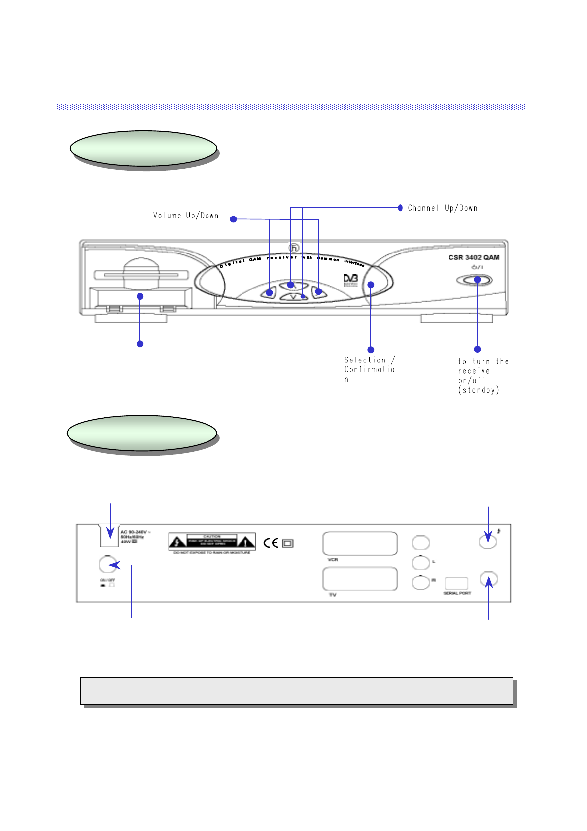
2. Front & Rear View
FRONT PANEL
2 CAM Slots
REAR PANEL
AC Power
Cord
MENU
OK
Cable Input
VIDEO
ANT IN
AUDIO
TV/VCR
AC power switch
Loop Through
Note) All cables used for connecting the receiver should be well-shielded type cable.
3
Page 5
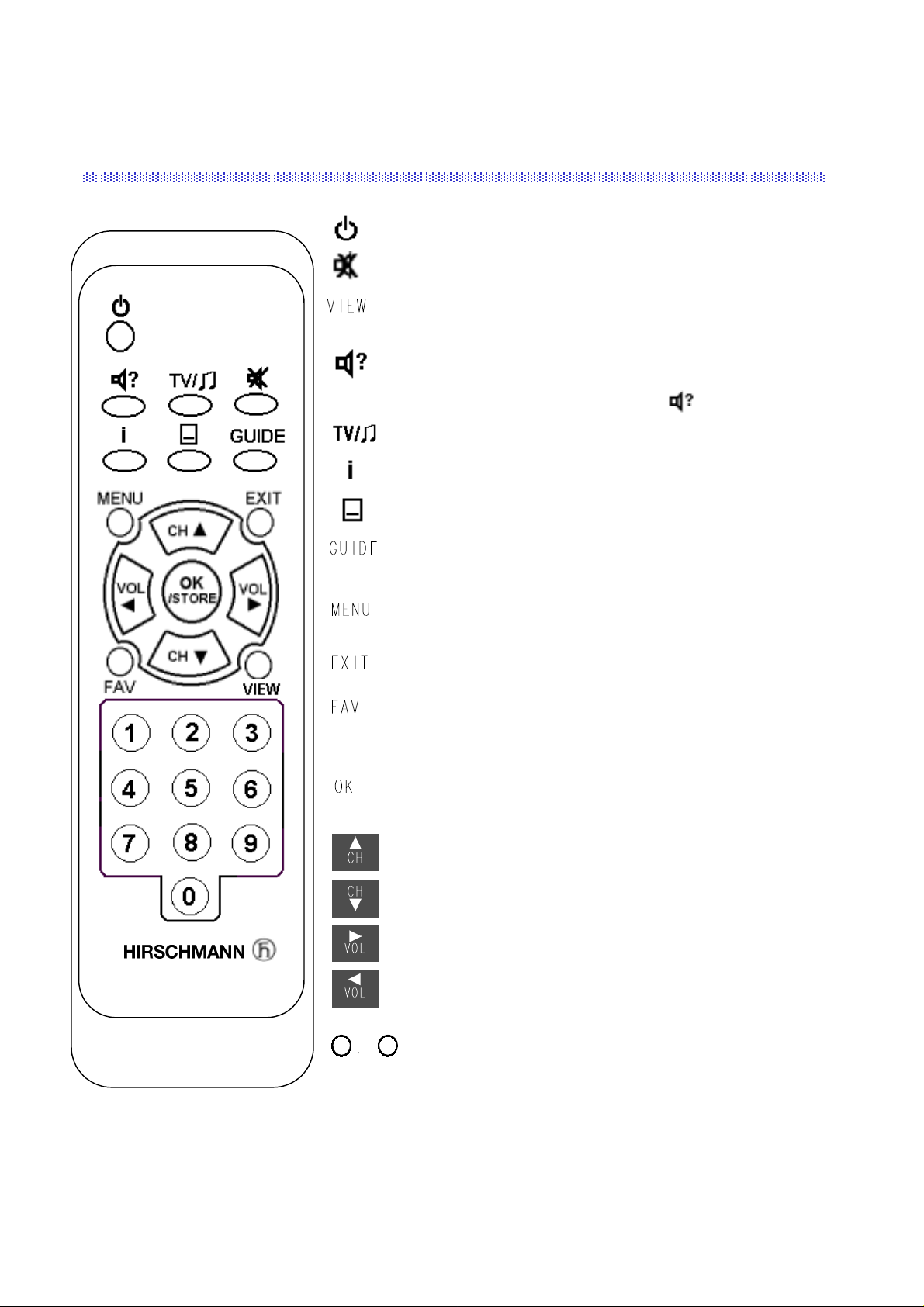
3. Remote Control Unit (RCU)
Switches the Receiver ON/OFF
Switches the sound ON/OFF.
Shows a thumb nail representation of the current channel in the
“Edit TV Channel”, “Parental Lock” and “TV Guide”.
Select the audio language or the sound track you want
among data to be transmitted from the satellite.
To return to current channel, press or EXIT.
Switches between TV/Radio mode.
Shows program information provided by the broadcaster
Shows Subtitle menu to select the subtitle language.
Shows the list of available channels.
(Only available when provided by the broadcaster)
When you want to see the main menu or
return to the previous menu.
Return to the current video viewing at any time
Shows your favo ri te c h an nels edited.
(Before the operation, FAV edition should be done
in “Edit TV channel” menu.)
Selection of program, highlighted line or parameter value.
Also, you can see TV/Radio channel list while watching TV
or listening to Radio channel.
Channel Up
Channel Down
Volume Up (Page Up )
Volume Down (Page Down)
9
0
Direct choice of TV / Radio channel and other commands by
numeric keys.
4
Page 6
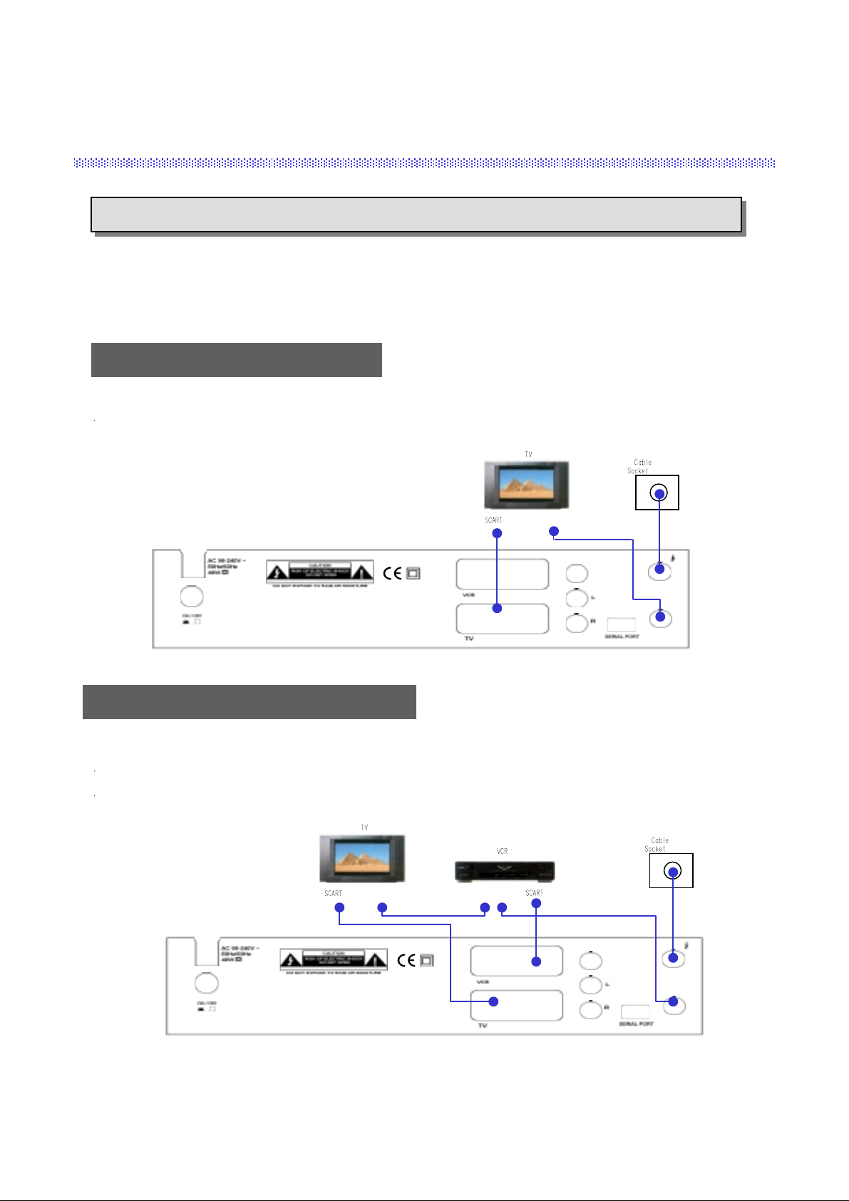
4. Getting Started
Please do NOT PLUG the receiver into Mains until you finish making all connections to the unit.
Connect the coaxial cable from the Cable socket into ANT IN socket of the receiver.
(Connector should be adapted finger-tight.)
Receiver to TV with SCART
Connect the
“TV” SCART on the receiver with the SCAR T of TV
Receiver to VCR, TV with SCART
Connect the
Connect the
“TV” SCART on the receiver with the SCAR T of TV
“VCR” SCART on the receiver with the SCART of VCR
.
RF Connector
VIDEO
ANT IN
AUDIO
TV/VCR
.
.
RF Connector
RF Connector
VIDEO
ANT IN
AUDIO
TV/VCR
5
Page 7

Smart Card and CI CA Module
This side into the slot of the receiver
Smart Card
CI CA Module (Common Interface Conditional Access M odule)
To watch payable program channels, a CI CA Module and a smart card of specific
service provider are necessary. You may ask for these to the shop which you had
purchased the receiver.
In case you subscribed to more than one service provider, you should insert proper
CI CA Module with matching smart card to get access to each bouquet. This
receiver shall accept two CI CA Modules with two smart cards at the same time.
If any CI CA Module with smart card is not inserted in the receiver, only free
(FTA; free-to-air) programs are available.
Here’s how to get access to the pay channels after your subscription to the provider
and your purchase of the CI CA Module.
6
Page 8

5. Operation and Menu Program
Main Menu
Press on the remote control unit (RCU ).
(or press /I on the front panel of the receiver)
Press to display Main Menu on the screen.
Select menu using channel up/down ke ys or numeric keys.
Please note that
To return to the previous menu, press
is always a confirmation of your selection.
MENU
.
Installation
Main Menu
1. TV Channels
2. Radio Channels
3. Parental Control
4. Timer
5. Edit
6. Installation
7. Common Interface
Installation Lock
Enter PIN code
[ ? ? ? ? ]
Main Menu
1. TV Channels
2. Radio Channels
3. Parental Control
4. Timer
5. Edit
6. Installation
7. Common Interface
Installation
1. Channel Setup
2. QPSK-QAM Setting
3. Language Setting
4. Local Time Setting
5. A/V Output Setting
6. Reset(Factory Default)
The initial code is set as
and you can change it (see “Change PIN code” in page 10).
[0000]
Above menu for inputting the PIN code is displayed only when the Installation & Edit Lock is set as [ON].
Channel Setup
There are 3 kinds of search type.
1) CATV search
2) Manual search
3) QPSK-to-QAM search
You can select the search type by pressing
the Search Type bar.
, key on
Channel Setup
Frequency
Symbol Rate
Modulation 64
Search Type
Start Search(Press OK)
Recommended searc h f or f i r s t in s ta l lation,
no further entries necessary
0/22kHz Control Off
0.0
0.000
CATV Search
CATV Search
By selecting this search type, the receiver will search
the TV and Radio channels digitally transmitted
from the cable network automatically .
Then, press OKbutton on the “Start Search” bar, the search will be started. Refer the Channel Search menu on the
page No. 8.
To return to the previous Menu, press MENU
7
Page 9

Manual Search
By selecting this search type, you can search the
channels by inputting the parameter for Frequency,
Symbol Rate and Modulation type.
After inputting the parameters, press OKbutton on the
“Start Search” bar, the search will be started. Refer the
Channel Sea rch menu
Channel Setup
Frequency
Symbol Rate
Modulation 64
Search Type
Start Search(Press OK)
Search for Single Cable Network
Symbol Rate, QAM Modulation and Cable Network
center frequenc y ha ve t o be entered
Signal Quality 55%
Manual Search
0.0
0.000
Off
* In order to use this Search Type, you need the exact
information of the channels.
To return to the previous Menu, press MENU
QPSK-to-QAM Search
To search the channels by this type, first you should input the para meters on the QPSK-to-QAM Setting menu.
Then, select QPSK-to-QAM search on the “Search Type” bar with
, keys.
Channel Setup
Frequency
Symbol Rate
Modulation 64
Search Type
Start Search(Press OK)
Free parameter configuration,
long search time pos si ble.
0/22kHz Control Off
QPSK-to-QAM Search
0.0
0.000
To return to the previous Menu, press MENU
After selecting the search type, and press the
OK
button. Then, the Channel Search will be
started.
QPSK-to-QAM Setting
Start Frequency
Stop Frequency
Symbol Rate1 6.900
Symbol Rate2 6.875
Symbol Rate3 6.111
Symbol Rate4 0.000
Symbol Rate5 0.000
Modulation 16 32 64 128 256
114.0
858.0
Off
To return to the previous Menu, press MENU
Channel Search
TV Channels Radio Channels
153. ARTE
154. CARSAT
155. Beta BC
156. BD1
157. TAQUILLA 6
158. TAQUILLA 7
159. TAQUILLA 8
160. ESTILO
Channel Searching Status
0% 50% 100%
41. MUSICALS
42. REQQAE
43. COUNTRY
44. NEW CNTRY
45. LATIN
46. KL. SYMPHON
47. KLASSIK
48. OPER
Index Frequency Symbol Rate Modulation
1 410 6.900 64
8
Page 10

Language Setting
Language Setting
You can select the desired language for the OSG (OnScreen Graphics) display using the
, keys when
the “Menu Language” option is selected. Similarly
you can selected a different audio channel when the
Menu Language
Main Audio Language
2nd Audio Language
Subtitle Language
“Audio Language” option is selected. This optio n
allows you to select a different language to listen to if
supported.
To return to the previous Menu, press MENU
Subtitle
Select “Subtitle language” at “Select Language Setting” menu.
While watching your wanted ch annel, the subtitle shall be displayed only when
the selected subtitling language is provided by the broadcaster.
To check if subtitle language is available, press “ ” k ey on the remote control
unit, then all the available subtitle languages will be shown on the screen.
Local Time Setting
Local Time Setting
GMT usage
Selected time zone
[ London ]
Time adjustment
Hour [ 01 ]
Minute [ 27 ]
Local Time = 01 : 27
[ No ]
Local Time Setting
GMT usage
Selected time zone
[ London ]
Summer time
[ Off ]
Time offset
[ +00 ]
Local Time = 01 : 27
English
English
English
English
Subtitle
None
Eng
Ita
[ Yes ]
* If GMT is provided by the broadcaster, you may get the time using the GMT provided by broadcaster (or)
you may get your own time. (Please be aware that the GMT information provided by the broadcaster may
not be correct sometimes.)
A) If GMT is provided, select “Yes” for GMT usage, the area of the selected place(time zone) and
summer time On/Off. You can adjust the time from +59 to -59 minutes by using the Time offset.
B) If GMT is not provided or you want to set the time yourself, select “No” for GMT usage, the area
of the selected place(time zone) and set your local time usin g volume up/d own keys (
, ).
9
Page 11

A/V Output Setting
Please select your TV format.
4:3
16:9
You can select OSG viewing time of the information
about the current channel & program among
2/3/4/5/6 / 8/10secs by usin g volume up/down keys.
for normal screen TV
for wide screen TV
A/V Output Setting
Aspect [ 4:3 ]
Banner [ 3sec ]
Sub.backg. [ On ]
Sub.backg.
Select ‘On’ for Subtitle background on TV
(Subtitle background).
Parental Control
Parental Control
Enter PIN code
[ ? ? ? ? ]
Change PIN Code
[ 0000 ]
Parental Control
1. Change PIN Code
2. TV Channel Lock
3. Radio Channel Lock
4. Receiver Lock
[ Off ]
5. Installation & Edit Lock
[ On ]
Change PIN Code
Current PIN code
[ ? ? ? ? ]
New PIN code
[ ? ? ? ? ]
Verify PIN code
[ ? ? ? ? ]
Preprogrammed PIN (Personal Identification Number) code is set as [0000].
If you want to change it, please follow the procedure shown above.
Receiver Lock
Installation &
Edit Lock
If Receiver Lock is set as [On], you have to input the correct code to operate
the Receiver.
You can not enter directly into Installation menu and Edit menu when
Installation & Edit Lock is set as [On].
10
Page 12

8. REE
TV Channel Lock
Press to lock / unlock the selected cha n nel.
Locked channels will be skipped when scrolling
through channels.
Note) The color of the highlighted bar turns to
Grey when it is on a locked channel.
You can see the current channel display on
this menu. If you want to view the current
TV channel, press “
VIEW
”key on the
remote control.
TV Channels
You can select the channel you would like to watch either
by pressing the numeric keys for the channel number or by
moving the highlighted bar to the channel of your choice
using the
channel.
* Press the , keys to move one page up or down.
, ke ys. Press the OKkey to select the
+ : to High channel, - : to Low channel
TV Channel Lock
TV Channels
33. PARIS PREMIERE
34. VOYAGE
35. CONTACT TV
36. LC I
37. Canal J
38. DF1 Info-Kanal
39. Star Kino
40. CNN
To return to the previous Menu, press MENU
11. Paris Premere
12. Voyage
13. Contact TV
14 .LC I
15. Canal J
16. DF 1 Info-Kanal
17. Star Kino
18. CNN
Channel Unlocked
TV Channels
SMATV
Radio Channels
You can select the channel you would like to watch either
by pressing the numeric keys for the channel number or by
moving the highlighted bar to the channel of your choice
using the
, ke ys. Press the OKkey to select the
channel.
* Press the , keys to move one page up or down.
+ : to High channel, - : to Low channel
Timer
You can reserve the Turn On, Turn Off time of the receiver
and sleep time on this menu
Radio Channels
11. Hit Liste
12. Blues
13. Classic Rock
14. Soft Rock
15. Generation Lock
16. Love songs
17. Dance
18. REE
Timer
Turn on [ Off ]
[ - - : - - ]
Turn off [ Off ]
[ - - : - - ]
Sleep time (Min ut e)
[ Off ]
Local Time = - - : - -
11
Page 13

Edit
You cannot enter this menu if the Installation & Edit Lock is [ON].
The initial code is set as
PIN code” in page 10).
and you can change it (see “Change
[0000]
Edit
1. Edit TV Channel
2. Edit Radio Channel
3. Edit Transponder
4. Edit Satellite
Edit TV Channel
You can move to the channel that yo u want to edit by
using the
Also you can move to the highlighted bar directly by
inputting the channel number.
Press the OKkey to select the channel you want to edit,
and then you can move the channel to the po sitio n you
want or delete it. If you want to view the current TV
channel, press “
, keys.
VIEW
” key on the remote control.
Edit TV Channel
TV Channels
11. Paris Premere
12. Voyage
13. Contact TV
14 .LC I
15. Canal J
16. DF 1 Info-Kanal
17. Star Kino
18. CNN
¾½
Delete Cancel Select Favorite CH View
To return to the previous Menu, press MENU
OK FAV VIEW
[ Status ]
FAV Channels
You can create a group of up to 96 channels in t he “
Edit TV Channel
To include a channel in the FAV list, select a channel and press the blue key on the remote control.
To select a favorite channel from the FAV list, press the FAV key.
To view a thumb nail representation of the currently selected channel, press the VIEW key on the remote
control.
”or “
Edit Radio Channel
SAMTV
”menu.
Edit Radio Channel
Use the same procedure for the Radio
Channels as used for editing the T V Channels
as above.
12
Edit Radio Channel
Radio Channels
11. Hit Liste
12. Blues
13. Classic Rock
14. Soft Rock
15. Generation Lock
16. Love songs
17. Dance
18. REE
¾½
Delete Cancel Select Favorite
To return to the previous Menu, press MENU
OK FAV
[ Status ]
SMATV
Page 14

Edit CH name & PID
Edit CH name & PID
SMATV
ASTRA
To edit a channel name(add, change) and PID
(Packet Identifier), you should use this menu.
On the channel name bar, you can add or change the
channel name by pressi ng the OK key. If you press OK
key, the Graphic Keyboard will be displayed. After add
or change the channel name, press OK key on the
SAVE button on the Graphic Keyboard. Also, you can
change the PID number on this menu.
Erase Cable Network
To delete a Cable Network, press the ¾key when the
highlighted bar is located at the cable network you
want to delete.
Frequency
SR//Modulation 0.000/64
Channel Name ????????
Video PID 0
Audio PID 0
PCR PID Auto
To return to the previous Menu, press MENU
Erase Cable Network
NetworkList
1. 114.0 MHz
2. 122.0 MHz
3. 130.0 MHz
4. 138.0 MHz
5. 146.0 MHz
6. 154.0 MHz
7. 162.0 MHz
8. 170.0 MHz
¾
Delete
To return to the previous Menu, press MENU
Network to be del e ted
114.0
Channel List
. . No Channel . .
SMATV
Common Interface
Common Interface
“
additional menu about the CI CA Module inserted in the
receiver. This information may vary depending on the
information by the service provider. Please see the
documentation delivered together with your CI CA
Module.
Maximum two CI CA Modules are acceptable with this
receiver.
” menu provides information and
13
Common Interface
Slot 1 : Module not installed
Slot 2 : Module not installed
To return to the previous Menu, press MENU
Page 15

ALT Audio
L Audio R
L Audio R
L R
1
If more than one audio channel is provided by the
broadcaster on a specific channel, you can activate the
audio mode display by pressing the key.
TV Guide
While watching or listening to any channel and you want to know more information regarding the program
shown, press the
information may be provided by the broadcaster. You can move to another channel by pressing the
GUIDE
key on the remote control to display the
“TV Guide”
or the
“Radio Guide”.
This
, keys.
TV Guide
Now
1. Nordic TNT The Lone Star 19:15 20:59
2. Nordic Cartoon Godzila 20:30
3. Kanal 5 Oprah Wintrey 20:15
4. Sky News (Cable Money 20:30
5. Discovery Weapons Of War
6. Animal Planet Animal doctor 20:30
7. Fox Kids The Puzzle Place
8. RAI1 Linea verde - In 20:19
TV/Radio
Radio Next more Info
Current Time = 20 : 55
, i
21:00
21:10
21:00
20:00 21:00
21:00
20:30 21:00
20:55
Please refer to the function of the keys.
,
I (Info)
(TV/Radio)
(NowNext)
key : Switches the “
key : Switches the guides of “Now” and “Next”
key : Shows detailed information of the selected channel.
1)
2)
3)
TV Guide
TV Guide
RAI1
natura : Linea verde -In diretta della natura
Un programma di Sandro Vannucci a cura di
Gian Stefano Spoto produttore esecutivo
Gianpiero Ricci
20:19 20:55
MENU OK
Back Select
”and the “
Radio Guide
” by pressing this key.
14
Page 16

Reset (Factory Default)
If you want to reset all the data edited, press OKtwice.
Reset (Factory De fau l t )
* If you want Factory Reset, press OK.
*CAUTION : All the information of satellite and
transponder to be ed i te d b y the user
will be initialized by this process.
To return to the previous Menu, press MENU
15
Page 17

6. Specifications
1. Tuner & Channel
Input Connector
Loop through Connector
Frequency Range
Waveform
Symbol rate
Input signal level
Input imperdance
Loop through out imperdance
Loop through gain
Center frequency
Bandwidth
2. MPEG Transport Stream A/V Decoding
Transport Stream
Profile & Level
Input T/S Data Rate
Aspect Ratio
Video Resolution
Audio Decoding
Audio Mode
Sampling Rate
1 x IEC femal e
1 x IEC male
47MHz To 862MHz
QAM : 16, 32, 64, 128, 256
1 ~ 7MS/s
47dB uV ~ 75dB uV for each channel
75 ohms nominal
75 ohms nominal
0 dB typ.
36.15MHz nominal
8MHz typ.
MPEG-2 ISO/IEC 13818
Transport Stream Specification
MPEG-2 MP@ML
90Mbit/S Max.
4:3, 16:9 with Pan vector
720 x 576(PAL), 720 x 480(NTSC)
MPEG-1 Audio Layer 1,2, Musicam
Stereo, Dual Channel, Joint Stereo, Mono
32, 44.1 and 48KHz
3. Memory
Flash Memory
Program DRAM
EEPROM
4. A/V & Data In/Out
SCART
RGB Video Out
CVBS Video Out
Analog Audio Out
Data Interface
up to 2Mbytes
8 Mbytes
2 Kbytes
TV x 1, VCR x 1
TV Scart
2 x Scart socket(TV, VCR) ,RCA x1
2 x Scart socket(TV, VCR) ,RCA x 2(L,R)
Resolution 16bit DAC
Output Level 2Vrms Max.
Volume & Mute Co ntrol
RS232C, BAUD Rate 115200 Max., 9Pin D-SUB
16
Page 18

5. PCMCIA
Number of Slot
Type
6. Power Supply
AC Power Switch
Input Voltage
Type
Power Consumption
Protection
7. Physical Specification
Size(W x H x D)
Weight
8. Environment
2
I, II DVB Common Interface Standard
Push lock type(toggle)
AC90 – 240V, 50/60Hz
Linear PWM
40W Max.(Below 7W Max. For Standby Mode)
Separate Internal Fuse and Chassis
Grounding
The Input shall have lighting or Electric Shock
Protection.
320mm x 60mm x 240mm
about 2.0 Kg
Operating Temperature
Storage Temperature
+5
C +50 C
40 C +65 C
17
 Loading...