

HIRSCH AEB8 Quick Installation
Testing
TM
AEB8 Quick Installation
After installing the board, you can test it by following this procedure:
1. Attach a printer to the Controller or make sure the Controller is attached to a
SCRAMBLE*NET PC.
2. Power the system up by first connecting the AC power, then the standby
battery.
3. The system goes through its self-test. You should see this information printed
out at the local printer.
Under the Configurations section, you should see this:
Expansion Inputs = 8
if one AEB8 is installed and
Expansion Inputs = 16
if two AEB8s are installed.
Under the Options section, you should see this line:
AEB8-1
if one AEB8 is installed and
AEB8-2
if two AEB8s are installed.
4. Use Command 88*2 from the ScramblePad to request the Max Users and
Options information, or use Host PC software.
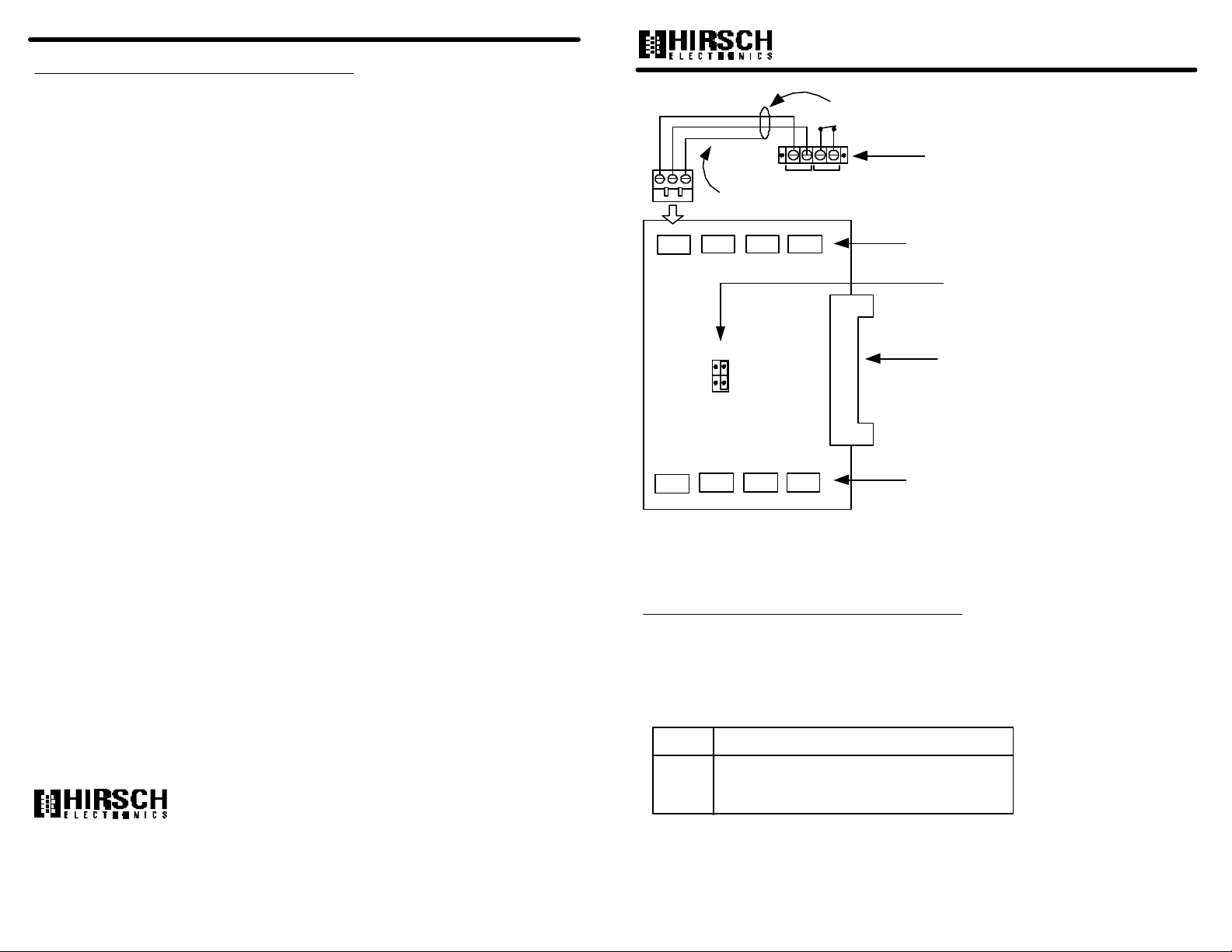
shield (terminate at controller only;
float at line module)
Line Module
HI LO 1
stranded, shielded
twisted pair
HI LO S HI LO S HI LO S HI LO S
XA1
XA2
Line Module
XA3
XA4
Alarm Input Connectors
(XA1 - XA4)
Address Jumpers
Expansion Board Interface
Cable Connector
(EBIC3 or EBIC5)
rev. 10/00
XA8
S
XA6
XA7
S S S
XA5
Alarm Input Connectors
(XA5 - XA8)
The AEB8 is an 8-input Alarm Expansion board where each input is supervised like the
inputs on the controller board. A Line Module is required for each input.
5. If the correct information doesn’t appear on the printouts, power down the
Controller and recheck the EBIC connections, then retry the test procedure. If
it still doesn’t work, contact Hirsch.
TM
1900 Carnegie Ave. Bldg. B
Santa Ana, CA 92705-5520
(949) 250-8888
www.hirschelectronics.com
Setup
No more than 2 AEB8s can be installed in the M2, M8, M64, MSP-8R, or MSP-64R.
The M16 cannot accommodate an AEB8.
There are two jumper positions in the middle of the board which control board
addressing:
Jumper Addresses
J1 1 - 8 (factory default for first AEB8)
J2 9 - 16 (default for second AEB8)

Mounting the Board
AEB8 Wiring
To mount the AEB8 expansion board:
1. Turn all system power off, remove connectors to the standby battery, then
remove connectors to the AC power.
2. If there is a SNIB board installed, remove it carefully.
3. Install the AEB8 board on the supplied standoffs.
If you are installing two AEB8s, it is recommended that you install the AEB8
set to J1 on top of the AEB8 set to J2.
4. After each board is installed, connect the appropriate EBIC5 connector.
5. If you have removed the SNIB board, reinstall it at the top of the card stack.
If a MEB/BE or MEB/CE board is installed, do not remove it. Removing
one of these boards will cause the controller to malfunction and requires
!
a system cold start. This will erase all additional information in memory
and requires complete system reprogramming.
connecting standoffs
to the board
To connect inputs to the AEB8:
1. If not already done, turn all system power off, remove connectors to the standby
battery, and remove connectors to the AC power.
2. Punch out the knockout in the controller enclosure where you plan to route the
wires. Either route these wires through the same opening you’re using for
controller board connections, or knock out a new opening for wires going to the
expansion boards.
3. Route the wires through the opening. If it makes wiring easier, detach each green
connector from the board as needed.
4. Loosen the screws on each connector plug you will be using.
5. Remove insulation from the wire and insert the specified wires into the green
connectors at the required slots.
6. Tighten the screws until the wire is securely fastened in the slot.
inserting wires into green
connectors
connecting additional
boards using standoffs
7. If you removed the green connector in step 3, push the green connector into the
appropriate socket until it locks into place.
The connector and socket are keyed, so there is only one way to plug it in.
reattaching the green
connectors to the board
 Loading...