

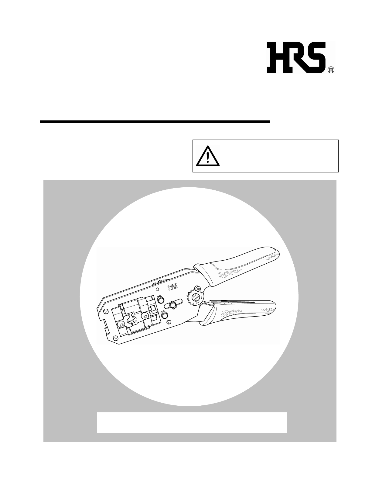
Hirose HT601/TM21P-88P Instruction Manual
MANUAL INSULATION
DISPLACEMENT TOOL
HT601/TM21P-88P
INSTRUCTION MANUAL
CAUTION :
Be sure to read this Instruction Manual carefully
before using it to secure safety in operation. In
addition, save this Instruction Manual so that it
is available whenever necessary for review.
ETAD
-
P0080 ATTACHED DOCUMENT 1
HIROSE ELECTRIC CO., LTD.

PREFACE
Congratulations on your purchase of Manual Tool, HT601/TM21P-88P for the modular plugs TM21P-88P and TM11P-88P.
This tool is the tool to perform the connection of TM21P-88P and TM11P-88P connectors.
Be sure to read this Instruction Manual carefully before using it to secure safety in operation.
- i -
FOR SAFE OPERATION
The operators of the tool and the maintenance personnel who are in charge of maintenance and repair work are required to read the
following SAFETY INSTRUCTIONS .
Fully understand and follow the descriptions given in this Instruction Manual and the warning symbols attached to the tool.
(I) Description of warning messages
* Determine the degree of impairment referring to the below-stated classification.
Major injur y : Loss of eyesight, wounds, burns (hyperthermal and hypothermal burns), electric shocks, fracture of a bone,
poisoning, etc. requiring emergency treatment or extended medical care.
Injury (Minor injury) : Wounds, burns, electric shocks, etc. requiring medical tr eatment.
Damage to pr operty : Damage to the machinery and or the surrounding area.
SAFETY INSTRUCTIONS
Basic safety instructions
1. Be sure to read understand and follow all the instructions and other materials supplied with the unit as before using the
tool. Save this Instruction Manual and make it available for review whenever necessar y.
Safe operation
1. Be sure to use the tool as instructed so that your fingers or are not part of clothing caught in the tool during crimping
operation.
Application
1. This tool shall only be used for its originally intended purpose while following the instructions specified in this
Instr uction Manual. Hirose assumes no responsibility for any misuse of the tool other than the intended use.
2. Modifications to this tool is prohibited. We assume no responsibility for accidents resulting from modifications.
Maintenance
1. To pr event possible accidents caused by unfamiliarity with the operation of the tool, repair and adjustment of the tool
shall be conducted only by maintenance personnel who have a full knowledge of the tool. Any repair and adjustment
beyond the range covered by the instr uctions given in this Instruction Manual is prohibited. We assume no
responsibility for accidents caused by improper repair or adjustment or the use of non-genuine par t(s).
2. To protect against personal injury, check to be sure that screws and nuts are properly tightened after the completion of
repair/adjustment works or replacement of the par ts.
3. Periodically cleaning of the tool is recommended.
4. In the event that your tool fails to perform normally after repair or adjusting immediately stop the work and contact us
for service so as to protect against personal injury.
Misuse of the tool will expose the operator to immediate danger of major injur y or
death.
WARNING
Misuse of the tool may expose the operator to danger of major injury or death.
Misuse of the tool may expose the operator to danger of injury and may cause
damage to property.
CAUTION
DANGER
CAUTION

CONTENTS
CHAPTER 1 SPECIFICATIONS AND CONFIGURATION....................................1
1-1. Model............................................................................................................................................1
1-2. Specifications................................................................................................................................1
1-3. Shape of tool and names of components......................................................................................2
CHAPTER 2 OPERATING PROCEDURE...................................................................3
2-1. Cable end finish............................................................................................................................3
2-2. Installing crimper and anvil ........................................................................................................7
2-3. Wire connecting operation...........................................................................................................8
2-4. Quality standard ..........................................................................................................................9
CHAPTER 3 MAINTENANCE AND INSPECTION .................................................10
3-1. Matters that demand special attention when handling.............................................................10
3-2. Daily maintenance......................................................................................................................10
- 1 -
CHAPTER 1 SPECIFICATIONS AND CONFIGURATION
1-1. Model
Product No.
HRS. No.
HT601/TM21P-88P
CL902-2133-1
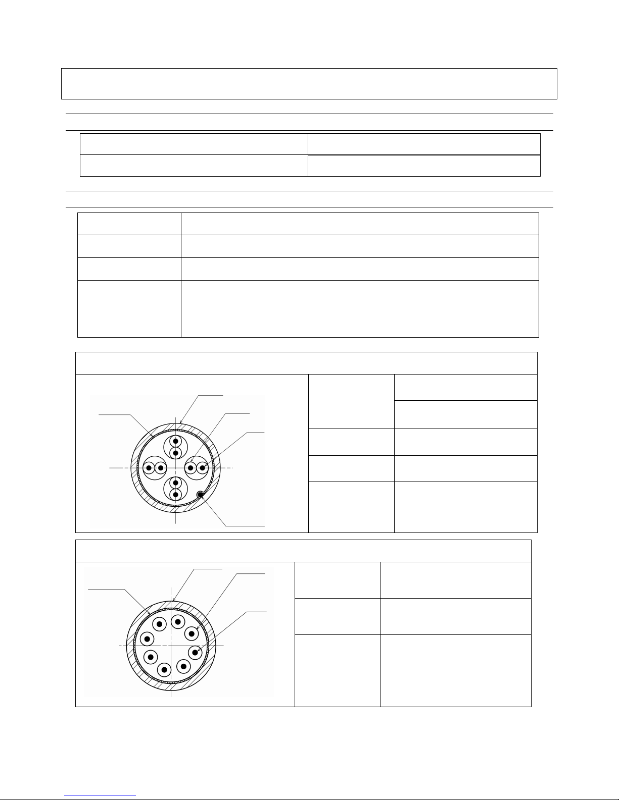
1-2. Specifications
Item Specification
External dimensions Length 222 mm X width 62 mm X thickness 21.5 mm
Weight 1.0 kg
Applicable plug
TM21P-88P (CL222-2862-9)
TM21CP-88P (CL222-2884-1-03)
TM21DP-TM-88P (CL222-2941-3)
TM11AP-88P (CL222-2780-6)
TM21P-88P applicable cable specifications
ø 0.5 mm solid wire
Conductor
AWG#24 stranded wire
(ø 0.2 mm X 7 wires)
Insulator external
diameter
(ø 0.9 ㎜ to φ 1.0 ㎜)
Drain wire AWG#26 (Tin plated wire)
Sheath external
diameter
(ø 6.6 ㎜)
TM11P-88P applicable cable specifications
Conductor
Equivalent to AWG#26
Insulator external
diameter
(ø 0.9 ㎜ to φ 1.0 ㎜)
Sheath external
diameter
(ø 5.0 ㎜)
Shield
Sheath
Insulator
Conductor
Drain wire
Shield
Insulator
Sheath
Conductor
 Loading...