

組立前に必ずこの説明書を最後まで、よくお読みにな
り、正しくお使い下さい。特に、「1.組立を始める前
に必ずお読み下さい」は、組立前及び飛行前に必ず読
んで下さい。
この説明書は、大切にお手元に保管して下さい。
製品改良のため、予告なく仕様を変更する場合があります。
Before assembly, completely read this instruction
manual. In particular, read the "1. Read before
assembly" section before assembly and operating the
unit.
Keep this instruction manual in a handy, safe place.
In order to make improvements to this product, the
specifications is subject to change without prior notice.
MADE IN JAPAN
C
2005
No.10A67
200mm
453mm
1,375mm
1,561mm
270mm
主要諸元
Main features
ギヤ比
Gear ratio
無線機
Radio control device
適合エンジン
Compatible engine
/60~70クラスエンジン 9.5 : 1 : 4.77
60~70 class engine
80~90クラスエンジン 7.9 : 1 : 4.77
80~90 class engine
/ ヘリ用プロポセット (別売)
Programmable transmitter set for model
helicopters (Sold separately)
/ 60~90クラス (別売)
60~90 class engine (Sold separately)
※(マフラー別売) (Muffler isn't included)

1
目 次
Table of Contents
このたびは、ヒロボー製品をお買上げいただき、ありがとうござい
ます。
安全にお使いいただくために、飛行前にこの取扱説明書を最後まで
よくお読みください。
飛行上の注意事項、本機の能力、飛行方法などを十分にご理解のう
え正しく、安全にルールやマナーを守って飛行くださるようお願いい
たします。
『シンボルとシグナル用語』の意味について
注意文の頭部に表示の「シンボルとシグナル用語」の意味を説明し
ます。
なお、 注意 に記載した事項でも、状況によっては重大な結果
に結びつく可能性があります。
(注):製品の組立、操作、メンテナンスに関する重要なご注意。
1. 組立る前に説明書を良く読んで、おおよその構造及び組立手順を理
解してから組立に入ってください。
2. 組立る前に、部品の数・内容をお確かめください。パック開封の後
は、部品の交換、返品等については応じかねます。万一部品の不足・
不良があった場合には、お手数ですが、愛用者カードに販売店の印
をもらい、ヒロボー株式会社・営業部まで、部品名と内容を明記の
上ご連絡ください。
Thank you very much for purchasing a Hirobo product. In order to be
able to use this product safely, please read this manual before flying the
helicopter. Please fly the helicopter safely observing all rules and
manners after having fully understood the flight precautions, the unit's
capabilities, and the best way to fly it.
The meaning of symbols and signal words
The meaning of symbols and signal words at the head of cautionary
notes are as explained below. Even comments marked with
may result in serious harm depending on the
circumstances.
Mishandling due to failure to follow
these instructions may result in severe
injury or death.
Mishandling due to failure to follow
these instructions may result in serious
harm.
Do not attempt under any circumstances.
(NOTE) : Implies important information regarding this product’s
assembly, operation, or maintenance.
1. Before assembly, read the instruction manual thoroughly familiarizing
yourself with the unit’s structure and assembly procedures.
2. Before assembly, check the quantity of parts and their descriptions.
After the packaging has been opened, parts cannot be exchanged or
returned. In the event of any missing or defective parts, have the
store from where you purchased the product stamp your user’s card
and send it with the name and description of the part(s) to Hirobo’s
Sales Department.
誤った取扱をしたときに、死亡や重傷等の重大な
結果に結び付く可能性が大きいもの。
誤った取扱をしたときに、状況によっては重大な
結果に結び付く可能性があるもの。
絶対に行わないでください。
組立を始める前に安全のために必ず
お守り下さい。
For safety reasons, observe the following
precautions before assembly.
WARNING
CAUTION
警告
注意
禁止
FORBIDDEN
1.組立を始める前に必ずお読み下さい
Read before assembly
CAUTION
1. 組立を始める前に必ずお読み下さい .................................. 1
・ネジの種類とサイズの見方............................................... 8
・キット以外に必要なもの................................................... 9
2. 組立編 ....................................................................................... 11
3. フライト編 ............................................................................... 46
4. メンテナンス編 ....................................................................... 56
5. 補修パーツについて ............................................................... 60
パーツリスト........................................................................... 61
データシート........................................................................... 73
1. Read before assembly............................................................... 1
· Screws and measurements...................................................... 8
· Necessary items not included in this kit ................................ 9
2. Assembly................................................................................... 11
3. Flight ......................................................................................... 46
4. Maintenance.............................................................................. 56
5. Parts for repair and maintenance.............................................. 60
Parts list..................................................................................... 61
Data sheet.................................................................................. 73

2
エンジン始動の前に Before starting the engine
1. 可能な限り、飛行場を清掃してください。
◆ 小石、ガラス、くぎ、針金、ひも、浮遊物等の異物を飛行場から
取り除いてください。
2. 周囲の状況を考慮してください。
◆ 強風、雨のとき、及び夜間は飛行させないでください。
◆ 人が多い場所では飛行させないでください。
◆ 家、学校、病院などの近くでは飛行させないでください。
◆ 道路、線路、電線などの近くでは飛行させないでください。
◆ 同じ周波数の無線操縦模型が近くにいる時は飛行させないでくだ
さい。
3. 次のような人、または状況下では飛行させないでください。
◆ 子供。
◆ 生理中、妊娠中の人。
◆ 疲れている時、病気の時、酔っている時。
◆ 薬物の影響、その他の理由で正常な操作ができない人。
◆ 初心者の方や、他人の機材を借りる場合、あらかじめ模型を良く
知っている人から安全指導を受けてから始めてください。
4. 無理して使用しないでください。
◆ 機能に適さない改造や加工をしないでください。
◆
使用限界が示されている物は、必ずその範囲で使用してください。
◆ 空中撮影や農薬散布には使用しないでください。
5. きちんとした服装ではじめてください。
◆ 長そで、長ズボンを着用してください。
◆
宝石や、物に引っ掛かりやすいものは、身につけないでください。
◆ 長い髪は、肩までの長さに結わえてください。
◆ 足下保護のため、必ず靴を着用してください。
◆ 高温部に触る場合等は、必要に応じて手袋をしてください。
6. ドライバーやレンチ等の工具は取り外してください。
◆ 始動する前に組立、取付、整備等に用いた工具類が取り外してあ
ることを確認してください。
7. 各部の点検をしてください。
◆ 始動前に、各部品に損傷がないか十分点検し、正常に作動する
か、また所定の機能を発揮するか確認してください。
◆ 可動部分の位置調整、及び各部のボルト、ナットの締付状態、部
品の損傷、取付状態、その他飛行に影響を及ぼす全ての箇所に異
常がないか確認してください。
◆ 無線機器の電源電圧(電池の量)は十分か確認してください。
◆ 損傷した部品、その他部品交換や修理は、説明書の指示に従って
ください。説明書に指示されていない場合は、お買上げ販売店、
またはヒロボー(株)営業本部エンジニアリングサービスで修理を
行なってください。
◆ 始動前に、必ず各部のネジがゆるんでいないか、指定部への給油
(オイル /グリス)、送・受信機用バッテリーが充分に充電されて
いるかを点検してください。
8. 純正部品を使用してください。
◆ 本説明書、及びヒロボーカタログに記載されている、純正部品以
外のものを使用しないでください。事故やけがの原因となる恐れ
があります。
9. エンジンを回さないで、各部の操作方法を練習してください。
◆
エンシンを始動させる前に、各部の操作方法を練習してください。
◆
操作を充分に修得するまではエンジンを始動させないでください。
◆ 機械の動きに異常がみられる場合もエンジンを始動させないでく
ださい。
1. Clear as much debris from the airfield as possible.
Clear away pebbles, glass, nails, wire, rope, floating objects, or other trash from
the airfield.
2. Consider the circumstances of the surrounding area.
Do not fly in strong winds, rain, or at night.
Do not fly in a crowded area.
Do not fly near homes, schools, or hospitals.
Do not fly near roads, railways, or power lines.
Do not fly near another radio controlled unit that uses the same frequency.
3. This unit must not be operated by:
Children.
Menstruating or pregnant women.
Tired, sick, or inebriated individuals.
Individuals under the influence of drugs or for some other reason incapable of
operating the unit normally.
Beginners or individuals operating a borrowed unit should proceed only after
having received safety instructions from someone familiar with the model.
4. Do not use the unit improperly.
Do not perform any remodeling or configuration unsuitable for the unit’s
functions.
Make sure to use within the range of the limitations indicated for the unit.
Do not use for aerial photography or crop dusting.
5. Wear appropriate clothing.
Wear a long-sleeve top and trousers.
Do not wear jewelry or objects that may get easily entangled.
Long hair should be bound to shoulder length.
Wear shoes for solid footing.
Wear gloves should it become necessary to touch hot components.
6. Put away screwdrivers, wrenches, or other tools.
Before starting the engine, check that any tools used in the assembly, installation,
or maintenance of the unit have been put away.
7. Inspect each part.
Before starting the engine, check for any damaged parts and make sure that the
unit operates normally with all its functions in order.
Adjust the positioning of moveable parts and check that all nuts and bolts are
fastened, that there are no damaged or improperly installed parts, and that there
are no abnormalities that would adversely affect the flight of the unit.
Check that the power supply voltage (charge of the batteries) in the remote control
is sufficient.
The exchange or repair of damaged parts should be performed according to the
instruction manual. In the event that the desired operation is not indicated in the
manual, ask for repair service at the store from where you purchased the product
or at the engineering services section of Hirobo’s Sales Department.
Before starting the engine, make sure that there are no loose screws, that all
specified locations are properly lubricated with grease or oil, and that the
transmitter and receiver batteries are properly charged.
8. Use genuine parts.
To reduce the risk of accidents and injuries, do not use parts other than those
shown in this instruction manual or in Hirobo catalogs.
9. With the engine off, practice how to operate each part.
Before starting the engine, practice how to operate each part.
Do not start the engine before having acquired sufficient handling skill.
Do not start the engine in the event that any abnormalities are noticed in the
movement of the mechanisms.
警告 WARNING
無線操縦エンジン模型の安全について
For the safe operation of radio controlled engines

3
警告 WARNING
燃料について Fuel
1. Only use GLOW fuel for model engines.
Gasoline or kerosene cannot be used.
GLOW fuel is highly volatile and flammable. Handle with care.
Use properly in accordance with the type of engine. (ABC or ring fitted)
2. If the engine uses gasoline, make sure to use a 1:25 mixture of 2-cycle
engine oil and gasoline.
3. Stop the engine and let it cool down sufficiently before refueling.
4. Do not refuel near a naked flame and especially not while smoking.
Refuel in a way as to prevent spilling and make sure to wipe up any
spilled fuel.
Because fuel vapors and exhaust gas are hazardous, make sure to use the
product outdoors.
To reduce the risk of explosions, do not incinerate empty fuel cans.
5. It is harmful to drink the fuel or get it in the eyes.
In the event of an accident, induce vomiting or thoroughly wash out the
eyes and see a doctor immediately.
6. After refueling, start the engine at a distance of 3m or more away from
where the refueling took place.
7. Fasten the fuel can cap tightly and keep it in a cool, dark place out of the
reach of children.
1. 模型用エンジンは模型専用のグロー燃料が必要です。
◆ ガソリンや灯油は使用できません。
◆ グロー燃料は揮発性が高く引火しやすいので取り扱いには十分注
意してください。
◆ エンジンのタイプ(ABC又はリング付/用途別)により使い分けを
してください。
2.
ガソリンエンジンの場合は、ガソリン25に対し2サイクルエンジンオ
イル1 の割合で混合させたものを、必ず使用してください。
3. 燃料を補給するときは、必ずエンジンを停止させて、十分冷えてか
ら行なってください。
4. 火気の近くでは、絶対に燃料補給しないでください。特にタバコを
吸いながらの作業は行なわないでください。
◆ 燃料はこぼさないように補給し、こぼれた時は必ず拭き取ってく
ださい。
◆ 燃料の蒸気、排気ガスは有害ですので、必ず屋外で取り扱ってく
ださい。
◆
空缶は火中には投入しないでください。爆発の恐れがあります。
5. 燃料は間違えて、飲んだり目に入ると有害です。
◆ 万一事故が起きた場合には、吐かせる、洗眼するなどをした後す
ぐに医師の診察をうけてください。
6. 給油後は、給油場所から3m 以上離れて、エンジンを始動してくだ
さい。
7. 燃料はキャップをしっかりしめ、幼児の手の届かない冷暗所に保管
してください。
飛行中は While in flight
1. 無理な姿勢で操縦しないでください。
◆ 寝転んだり、座り込んだりした姿勢で操縦しないでください。
◆ 傾斜地は、滑りやすいので足下に十分注意してください。
2. 次の場合は、エンジンを停止させてください。
◆ 機体の調整および、送信機の調整を行なうとき。
◆ 付属品および部品を交換するとき。
◆ 機体の調子が悪かったり、異常音や異常振動を発生したとき。
◆ その他危険が予想されるとき。
3. エンジンを始動するときは、次のことに注意してください。
◆ 周囲に人、動物、障害物がないか十分に確認してから始動して
ください。
◆ しっかりと機体を固定または保持してください。
◆ 送信機のスロットルのスティック位置及び、エンジンのキャブ
レター開度が、最スローの位置(アイドリング状態)にあることを
確認してください。
4. 怪我の恐れがありますので回転部分に手や物を入れないでくださ
い。
5. 飛行はゆとりとマナーを守ってお楽しみください。
◆ 一度に長時間の操縦や、連続して長時間の操縦は、疲労により
判断力を鈍らせ、思わぬ事故の原因となりますので、適当に休
憩を取るようにしてください。
◆ 操縦しているときは、あまり機体に近づかないでください。
◆ 本人の技量にあった飛行をしてください。無理な飛行は思わぬ
事故や怪我につながります。
6. エンジン始動後はもとより停止直後は、マフラーやエンジン本体は
高温になっております。火傷防止のためマフラーやエンジンに降れ
ないようにしてください。
1. Do not operate in an awkward posture.
Do not operate seated or lying down.
Because slopes are slippery, exercise caution so as to not loose your
footing.
2. Stop the engine in the following situations:
When adjusting the unit’s body or the transmitter.
When replacing accessories or parts.
When the body of the unit is out of alignment or when abnormal noises
or vibrations occur.
Whenever some kind of danger is anticipated.
3. Exercise the following precautions when starting the engine.
Check that there are no people, animals, or obstructions in the surrounding
area.
Hold the unit securely.
Check that the position of the transmitter’s throttle stick and the engine
carburetor are at their lowest positions (idling).
4. To reduce the risk of injury, do not insert hands or objects in rotating parts.
5. Enjoy the flight while observing safety rules and manners.
Fatigue brought upon by continuous operation for long periods at a time
may result in impaired judgment or accidents. Be sure to take sufficient
rests.
When operating, do not get too close to the unit.
Operate the unit within the limits of your ability. Operating the unit
improperly increases the risk of accidents or injury.
6. The engine and muffler become very hot after starting the engine and remain
hot immediately after shutdown. To prevent burns, do not touch the engine
or muffler.

4
警 告 WARNING
1. 注意深く点検をしてください。
◆ すぐに各部の点検を行ない、ネジのゆるみや脱落があれば必ず補
修してください。
◆ 油、よごれ、水滴等はすぐに拭き取ってください。
◆ 長時間保管する場合には燃料タンク、キャブレター内の燃料をす
べて抜き取ってください。
◆ 注油や部品の交換は、説明書に従ってください。
2. きちんと保管してください。
◆ 乾燥した場所で、幼児の手の届かないところに保管してくださ
い。
3. 修理は、お買上げの販売店、またはヒロボー(株)営業本部エンジニ
アリングサービスにお申し付けください。
◆ 修理の知識のない方や専用工具を持っていない方が修理をする
と、十分な性能を発揮しないだけでなく、事故や怪我の原因とな
ります。
◆ 修理、調整をするときは、エンジンを停止して行なってくださ
い。
◆ 損傷、故障箇所がある場合には、修理してから保管してくださ
い。この場合、部品は、指定の純正部品を必ず使用してください。
◆ 本体及び周辺機器の加工や改造は、本来の性能を発揮できなくな
る場合がありますので行なわないでください。
◆ 保管時や輸送時は、燃料の損失、破損や怪我を防ぐため、機体を
しっかりと固定してください。
騒音について
飛行に際し、周囲に迷惑をかけないように十分に消音効果のあるマフ
ラー(サイレンサー)を必ず装着してください。
1. Conduct a thorough inspection.
Immediately inspect each part and retighten or replace any screws that
may have become loose or fallen out.
Wipe away any oil, dirt, or water.
If storing for an extended period of time, completely remove the fuel
from the tank and carburetor.
Lubricate or replace parts according to the instruction manual.
2. Store the unit properly.
Store in a dry place out of the reach of children.
3. Inquire about repairs at the store from where you purchased the product or
at the engineering services section of Hirobo’s Sales Department.
Individuals lacking proper knowledge or tools necessary for repairs may
not only impair the performance of the unit but may also increase the
risk of accidents or injury.
Turn off the engine before performing any repairs or adjustments.
Repair all damaged parts before storage. Make sure to use only
designated, genuine parts.
Do not perform any remodeling or reconfiguration of the unit’ s body or
peripheral equipment. Doing so may impair the unit’s performance.
When storing or transporting the unit, secure it firmly so as to prevent
fuel loss, damage, or injury.
Noise
When flying the unit be sure have the muffler (silencer) attached in order to
avoid disturbing people in the surrounding area.
飛行後は After a flight

5
警告 WARNING
無線操縦ヘリコプターを安全に
お取り扱いいただくために
先に、無線操縦エンジン模型として共通の注意事項を述べましたが、ヘ
リコプターの場合、さらに次に述べる注意事項を守ってください。
実機の場合、飛行前には厳しい点検が義務付けられています。無線操
縦(R/C)ヘリコプターは小型で手軽に飛行させることができますが、空
を飛ぶことは実機と何ら変わりがありません。万一、人や車などにぶ
つかれば、大けがや破損につながり、多大な迷惑を与えます。
飛行中の事故は操縦者が責任者扱いされる場合がありますので、必ず
ラジコン保険に加入してください。詳しくは本機をお買い求めになっ
た販売店へお問合せください。
飛行の前や異常が発生した時には、必ず点検をしてください。飛行中
に、ローターブレードで地面をたたいた場合、何も損傷がないようで
も、各部に微細な亀裂やゆるみが発生していることがあります。その
ままで飛行していると、ローターの亀裂が大きくなり、毎分1200〜2000
回前後の高速回転をしているローターの内部からウエイトが飛び出し
たり、ローターがブレードホルダーから抜けたりする大事故になりま
す。
少しでも疑わしい状態が発生したら、すぐに部品交換をしてください。
部品は必ず純正部品を使用してください。
1. 初心者の方は、指導できる方から安全及び技術指導を受けてくださ
い。独学は非常に危険です。
2. 各部のナットやボルトにゆるみ、脱落がないか確認してください。
3. リンケージのロッドやアジャスターにガタやゆるみがないか確認し
てください。
4. エンジンマウントのボルトにゆるみがないか確認してください。
5. ローターブレードに傷や亀裂がないか、ブレードホルダー周辺は入
念に確認してください。
6. ローターブレードのウエイトは安全に固定されているか確認してく
ださい。
7. 送信機、受信機、スターター、プラグヒート用のバッテリー容量は
十分か確認してください。
8. 燃料及び配管の状態を確認してください。燃料チューブの折れ曲が
りやフィルターの目づまり、又、特に古くなった燃料等は始動性が
悪いばかりではなく、飛行中のエンジン停止から墜落事故につなが
る場合があります。
9. グロープラグの状態を確認してください。特に古くなったプラグは
始動性が悪いばかりではなく、飛行中のエンジン停止から墜落事故
につながる場合があります。
10. 電波の届く距離を確認してください。
11. 全てのサーボがスムーズに動作するか確認してください。誤動作や
ムリな動作は操縦不能の原因となり、たいへん危険です。
12. ジャイロは正しく作動するか確認してください。特に初期状態にお
いては動作方向を確認してください。
13. テールローターの駆動ベルトのテンションは適当か確認してくださ
い。
14. 機体各部の潤滑油の給油を確認してください。
In addition to the standard precautions previously mentioned regarding radio
controlled engines, please observe also the following precautionary items which
are specific to helicopters.
For real aircraft, strict pre-flight inspections are mandatory. The radio controlled
helicopter when in flight is essentially no different from a real aircraft even
though it is small and can be flown easily. It may be a great nuisance to others
and, should it strike a person or vehicle, may cause severe injury or damage.
The operator of a radio controlled unit may be held liable for accidents occurring
during flight. For this reason, inquire at the store of purchase about special
insurance that may be taken out for radio controlled devices.
Make sure to inspect the unit thoroughly before flight and in the case of any
abnormality. If the rotor blades should strike the ground during flight, there
may be tiny cracks or loosening in various places even though there may not be
any visible damage. If flown in this condition, the cracks may increase in size
and cause severe accidents such as the weight flying off from the rotor’s interior
or the rotor itself, which spins at a speed of 1200~2000 rpm, may fly off from
the blade holder.
If in doubt about the condition of any part, replace it immediately using only
genuine parts.
1. Beginners should have safety and technical guidance from an experienced
individual. Teaching yourself is extremely dangerous.
2. Check that there are no missing or loose nuts or bolts.
3. Check that there is no rattle or loosening in the linkage rods or adjusters.
4. Check that there are no loose bolts in the engine mount.
5. Carefully check that the rotor blades are not damaged or cracked, especially
in the vicinity of the blade holder.
6. Check that the rotor blade weight is safely fastened.
7. Check that the batteries for the transmitter, receiver, starter, and the plug
heat are sufficiently charged.
8. Check the condition of the fuel and fuel line. Bent tubes, clogged filters,
and especially old fuel may not only render the engine difficult to start but
may also cause it to stall mid-flight resulting in crashes.
9. Check the condition of the glow plugs. Old plugs may not only render the
engine difficult to start but may also cause it to stall mid-flight resulting in
crashes.
10. Check the reach of the radio waves.
11. Check that the servos operate smoothly. Their malfunction may cause a
loss of control and increase the risk of danger.
12. Check that the gyro is operating properly and, especially, in the right
direction while starting the engine.
13. Check the tension of the tail rotor belt drive.
14. Check that each part of the unit’s body is sufficiently lubricated.
フライト前の始業点検 Pre-flight inspection
For safe handling of the radio controlled helicopter

6
警告 WARNING
注 意 CAUTION
フライト中の安全確認 In-flight safety check
保管場所 Storage area
フライト後の安全点検 After-flight safety inspection
1. エンジンを始動するときは周辺に当たるものや、巻き込まれそうな
ものがないか確認してください。
2. 周囲に同じ周波数の使用者がいないことを確認して、送信機→受信
機の順番にスイッチを入れ、送信機のスロットルスティック及びト
リムをエンシン始動の位置にセットしてください。このとき送信機
によっては、アイドルアップ/スロットルホールド / フライトモー
ド等のスイッチ位置によりキャブレターの開度がエンジン始動位置
にいない場合がありますので、必ず始動位置に戻してください。
3. エンジン始動には、必ずローターヘッドをしっかりと回転しないよ
うに手で押さえてください。
4. エンジン始動後は、エンジン及びマフラー部が高温になりますの
で、火傷に注意してください。
5. 飛行をはじめるヘリコプターの位置は、エンジン始動位置および、
操縦者より15m 以上離れた場所で行なってください。また、周囲
の状況を十分把握し、飛行場内に他の人や危険物、障害物がないか
確認してください。
6. 機体が浮かび上がる直前に、トラッキング(各ローターの軌跡)調整
を行なってください。トラッキングを確認する場合でも、機体から
5m 以内に近づかないでください。
7. 飛行中に異常な振動や、異常な音が発生した場合、すぐに着陸さ
せ、エンジンを停止させ原因を確認してください。
8. 無理な飛行や無謀な操縦は、事故や怪我の原因となりますので、
ルールやマナーを守り、安全に責任をもってお楽しみください。
1. 飛行が終わったら、すぐに各部の点検を行ってください。ネジのゆ
るみや脱落があれば、必ず補修してください。各部に傷や破損があ
れば、交換してください。
2. 油汚れ等をきれいに拭き取ってください。
3. 長時間(期間)飛行させない場合は、燃料タンク及びキャブレター内
の燃料を抜き取ってください。
1. 直射日光のあたる場所、高温になる場所(車内等)に放置しないでく
ださい。
必ず風通しのよい日陰で保管してください。
2. タンクに燃料を補給したままヘリコプターを保管しないでくださ
い。
1. エンジン始動後は、必ず送信機のスロットルトリム最スローの位
置でエンジン停止が行なえることを確認してください。
2. エンジンのスロー絞りの調整をアイドリング中に行なう場合は、
必ずローターヘッドが回転しないようにしっかりと押さえて、行
なってください。また、排気ガスには十分注意してください。
1. Check that there are no objects in the surrounding area that may get
entangled or struck by the unit.
2. Check that there are no other operators in the surrounding area using the
same frequency and, after turning on first the transmitter and then the
receiver consecutively, set the transmitter’s throttle stick and trim to their
engine start-up positions. Depending on the transmitter unit, the carburetor
may not be in its engine start-up position due to the positioning of the idleup, throttle-hold, or flight-mode switches. Make sure to return them to
their start-up positions.
3. When starting the engine, make sure to hold the rotor head firmly by hand
so as to not let it rotate.
4. Because the engine and muffler become hot immediately after the engine
is started, exercise caution so as to prevent burns.
5. When taking off, the unit should be positioned 15 meters or more away
from the operator . Be aware of the conditions of the surrounding area and
check that there are no other people or dangerous obstacles.
6. Just before take off, adjust the tracking (each rotor’s track). Even when
checking the tracking, do not get nearer than 5 meters from the unit.
7. In the event that abnormal noises or vibrations should occur, land the unit
immediately, stop the engine, and check the cause of the problem.
8. Because operating the unit improperly or recklessly may cause accidents
or injury, observe all safety rules and manners and enjoy operating the unit
safely and responsibly.
1. Immediately inspect each part after every flight. Be sure to replace or
retighten missing or loose screws and replace any damaged parts.
2. Wipe away any oil or dirt.
3. If the unit will not be flown for a long period of time, empty the fuel from
the tank and carburetor.
1. Do not store in an area exposed to direct sunlight or where temperatures
may rise (i.e. in a car). Instead, store it in a shaded, well ventilated area.
2. Do not store the unit with fuel in its tank.
1. After starting the engine, check if the engine stalls when the transmitter’s
throttle trim is at its lowest position.
2. When adjusting the engine’s low throttle speed while idling, be sure to
hold down the rotor head firmly so as to prevent it from rotating. Be
careful of exhaust fumes.

7
スワッシュプレート部の組立
Swash plate assembly
9
ピボットボルトがスワッシュプレートに締め込みにくい場合は、
はじめにM3CS等のネジを使い、ネジ山を切っておくと、締め
込み易くなります。
If the pivot bolts are difficult to fasten on the swash plate,
use a 3mm screw and cut threads in the holes beforehand
to make the fastening of the bolts easier.
注 意 Caution
ピボットボルト(D) ............. 3
Pivot bolt (D)
ピボットボルト(E) ............. 4
Pivot bolt (E)
ピボ ットボルト(E)
Pivot bolt (E)
ピボ ットボルト(D)
Pivot bolt (D)
ピボ ットボルト(E)
Pivot bolt (E)
ピボ ットボルト(E)
Pivot bolt (E)
ピボ ットボルト(D)
Pivot bolt (D)
ピボ ットボルト(D)
Pivot bolt (D)
スワッシュプレート
Swash plate
Due to a lack of proper testing, please acknowledge that Hirobo
will not take responsibility for accidents resulting from
remodeling the unit or from the replacement of parts with those
not manufactured by Hirobo.
本製品の改造、又、弊社以外の部品交換について、十分なテストを
行っていませんので、事故発生の可能性もあります。その場合、一
切の責任を負いかねますのでご了承ください。
この説明書の見方 How to use this instruction manual
組立前の注意
Pre-assembly precautions
警告
W ARNING
1
1. 組立る前に説明書を良く読んで、おおよその構造及び組立手順を理
解してから組立に入ってください。正しい組立を行わないと、本来
の性能を発揮できなくなるばかりでなく、大変危険です。
2. 組立てる前に、部品の数・内容をお確かめください。パック開封
の後は、部品の交換、返品等については応じかねます。万一部品の
不足・不良があった場合には、お手数ですが、愛用者カードに販
売店の印をもらい、ヒロボー株式会社・営業本部まで、部品名と
内容を明記の上ご連絡ください。
①
Lock
のマークがある箇所は、ホビータイト(ネジロック剤)を
使用してください。
② 説明書の左欄を参考にして、小物類の数量チェックを行ってくださ
い。
1. Before assembly, read the instruction manual thoroughly and familiarize
yourself with the unit’s structure and assembly procedures. Failure to
assemble the unit properly may not only result in impaired performance
but may also increase the risk of danger.
2. Before assembly, check the quantity of parts and their descriptions. After
the packaging has been opened, parts cannot be exchanged or returned. In
the event of any missing or defective parts, have the store from where you
purchased the product stamp your user’s card and send it with the name
and description of the part(s) to Hirobo’s Sales Department.
① Apply Hobby Tight (thread locking agent) at each location indicated with
Lock
.
② In the instruction manual, refer to the column on the left-hand side to check
the type and quantity of small parts.
小物部品の名前、原寸図、使用数
Part name, full-scale illustration, and quantity.
2

8
本説明書の文中に記載している記号は、次の約束になっています。
● 単位はミリメートルです。以下、文中で長さなどに表示されてい
る単位はミリメートルです。
ネジの種類とサイズの見方
How to read part types and sizes
The symbols shown in this instruction manual are shown as below:
The unit of measurement is the millimeter. The lengths, etc. shown
in the following are indicated in
millimeters.
タッピングビスは、部品にネジを切りながらしめつけるビスです。しめこ
みが固い場合がありますが、部品が確実に固定されるまでしめこんでくだ
さい。ただし、しめすぎるとネジがきかなくなりますので、部品が変形す
るまでしめないでください。
Tapping screws cut threads in the holes of the parts. When screws are difficult to
tighten, fasten the screw until the part is properly set. However, do not over-tighten
the screw to the point of stripping the threads or warping the part.
セットスクリュー
Set screw
M3X4SS
段付ビス
Shoulder screw
M2X4.5段付
M2X4.5
shoulder screw
タッピングビス1種
Tapping screw 1
M3X10TS-1
タッピングビス2種
Tapping screw 2
M3X8TS-2
皿ビス
Countersunk screw
M3X12皿ビス
M3X12
countersunk screw
皿タッピングビス
Countersunk tapping
screw
M3X10皿TS-1
M3X10
countersunk TS-1
フラットワッシャー
Flat washer
ベアリング
Bearing
Brg. ø4Xø8X4ZZ
Brg. ø4Xø8X2.5F ZZ
FW 3X9X1T
ナット
Nut
M3 ナット
M3 nut
ø5ボール
ø5 ball
ø5ボール
ø5 ball
ナイロンナット
Nylon nut
Grooved
M3 ナイロンナット
M3 nylon nut
Eリング
E-ring
ø6 Eリング
ø6 e-ring
メタル
Bushing
Collar 3X6X7
カラー3X6X7
キャップスクリュー
Cap screw
M3X8CS
ナベ頭ビス
Pan-head screw
M3X12PH
3mm
5.5mm
3mm
3mm
8mm
6mm
3mm
9mm
1mm
3mm
4mm
3mm
12mm
カラー
Collar
Collar 5X8X5.5
カラー5X8X5.5
スラストベアリング
Thrust bearing
Brg. ø6Xø12X4.5H
ボタンボルト
Button bolt
M3X8ボタンボルト
M3X8 button bolt
3mm
10mm
3mm
ミゾ付
8mm
3mm
12mm
3mm
10mm
2mm
4.5mm
4mm
4mm
8mm
4mm
2.5mm
8mm
5mm
3mm
7mm
6mm
5.5mm
8mm
5mm
12mm
6mm
4.5mm
3mm
8mm
しめすぎ
Over-tightened.
ネジがきかない
Stripped threads.
Correct
Wrong

9
当機を楽しむためには、以下のものが必要です。(別売)
フライトするためにキット以外に必要なもの
(別売)
The following items are necessary in order to use the unit. (sold separately)
Items necessary for flying this model not
included in this kit (Sold separately)
エンジンスターター用
バッテリー12V
12V engine
starter battery
ヒロボーRC燃料
HIROBO RC Fuel For Helicopter & Airplane
15% ニトロメタン(オイル約20%)
15%Nitromethan (approx.20%oil)
2515-200 ¥4,200 (4,000)
23% ニトロメタン(オイル約20%)
23%Nitromethan (approx.20%oil)
2515-201 ¥5,250 (5,000)
30% ニトロメタン(オイル約20%)
30%Nitromethan (approx.20%oil)
2515-202 ¥6,300 (6,000)
30% ニトロメタンF3Cコンテスト(オイル量約10%、低オイル仕様)
30%Nitromethan F3C Contest (approx.10% oil, low oil specification)
2515-203 ¥6,300 (6,000)
エンジンプラグヒート用
バッテリー
Engine plug heating
battery
2401-011 ¥1,470 (1,400)
グロープラグコード
Booster cables
エンジン始動用スターター
Engine starter
2513-072 ¥525 (500)
2513-038 ¥315 (300)
2513-070 ¥9,240 (8,800)
燃料ポンプ
Fuel pump
ホビーオイル
Hobby oil
ピッチゲージ
Pitch gauge
マフラー
Muffler
2513-040
¥2,940 (2,800)
2513-066 ¥1,050 (1,000)
2513-053
¥3,990 (3,800)
2515-003
¥315 (300)
スターターシャフト
(ワンウェイ
ベアリング入り)
Starter shaft
(With one-way
bearing)
シリコンパイプ
2.5X5X1000
Silicon pipe
燃料フィルター
Fuel filter
エンジン60〜90クラス
Engine 60-90 class
¥税込価格(税抜価格)
* The prices in parentheses are the prices excluding consumption tax.
ハサミ
Scissors
ピンドライバー
Pin driver
ロッドエンドペンチ
Rod-end (ball link)
pliers
ネジロック剤
Thread locking
agent
ロッドエンドドライバー
Rod-end (ball link) driver
2513-041
¥3,675 (3,500)
2513-024
¥630 (600)
2513-042
¥840 (800)
ø1.2, ø1.8, ø2.0
六角レンチ
Allen hex socket driver
瞬間接着剤
Instant adhesive
2513-045 ¥840 (800)
(曲面/Curve)
2513-046 ¥630 (600)
(ミニ/Mini)
エポキシ接着剤
Epoxy adhesive
1.5mm2513-054¥945 (900)
2mm 2513-055¥945 (900)
2.5mm2513-056¥945 (900)
3mm 2513-057¥945 (900)
十字レンチ
Cross wrench
2513-044
¥315 (300)
+ドライバー 大・小
Large and small
Phillips screwdrivers
ラジオペンチ
Long-nose pliers
カッターナイフ
Cutter knife
ニッパー
Nipper
モリブデングリス
Molybdenum grease
2515-127
¥1,050 (1,000)
¥税込価格(税抜価格)
* The prices in parentheses are the prices excluding consumption tax.
送信機
Transmitter
0414-159 ¥21,000 (20,000)
プロポセット
Radio set
受信機
Receiver
エルロンサーボ
Aileron servo
エレベーターサーボ
Elevator servo
ピッチサーボ
Pitch servo
スロットルサーボ
Throttle servo
スイッチ
Switch
Ni-Cdバッテリー
Nickel-cadmium battery
ラダーサーボ
Rudder servo
コントロールアンプ
Control amplifier
フィルター付
延長コード
Extension
cord with
filter
ジャイロ
Gyro
Tools necessary for assembly
組立に必要な工具

10
Useful tools
あると便利な周辺用具
RC メカクッションパッド
RC mechanical cushion pad
2513-052 ( ピンク/Pink) ¥525 (500)
2513-062 ( キイロ/Yellow) ¥525 (500)
フライホイールレンチ
Fly wheel wrench
2513-035 ¥1,029 (980)
プラグレンチ
Plug wrench
2513-025
¥2,625 (2,500)
2513-026
¥1,050 (1,000)
プーラー
Puller
2513-034 ¥1,890 (1,800)
バッテリーチェッカー
Battery checker
2410-003 ¥3,465 (3,300)
¥税込価格(税抜価格)
コード 備 考
Code
Unit price in yen
品 名
Name
Remarks
2515-219
RCグラスター
R/C Glaster
汚れの除去とつや出しが一度にできるワックス入りクリーナー
A cleaner that includes wax that lets you wash off the dirt and polish all at once
2515-119
RC脱脂クリーナー
R/C Degreasing Cleaner
グローエンジン内部及びシリコン部品の洗浄には使用出来ません
Cannot be used inside the glow engine or on silicon components.
2515-120
RCアルコールスプレー
R/C Alcohol Spray
グローエンジン内部及びシリコン部品にも使用出来ます(飲用不可)
Can be used inside the glow engine and on silicon components. (Not fit for drinking.)
2515-121
RCほこりとばしスプレー
R/C Dust Blower Spray
強力エアーでほこりを一発除去
A strong jet of air that blows away dust in a single shot.
2515-122
RC冷却スプレー
R/C Cooling Spray
瞬間的にマイナス温度に冷却、エンジンのオーバーヒート、ニッカドバッテリーの急速冷却に有効
Cools down to below zero in just a few seconds. Perfect for the quick cooling of overheated
engines or Ni-Cd batteries.
2515-123
RCグリススプレー
R/C Grease Spray
たれ落ちないグリス、垂直面にもOK!
Grease that doesn't drip. Great for vertical surfaces too!
2515-124
RC防錆潤滑スプレー
R/C Anti-rust Lubricating
Spray
さらっとした防錆潤滑剤
Anti-rust lubricant that leaves the surface smooth and not greasy.
945
(900)
1,050
(1,000)
1,260
(1,200)
1,890
(1,800)
1,890
(1,800)
840
(800)
840
(800)
税込価格
(税抜価格)円
* The prices in parentheses are the prices excluding consumption tax.
* The prices in parentheses are the prices excluding consumption tax.
ブレードサポート
Blade support
2513-039 ¥525 (500)
各部の名称
Names of each component
メインブレード
Main blade
スタビライザーブレード
Stabilizer blade
テールブレード
Tail blade
メインローターヘッド
Main rotor head
キャビン
Cabin
テールブームブレース
Tail boom brace
水平尾翼
Horizontal tail fin
(stabilizer)
垂直尾翼
Vertical tail fin
(stabilizer)
テールブーム
Tail boom
11
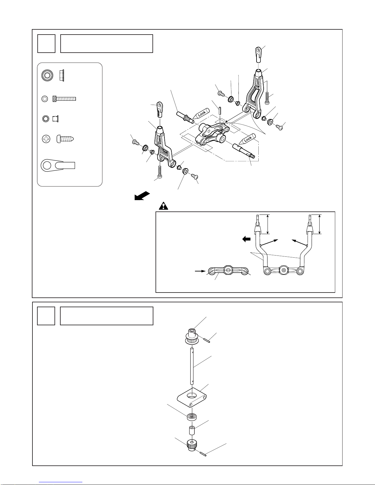
エレベーターレバーの組立
Elevator lever assembly
1
2. 組立編 Assembly
カウンターギヤ部の組立
Counter gear assembly
2
テールプーリー18T
Tail pulley 18T
ø2X12ロールピン
ø2X12 roll pin
ø2X12ロールピン
ø2X12 roll pin
C ø5Xø6.5X14
カウンターギヤシャフ
ト
Counter gear shaft
カウンターギヤ18T
Counter gear 18T
Brg. ø5X13X4ZZ
SF Brg.ホルダー ø13
SF bearing holder ø13
カウンターギヤAssy工場組立済
Counter gear assembly
(pre-assembled)
Brg. ø3Xø6X2.5FZZ ............ 4
M2X12CS............................. 2
C ø2.6Xø3X3.4F .................. 4
M2.6X8TS-2......................... 4
M2.6X8TS-2
M2ロッドエンド................. 2
M2 rod end
注意 Caution
(L)側から見た図
View from the left side
エレベーターアームおよびエレ
ベーターレバーの向きに注意し
てください。
Note the direction of the
elevator arm and the elevator
lever.
M2ロッドエンド
M2 rod end
M2ロッドエンド
M2 rod end
ミゾを合わせます。
前
Front
エレベーターレバーシャフト(L)
Elevator lever shaft (L)
エレベーターレバーAssy工場組立済
Elevator lever assembly (pre-assembled)
エレベーターレバーシャフト(R)
Elevator lever shaft (R)
エレベーターアーム
Elevator arm
エレベーターアーム
Elevator arm
M2.6X8TS-2
M2.6X8TS-2
M2.6X8TS-2
M2.6X8TS-2
M2X12CS
M2X12CS
Brg. ø3Xø6X2.5FZZ
Brg. ø3Xø6X2.5FZZ
Brg. ø3Xø6X2.5FZZ
Brg. ø3Xø6X2.5FZZ
ロールピンø2X10
Roll pin ø2X10
C ø2.6Xø3X3.4F
C ø2.6Xø3X3.4F
C ø2.6Xø3X3.4F
C ø2.6Xø3X3.4F
前
下向きに下がる
Pointing down
エレベーターレバー
Elevator lever
エレベーターアーム
Elevator arm
Front
23mm
内側
Inside
23mm
12
キャビンクロスメンバー L34.5
Cabin cross member L34.5
キャビンクロスメンバー L34.5
Cabin cross member L34.5
六角クロスメンバー M3X46
Hexagonal cross member M3X46
六角クロスメンバー M3X46
Hexagonal cross member M3X46
クロスメンバー M3X26
Cross member M3X26
エレベーターレバーAssy
Elevator lever assembly
カウンターギヤAssy
Counter gear assembly
左側
Left
キャビンクロスメンバー L43
Cabin cross member L43
キャビンクロスメンバー L43
Cabin cross member L43
M3X12CS
M3X12CS
M3X12CS
M3X8CS
M3X8CS
M3X12CS
Brg. ø8Xø16X5ZZ
Brg. ø8Xø16X5ZZ
Brg. ø10Xø19X5ZZ
Brg. ø6Xø19X6ZZ
Brg. ø10Xø19X5ZZ
Brg. ø5Xø13X4ZZ
FW ø5Xø7X0.1(調整用)
(for adjustment)
キャビンクロスメンバー L24
Cabin cross member L24
M3X12CS
M3X12CS
防振ゴム
Rubber insulator
キャビンクロスメンバー L24
Cabin cross member L24
防振ゴム
Rubber insulator
キャビンクロスメンバー L24
Cabin cross member L24
防振ゴム
Rubber insulator
サーボ フレーム (L)
Servo frame (Left)
サーボ フレーム (R)
Servo frame (Right)
瞬間接着剤
Instant adhesive
ポイント
Point
軸方向のあそびが多い場合に使用して下さい。
入れすぎると回転が重くなります。
Use included ø5Xø7X0.1 shims to remove any end
play in the counter gear assembly. If too many shims
are used, this will cause bind age in the assembly.
サーボフレームの組立 -1
Servo frame assembly
3
キャビンクロスメンバーL43 ................
2
Cabin cross member L43
キャビンクロスメンバーL34.5 .............
2
Cabin cross member L34.5
キャビンクロスメンバーL24 ................
2
Cabin cross member L24
クロスメンバーM3X26 ...... 1
Cross member M3X26
六角クロスメンバーM3X46 ..........
7
Hexagonal cross member M3X46
M3X8CS ............................... 2
M3X12CS ............................. 6
防振ゴム .............................. 2
Rubber insulator
エレベーターレバーAssy の向きに注意してください。
Note the direction of the elevator lever assembly.
注意 Caution
Brg. ø5Xø13X4ZZ................ 1
Brg. ø8Xø16X5ZZ................ 2
Brg. ø6Xø19X6ZZ................ 1
Brg. ø10Xø19X5ZZ.............. 4
キャビンクロスメンバー L24に防振ゴムを瞬間接着剤
等で接着します。
Use instant adhesive to attach rubber isolators to the L=24
cabin cross members.
FW ø5Xø7X0.1 .................... 2
(調整用)(for adjustment)
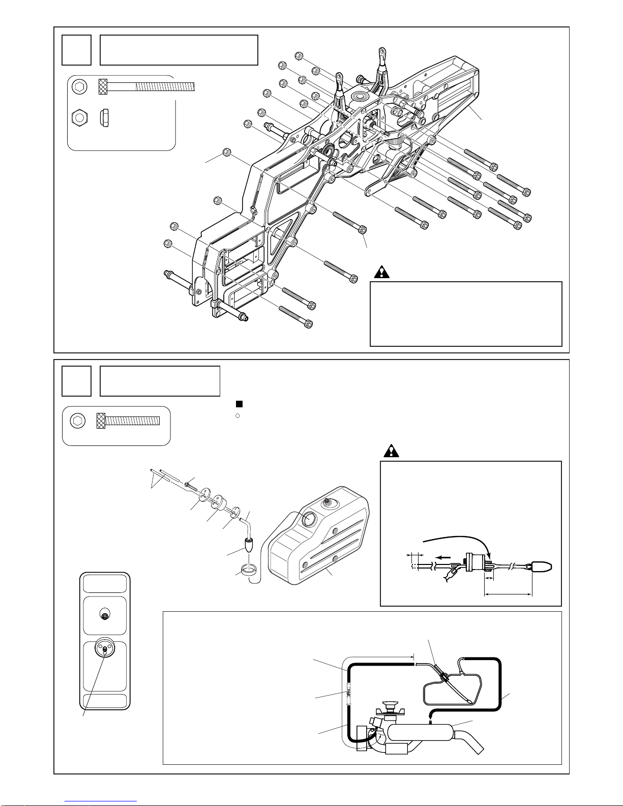
13
燃料タンクの組立
Fuel tank assembly
5
燃料タンクオモリのつい
たチューブの取出口。
Connectionopeningforthe
tubewiththefueltankweight
燃料タンク(上面より見て)
Fueltank(Topview)
M3X20CS............................. 1
■燃料パイプの配管
○
燃料タンクのオモリの付いたパイプにシリコンパイプ(別売)をハメ込み、エンジンのキャ
ブレターへ接続します。(別売の燃料フィルターを付けると良いでしょう)
Fuel lines
Install silicon fuel tubing (not included) onto the SUS pipes before installing the tank into the main
frame. See suggested lengths below. Alsoinstall a fuel filter (not included) between the tank’s engine
fuel line connection (inside tank fuel line with “clunk” attached) and the engines carburetor fuel inlet.
燃料パイプの配管はエン
ジンの種類及びマフラー
プレッシャーの使用、不
使用によっても異なりま
す。各エンジンの説明書
をよく読んで行って下さ
い。
The connection of the fuel
tubing to the fuel tank may
differ depending on the
kind of engine and/or use
of muffler pressure. Please
carefully read the
instruction manual of each
engine.
抜け防止のためA側のシリコンチューブを6mm程
使用してカバーする。
Use 6-8mm of remaining tank internal fuel line
provided to secure the “clunk” line to the 10mm
pipe length protruding inside of the tank thus
preventing the line detaching during flight.
Note the “A” side is the inside portion of the
fuel tank cap.
燃料タンク
Fuel tank
シリコンチューブ
Silicon tubing
タンクアウターリング
Fuel tank outer ring
小
Small
大
Large
タンクキャップ
Tank cap
SUS パイプ
SUS pipe
燃料タンクオモリ
Fuel tank weight
M3X20CS
マフラーのプレ ッシャーへ
To the muffler or pump pressure connection
燃料フィルター
(別売)
Fuel filter
(not included)
Suggested Refueling line, plug for flight
エンジ ンのキャブレターへ
To the engine carburetor
マフラー
Muffler
シリコンチューブ
(別売)
Silicon tubing
(not included)
約220mm
Approx.220mm
シリコンチューブ
(別売)
Silicon tubing
(not included)
給油用(フラ イト時には栓をして下さい)
A
100〜110mm
10mm
約45˚曲げる
Bend approx 45˚
約6mm
Approx 6mm
M3X32CS ........................... 14
M3ナイロンナット(薄型)....
14
M3 nylon nut (thin type)
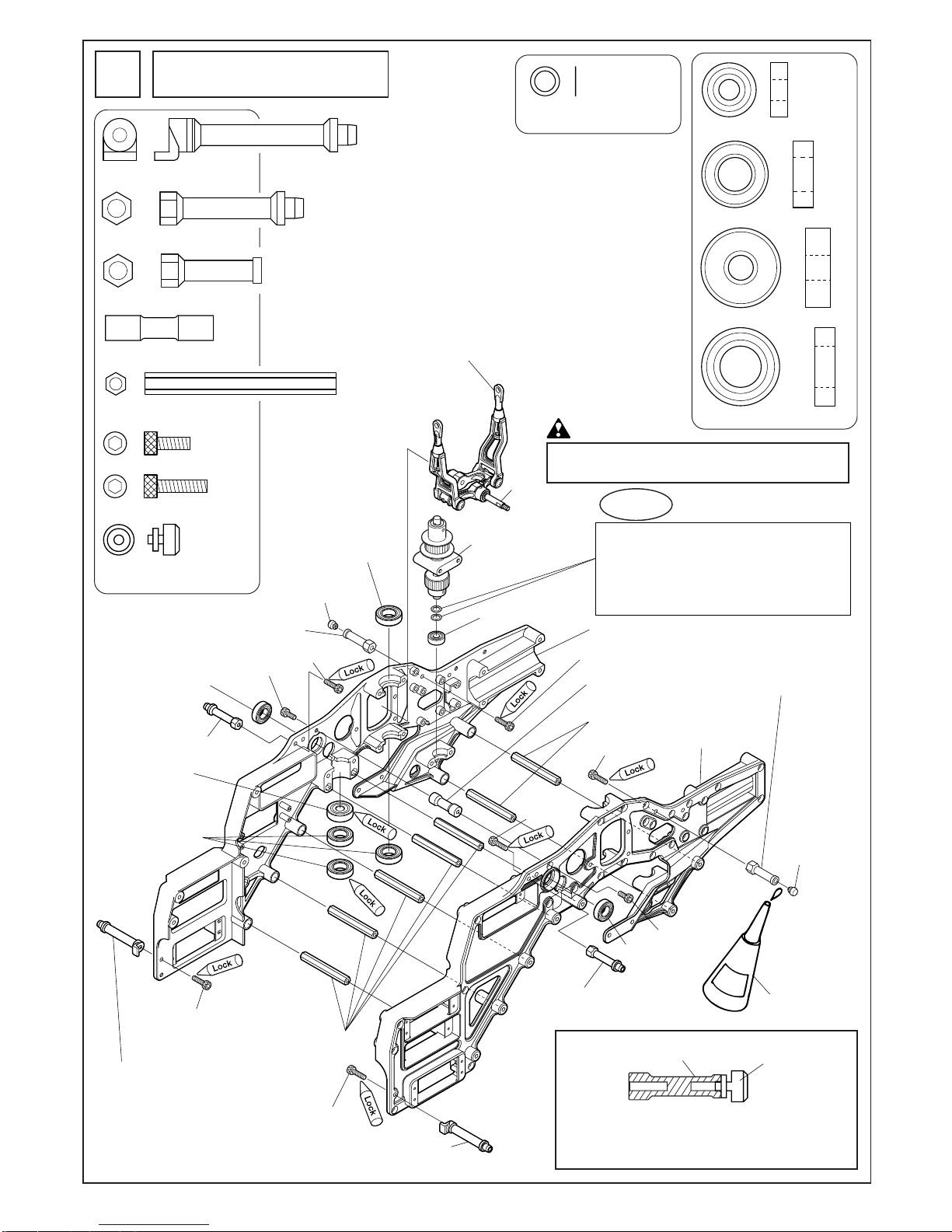
サーボフレームの組立-2
Servo frame assembly-2
4
M3ナイ ロンナッ ト(薄型)
M3 nylon nut (thin type)
M3X32CS
サーボ フレームAssy
Servo frame assembly
注意 Caution
M3X32CSを締めすぎると、フレームが変形してベア
リングがスムーズに回らなくなります。
参考値:締付トルクは約5kgf•cm です。
注意 Caution
Tightening M3x32CS screws too tight will deform
the frame, thus preventing smooth bearing rotation.
Use moderate hand tightening only.

14
M3X15CS
M3X12CS
M3X8TS
M3X8CS
FW ø3Xø8X0.5
M3X8TS
M3X8TS
M3X15CS
M3X15CS
M3X12CS
M3X12CS
M3X12CS
クロスメンバーM3X64
Cross member M3X64
メカプレー ト
Mechanical plate
スイッチプレート
Switch plate
燃料タンクAssy
Fuel tank assembly
サーボ フレームAssy
Servo frame assembly
メインフレーム(L)
Main frame (Left)
メインフレーム(R)
Main frame (Right)
M3X32CS
防振ゴムø10
Rubber cushion ø10
防振ゴムø10
Rubber cushion ø10
M3ナイ ロンナッ ト(薄型)
M3 nylon nut (thin type)
M3ナイ ロンナッ ト(薄型)
M3 nylon nut (thin type)
M3ナイ ロンナッ ト(薄型)
M3 nylon nut (thin type)
クロスメンバーM3X64 ...... 2
Cross member M3X64
M3X8CS ............................... 2
M3X12CS ............................. 4
M3X32CS ............................. 1
M3X15CS ........................... 18
M3X8TS ............................... 4
M3ナイロンナット(薄型)......
7
M3 nylon nut (thin type)
FW ø3Xø8X0.5 .................... 2
メインフレームの組立
Main frame assembly
6
メインフレームの穴部に防振ゴムをはめ込み、燃料タンクの
凹部をはめ込んでください。
メインフレーム
Main frame
防振ゴム
Rubber cushion
燃料タンク
Fuel tank
Install 6 rubber cushions into the main frame fuel tank mounting
holes.
Make sure the fuel tank is fully seated onto the cushions as
illustrated above.
注意 Caution
防振ゴムø10 ........................ 6
Rubber cushion

15
アンテナパイプ
Antenna pipe
スキッドパイ プキ ャ ップ
Skid pipe cap
瞬間接着剤
Instant adhesive
瞬間接着剤
Instant adhesive
スキッドパイ プキ ャ ップ
Skid pipe cap
スキッドパイ プ
Skid pipe
スキッドフット
Skid foot
M3ナイ ロンナッ ト
M3 nylon nut
M3ナイ ロンナッ ト
M3 nylon nut
M2.6ナイ ロンナッ ト
M2.6 nylon nut
M2.6ナイ ロンナッ ト
M2.6 nylon nut
M2.6ナイ ロンナッ ト
M2.6 nylon nut
M2.6ナイ ロンナッ ト
M2.6 nylon nut
M3ナイ ロンナッ ト
M3 nylon nut
M3ナイ ロンナッ ト(薄型)
M3 nylon nut (thin type)
M3ナイ ロンナッ ト
M3 nylon nut
M3X18CS
M3X18CS
M2.6X10CS
M2.6X10CS
FW ø3Xø9X1T
FW ø3Xø9X1T
FW ø3Xø9X1T
FW ø3Xø9X1T
FW ø3Xø9X1T
0404-701
EXフローティ ングゴム
EX floating rubber
M2.6X10CS
M2.6X10CS
2532-003
M3X10CS
M3X18CS
M3X18CS
オプション
Option
コードNo.
Code No.
入数
Q'ty
品 名
Name
0404-701
EXフローティングゴム
EX floating rubber
2,100
(2,000)
315
(300)
2531-002
10
4
セットスクリューM3X5
Set screw M3X5
420
(400)
2532-003 10
キャップスクリューM3X10
Cap screw M3X10
*The prices in parentheses are the prices excluding consumption tax.
税込価格
(税抜価格)円
Price (Yen)
オプションのEXフロ
ーティングゴムが取付
可能です。
Optional EX Floating
Landing Gear Rubbers
can be used. See info
above.
ランディングギヤの取付
Landing gear installation
7
M3X18CS ............................. 8
M3ナイロンナット............. 8
M3 nylon nut
M2.6X10CS .......................... 4
M2.6ナイロンナット.......... 4
M2.6 nylon nut
FW ø3Xø9X1T ..................... 8
Advice
アドバイス
M2.6X10CSは締めすぎに注意してください。ネジの出面がナットと面一になるく
らいで十分です。
また、スキッドフットとスキッドパイプの間に必ず瞬間接着剤を流してください。
Do not over tighten M2.6x10CS screws. When nut is fully seated in skid foot, this is sufficient.
Please use instant adhesive to additionally secure skid pipe to skid foot.
スキッドフットは長期間使用するとスキッドパイプの
締め付けが弱くなる場合があります。
その場合は図のようにø2.4ドリルで穴を空けてネジ止
めしてください。
Additional screws can be used to further secure skid pipe to
the skid foot as illustrated.
2531-002
M3X5SS
ø2.4 hole
ø2.4 穴
(別売)
(Sold separately)

16
メインマスト
Main mast
185mmの穴を使用して
ください。
Use holes for 185mm length.
185mm
195mm
199mm
メインマスト
Main mast
溝あり(60用)
.60/.70 mast has
groove at bottom.
メインギヤ 95T(60-70用)
Main gear 95T(for 60-70)
セカ ン ドギ ヤ
Second gear
セカ ン ドギ ヤAssy工場組立済
Second gear assembly
(pre-assembled)
M3X5CS
M3X8CS
(マストへ固定 )
(attach to main mast)
M3X5CS
C ø3Xø5X4.1
Brg. ø12Xø21X5ZZ
Brg. ø12Xø21X5ZZ
Brg. ø12X16Lワンウェイ
Bearing ø12X16L one way
C ø3Xø5X4.1
オートロ駆動軸
Auto-rotation
drive shaft
オートロケース
Auto-rotation case
(マストへ固定 )
M3X8CS
M3X8CS
(affixed on the mast)
メインマストをいっぱい引っぱり上げ、マストロック
を通しM2.6X6CSで締付けます。
Pull the main mast up through the mast lock and fasten
with 2.6X6CS.
注: マストが上下にあそびがない事。
Note: Make sure mast assembly has no end play.
メインマストを引っぱり
上げる。
Pull main mast up fully.
マストロック
Mast lock
マストロックをいっぱい
下げる。
Install mast lock firmly
against upper main
shaft bearing.
M2.6X10TS-2(座金付)
M2.6X10TS-2 (with attached washer)
FW ø3Xø4.5X0.5T
FW ø3Xø4.5X0.5T
EX メインギヤ 95T(80-90用)
EX Main gear 95T(for 80-90)
平らな面が
下になります。
M2.6X6CS
ø10ハードグリップマストロック
10mm Mast lock clamp
メインギヤの取付
M3X8CS ............................... 2
M2.6X10TS-2(座金付) ........ 6
M2.6X10TS-2
(with attached washer)
M2.6X6CS ............................ 1
C ø3Xø5X4.1 ........................ 2
注意
ロック
Lock
フリー
Free

17
スワッシュプレート部の組立
Swash plate assembly
9
ピボットボルトがスワッシュプレートに締め込みにくい場合は、
はじめにM3CS 等のネジを使い、ネジ山を切っておくと、締め
込み易くなります。
Use a 3mm screw to tap threads into outer ring of
swashplate. Use instant adhesive to secure pivot bolts and
do not over tighten. If pivot bolts are over tightened, the
mounting tabs may crack.
注意 Caution
ピボットボルト(D)............. 3
Pivot bolt (D)
ピボットボルト(E) ............. 4
Pivot bolt (E)
ピボットボルトの見分け方
How to distinguish between pivot
bolts (E) and (D).
ピボット
ボルト (D)
Pivot bolt (D)
ピボット
ボルト (E)
Pivot bolt (E)
ウォッシュアウト部の組立
Washout assembly
10
Brg. ø3Xø7X3FZZ ............... 4
M3X12CS ............................. 2
M2X8CS ............................... 2
FW ø3Xø4.5X0.5T ............... 2
EX ø5ボール ........................ 2
EX ø5 ball
ニードルピンø2X11.8 ........ 2
Needle pin ø2X11.8
ウォッシュアウトコントロール
アームの向きに注意してください。
Note washout control arm
orientation.
注意 Caution
4mm
7mm
ピボットボル ト(E)
Pivot bolt (E)
ピボットボル ト(D
)
Pivot bolt (D)
ピボットボル ト(E
)
Pivot bolt (E)
ピボットボル ト(E)
Pivot bolt (E)
ピボットボル ト(D)
Pivot bolt (D)
ピボットボル ト(D)
Pivot bolt (D)
スワッシュプレート
Swash plate
スライ ドブロック
Slide block
ウォッシュアウトコントロールアーム
Washout control arm
ラジアスアーム
Radius arm
ラジアスアーム
Radius arm
ニードルピンø2X11.8
Needle pin ø2X11.8
M3×12CS
M3X12CS
M2X8CS
M2X8CS
EX ø5 ボー ル
EX ø5 ball
EX ø5 ボー ル
EX ø5 ball
Brg. ø3Xø7X3FZZ
FW ø3Xø4.5X0.5T
FW ø3Xø4.5X0.5T
Brg. ø3Xø7X3FZZ
Brg. ø3Xø7X3FZZ
ニードルピンø2X11.8
Needle pin ø2X11.8
ウォッシュアウトコントロールアーム
Washout control arm

18
ヨーク
Yoke
センターハブ
Center hub
ダンパーゴム
Damper rubber
凹みのある
方
Concave side
凹みのある方
Concave side
ダンパーゴム
Damper rubber
M4X12CS
M4X12CS
M4X10CS
M4X10CS
FW ø3Xø8X0.5
ストッププレート
Stop plate
M3X8ボタンボルト
M3X8 button bolt
Brg. ø5Xø13X4FZZ
Brg. ø4Xø8X3FZZ
C ø4Xø5X4.3 F7X0.4
C ø4Xø5X4.3 F7X0.4
Brg. ø5Xø13X4FZZ
工場圧入済
Press fit bearing
スピンドル
Spindle
ヨーク
Yoke
ブレードホルダー
Blade holder
Brg. ø8Xø16X5
C ø12Xø15X6.8
Brg. ø8Xø16スラスト
Bearing ø8Xø16 thrust
FW ø5Xø12X1.5T
FW ø8Xø12X0.1T
M2X12CS
EX ø5ボール
EX ø5 ball
ボタンボル トM5X10
Button bolt M5X10
ブレードホルダーAssy工場組立済
Blade holder assembly
(pre-assembled)
OリングP-7
O ring P-7
中央の穴を使用します。
Use the center hole.
ポイント
Point
Brg. ø8Xø16 スラスト
Bearing ø8Xø16 thrust
ブレードホルダー
Blade holder
内径の大きい方
Larger hole
内径の小さい方
Smaller hole
ミゾが内側
Grooves are
inside
必ず
グリスを塗 付
Make sure to
a
pply grease
ヨーク部の組立
Yoke assembly
11
ダンパーゴムがヨークから出っ張らな
いよう少量のオイルをつけて、しっか
りと押し込みます。
Coating the outside of the damper
with a small amount of silicone oil
will aid with full seating of the
damper into the yoke.
Use of “red” or “permanent” grade
thread lock is highly recommended
for damper and yoke bearing bolt
attachment to the center hub.
During pre-flight inspections check
the bolts for proper tightness.
注意 Caution
ボタンボルトM3X8............ 1
Button bolt M3X8
M4X12CS............................. 2
M4X10CS............................. 2
Brg. ø5Xø13X4FZZ ............. 2
C ø4Xø5X4.3 F7X0.4........... 2
FW ø3Xø8X0.5T .................. 1
M2X12CS............................. 2
ボタンボルトM5X10.......... 2
Button bolt M5X10
Brg. ø8Xø16スラスト ......... 2
Bearing ø8Xø16 thrust
FW ø5Xø12X1.5T ................ 2
EX ø5ボール........................ 2
EX ø5 ball
ヨーク /ブレードホルダー部の組立
Yoke and blade holder assembly
12
FW ø8Xø12X0.1T ................ 4
(調整用)
FW ø8Xø12X0.1T
(for adjustment)
注意 Caution
注意 Caution
ブレードホルダーとヨークの間にスキ間がある場合のみ、使用してく
ださい。入れすぎると、ブレードホルダーが動きにくくなります。必
ずブレードホルダーはスラスト方向に0.1mm程度のあそびを残し
ておいてください。
These shims are only for use if there is excessive side to side
play of the blade grips after this assembly step is completed.
It is normal to allow .1 mm of play. Using too many shims will
cause the blade grips to not to rotate smoothly.
OリングP-7.......................... 2
O ring P-7
Brg. ø4Xø8X3FZZ ............... 2

19
C ø2.6Xø4X4F
C ø2.6Xø4X12S
C ø2.6Xø4X12S
小
Small
大
Large
C ø2.6Xø4X4F
FFZ-IIIミキシングアーム
FFZ-III mixing arm
FFZ-IIIミキシングアーム
FFZ-III mixing arm
EX ø5ボー ル
EX ø5 ball
EX ø5ボー ル
EX ø5 ball
M2X6CS
M2X6CS
M2.6X15CS
M2.6X15CS
M2.6X8CS
A
Brg. ø4Xø8X3ZZ
Brg. ø4Xø8X3ZZ
Brg. ø4Xø8X3ZZ
FFZ-IIIシーソー
FFZ-III seesaw
Brg. ø4Xø9X4ZZ (圧入済)
Bearing ø4Xø9X4ZZ (Press fit bearing)
Brg. ø4Xø9X4ZZ (圧入済)
Bearing ø4Xø9X4ZZ (Press fit bearing)
Brg. ø4Xø8X3ZZ
1
2
3
1
1
3
3
2
Brg. ø4Xø8X3FZZ (圧入済)
Bearing ø4Xø8X3FZZ (Press fit bearing)
M2.6X8CS
Brg. ø4Xø8X3FZZ (圧入済)
Bearing ø4Xø8X3FZZ(Press fit bearing)
この穴を使用します。
Use these holes for initial setup.
ポイント
Point
この穴を使用します。
Use this hole.
修正率 Adjustment ratio
修正率とは、スタビライザーバーの傾き角に対するブレードホルダ
ーのピッチ変化の比率です。修正率が大きい場合、スタビライザー
バーの傾き角に対するブレードホルダーのピッチ変化が大きいこと
を意味します。
The adjustment ratio is the ratio of the change in the blade holder pitch to
the stabilizer bar angle. When the adjustment ratio is high, the ratio of the
change in the blade holder pitch to the stabilizer bar angle is high.
フレイヤEVOでは、③の穴でローターヘッドの比率を調整しています。
① ②の穴を使用する場合は、ピッチを再調整して各自のフィーリン
グに合わせたセッティングを行ってください。
※フライトフィーリングはローター回転数やブレードの種類、スタ
ビライザーバーの長さ、エンジンのパワー等によっても変化します。
The rotor head ratio of the Freya EVO is adjusted with the ③ holes.
When using the ① and ② holes, readjust the pitch to match the flight
feeling.
* The flight feeling varies with the rotor speed, type of blade, stabilizer bar
length, and engine power, etc.
シーソーの取付向きにご注意ください。
Note the direction of the seesaw.
注 意 Caution
A から見た図
View from A
①、③を使用
する場合
When using the
① or ③ settings
②を使用する場合
When using the ②
setting
ミキシングアームの取付位置は③を使用して下さい。
Attach mixing arms at location ③ for initial setting.
シーソー部の組立
Seesaw assembly
13
Brg. ø4Xø8X3ZZ.................. 4
Brg. ø4Xø9X4ZZ.................. 2
M2.6X15CS.......................... 2
M2.6X8CS............................ 2
M2X6CS............................... 4
C ø2.6Xø4X12S ................... 2
C ø2.6Xø4X4F ..................... 2
EX ø5ボール........................ 4
EX ø5 ball

20
スタビライザーコン トロールロッド(2 set)
Stabilizer control rod (2 sets)
スタビライザーコン トロールロッド
Stabilizer control rod
40mm
24mm
スタビライザーバー
Stabilizer bar
ø5ボール付クロスメンバーM2X109
Cross member M2X109 with ø5 ball
スタビコン トロールアーム
Stabilizer control arm
スタビコン トロールアーム
Stabilizer control arm
仮止め
Set temporarily and
secure during final setup
M4X4SS
M2X8CS
M2X8CS
仮止め
Set temporarily and
secure during final setup
M4X4SS
スタビバーストッパー (圧入済)
Stabilizer bar stopper (Press fit)
スタビバーストッパー (圧入済)
Stabilizer bar stopper (Press fit)
スタビアーム部の組立
Stabilizer control arm assembly
14
M2X8CS ............................... 4
M4X4SS ............................... 2
ロッドエンド ...................... 4
Rod end

21
キャップ
Cap
ø3ウエイト(組立済)
ø3 weight (pre-assembled)
スタビライザーバー
Stabilizer bar
スタビストッパー
Stabilizer stopper
スタビブレード
Stabilizer blade
M3X3SS
M3X3SS
ø4ウエイト(組立済)
ø4 weight (pre-assembled)
接着
Adhere
A=B=121〜122
B
A
スタビライザーブレードとスタビライザー
コントロールアームは平行であること。
The stabilizer blade and control arms must be parallel.
スタビライザーバー
Stabilizer bar
スタビストッパー
Stabilizer stopper
スタビブレード
Stabilizer blade
M3X3SS
ネジ切り
Threads
M3X3SS
Advice
アドバイス
スタビブレード部の組立
Stabilizer blade assembly
15
スタビライザーブレードのバランスを取り、軽い方にテープな
どを巻いて調整してください。
If needed, balance paddles using a sticker or adhesive tape.
Add to the lighter paddle only.
注意 Caution
M3X3SS ............................... 4
ウエイトは取り外しが可能です。
飛行内容によってお好みの設定をしてください。
フライト後はø3ウエイトが抜けにくくなる場合があります。
無理に抜こうとするとちぎれてバランスがとれなくなる恐
れがありますので、フライト後はø4 ウエイトで調整して
ください。
The paddle weights are removable. Feel free to adjust the weights
to suit your flying style. Note that the 3mm lead weight may be
more difficult to remove after initial flights and may separate
inside the paddle when attempted to remove. Please make
adjustments to the 4mm brass weight after first flight.
スタビストッパーの方向にご注意ください。
Note the direction of the stabilizer stopper.
注意 Caution
注意 Caution
両方のスタビライザーブレードをスタビライ
ザーバーに最後までねじ込みます。(強く締め
込まないで下さい。)
A=B の距離が同じになるように位置を調整し
ます。
M3X3SS は最後に締め込みます。
Thread each paddle onto the stabilizer bar until it
stops. Align paddles parallel to each other, but do
not overtighten. Measure distances A & B and make
the same. For the 490mm stabilizer bar, start with
A & B at 121mm each side. Secure 3mm paddle
set screws during final set up.

22
M4X10CS
ラジアスブロック
Radius block
M2X10CS
M2 ナッ ト
M2 nut
M4X10CS
ウォッシュアウ ト
Washout
スワッシュプレー ト
Swash plate
M4X4SS: 先にM2X10CSとM2ナッ ト
を締めて下さい。
Fasten the M2X10CS screws
and nuts first. Tighten M4X4S
after initial radius block setting
is made.
ローターヘッド部/ ウォッシュアウト部 / スワッシュプレート部の取付
Rotor head, washout, and swashplate installation
16
M4X10CS............................. 2
M2X10CS............................. 2
M2ナット............................. 2
M2 nut
M4X4SS ............................... 1
ピッチハイの時
At full positive pitch
ココが干渉しない様にする。
Shorten stabilizer control rods to
prevent interference in this area.
長さ調節
Adjust
the length
長さ調節
Adjust the
length
A
A'
B
B'
スワッシュプレー ト
アッパーのø5ボール
Inner ø5 ball of
the swash plate
スワッシュプレー ト
ロアーの ø5ボー ル
Outer ø5 ball of
the swash plate
AA'//
BB'
AA':
機体の中心軸
A,A’:center line of heli
main frame
BB':
スタビライザーバー
Stabilizer bar
アジャストロッド
Adjustment rod
図-2
Fig. 2
ピッチハイの時
At full positive pitch
センターハブ
Center hub
ピン
Pin
ラジアスブロック
Radius block
スライドブロック
Slide block
図 -3
Fig. 3
図-1
Fig. 1
ラジアスブロックは、センターハブにぴったり
くっつけます。(図 -1)
次に、ピッチがフル Hi の時にエレベーターをいっ
ぱいに切ってもスワッシュアッパープレートと、
ウォッシュアウトコントロールアームのM2ロッド
エンドに干渉が生じない様にアジャストロッドの
長さを調節して下さい。(図 -2)
以上の調節の後、機体を真上から見て、スワッシュ
プレートのアッパーとロアーの ø5 ボールが同一直
線上にあるとき、フレームに対してスタビライ
ザーバーが平行になる様、ラジアスブロックを
M2X10CSと M4X4SS で固定して下さい。(図 -3)
なお、正確な位相調整は実際の飛行により行ない
ます。
Install radius block onto main mast up against bottom of
rotor head center hub. See fig. 1.
Initially set the “swashplate phasing” as per Fig. 3 and
lightly secure two M2X10CS screws in the radius block.
Move the collective lever to full positive pitch (collective
lever down, swashplate up) and tilt swashplate forward
and backward. If stabilizer control rod ends hit inner ring
of swashplate, shorten rods until rod ends no longer contact
swashplate in this position. Final adjustment can be
changed to level washout arms during final set up as well.
For final “swashplate phasing” setting, set the radius block
so when the swashplate is viewed from above, and the
stabilizer bar is parallel to the main frame’s center line,
the inner and outer swashplate ring pivot balls are aligned
and there is a slight angle to the stabilizer control rods.
Final phase setting is made after initial flights. Be sure to
secure the M4X4SS in the radius block during final set
up. If the radius block is not aligned properly or securely
fastened, cyclic controls will be mixed, affecting proper
flight operation.
ぴったりくっつける
Attach firmly

23
X型レバー(R)
X-type lever (Right)
T型レバー
T-type lever
X型レバー(L)
X-type lever (Left)
EX ø5 ボー ル
EX ø5 ball
EX ø5 ボー ル
EX ø5 ball
EX ø5 ボー ル
EX ø5 ball
EX ø5ボー ル
EX ø5 ball
EX ø5ボー ル
EX ø5 ball
EX ø5 ボー ル
EX ø5 ball
M2X6CS
M2X6CS
M2X6CS
M2X6CS
EX ø5ボー ル
EX ø5 ball
M2X6CS
エルロン レバー
Aileron lever
EX ø5 ボー ル
EX ø5 ball
EX ø5 ボー ル
EX ø5 ball
ロゴのない方
The side with no logo
EX ø5 ボー ル
EX ø5 ball
M2X6CS
M2X6CS
M2X6CS
クロスメンバーM3X40
Cross member M3X40
コレクトピッチシャフ ト
Collective pitch shaft
M3X40 クロスメンバー
Cross member M3X40
コレクトピッチレバー (L)
Collective pitch lever (Left)
コレクトピッチボルト
Collective pitch bolt
コレクトピッチレバー (R)
Collective pitch lever (Right)
C ø4Xø7X1.5
段のある方が
ベア リング側になります
。
The side with a step
faces the bearing.
M3X8CS
コレクトピッチボルト
Collective pitch bolt
M3X8CS
EX ø5 ボー ル
EX ø5 ball
M2X6CS
FW ø5Xø10X1T
FWø5Xø10X1T
コレクトピッチレバーの取付
Collective pitch lever installation
17
M3X8CS ............................... 4
M2X6CS ............................... 1
FW ø5Xø10X1T ................... 2
EX ø5ボール ........................ 1
EX ø5 ball
C ø4Xø7X1.5 ........................ 1
クロスメンバーM3X40 ...... 2
Cross member M3X40
X型レバー / エルロンレバーの組立
X-type and aileron lever assembly
18
M2X6CS ............................. 14
EX ø5ボール ...................... 14
EX ø5 ball
リンケージの際、EX ø5ボールの取り付けた裏側のボスがロッドエ
ンドと干渉する場合、ボス部をヤスリなどで削り取ってください。
When moving linkages on these levers, if any raised portions
behind the EX ø5 balls interfere with rod ends, use a filing tool
to reduce the raised area accordingly that is hitting the rod end.
注意 Caution
EX ø5ボールを取り付ける位置に十分注意して下さい。
注意 Caution
Carefully fix the EX ø5 ball to the correct location.
Do not over tighten M2X6CS in plastic as the levers
may crack.

24
M4X4SS
X型レバー(L)
X-type lever (Left)
C ø4Xø6X2
X型レバー
(R)
X-type lever
(Right)
エルロン レバー
Aileron lever
T型レバー
T-type lever
C ø4Xø6X5
C ø3Xø4-ø6X15.5
M3ナイ ロンナッ ト
M3 nylon nut
M3ナイ ロンナッ ト
M3 nylon nut
M3ナイ ロンナッ ト
M3 nylon nut
エレベーター トルクレバー
Elevator torque lever
Brg. ø3Xø8X4ZZ
Brg. ø4Xø8X3ZZ
Brg. ø4Xø8X3ZZ
Brg. ø4Xø8X3ZZ
Brg. ø3Xø8X4ZZ
C ø3Xø5X1
C ø3Xø5X1
Brg. ø4Xø8X3FZZ
Brg. ø4Xø8X3FZZ
M2.6X8CS
M3X25CS
注意Caution
注意Caution
締めすぎるとコレクトピッ
チボルトが折れる場合があ
ります。
The collective pitch bolt
may break if the M3 nylon
nut is over tightened.
締めすぎるとコレクトピッチボルトが
折れる場合があります。
The collective pitch bolt may break if
the M3 nylon nut is over tightened.
X型/エルロン/ エレベータートルクレバーの取付
X-type, aileron, and elevator torque lever installation
19
M2.6X8CS ............................ 1
M3X25CS ............................. 1
Brg. ø3Xø8X4ZZ.................. 2
Brg. ø4Xø8X3ZZ.................. 4
Brg. ø4Xø8X3FZZ ............... 2
M4X4SS ............................... 1
C ø4Xø6X5 ........................... 1
C ø4Xø6X2 ........................... 2
C ø3Xø5X1 ........................... 2
C ø3Xø4-6X15.5 .................. 1
M3ナイロンナット............. 4
M3 nylon nut
エレベータートルクレバーは、
エレベーターレバーと垂直にな
るように取り付けてください。
Install the elevator torque lever
perpendicular to the elevator
lever.
注意 Caution
20
タイミングベルトは、折り曲げたり、キズをつけ
たりしないでください。破損の原因になります。
To reduce the risk of damage, do not bend or
scratch the timing belt.
注意 Caution
Brg. ø5Xø13X4ZZ................ 2
M3X15CS............................. 7
C ø5Xø8X2.5........................ 1
M3ナイロンナット(薄型)......
7
M3 nylon nut (thin type)
FW ø5Xø7X0.1 .................... 2
(調整用)(for adjustment)
テールケース部の組立
Tail case assembly
M3ナイ ロンナッ ト(薄型)
M3 nylon nut
Brg. ø5Xø13X4ZZ
C ø5Xø8X2.5
ベルトプーリー(シ ャフト付き )
Belt pulley (with attached shaft)
タイミングベ ルト
Timing belt
テールケース(R)
Tail case (Right)
テールケース(L)
Tail case (Left)
Brg. ø5Xø13X4ZZ
仮止め
Set temporarily
M3X15CS
M3X15CS
FW ø5Xø7X0.1(調整用)
(for adjustment)
ポイント
Point
軸方向のあそびが多い場合に使用して下
さい。 入れすぎると回転が重く なります。
Use shim only if there is end play in tail
output shaft after tail case assembly.
If used with no end play, the tail output
shaft will bind in bearings.
エレベーターレバー
Elevator lever
エレベーター トルクレバー
Elevator torque lever
90°

25
テールブレー ドホルダー(B)
Tail blade holder (B)
テールブレー ドホルダー(A)
Tail blade holder (A)
Brg. ø4Xø9X4ZZ
テールハウジング
Tail housing
Brg. ø4Xø9スラス ト
Bearing ø4Xø9 thrust
M3X16CS
M2X8CS
M2X8CS
Brg. ø3Xø9X3
M3 ナイ ロンナッ ト
M3 nylon nut
M2 ナッ ト
M2 nut
FW ø3Xø6X0.5T
FW ø3Xø8X0.5T
FW ø3Xø8X0.5T
対称テールブレードL=92
Symmetrical tail blade L=92
EX ø5 ボー ル(台付)
EX ø5 ball (with stand)
テールハウジ ン
グ
→
Tail housing
内径の大きい方
Larger hole
内径の小さい方
Smaller hole
グリスを塗付します 。
Apply grease
必ず
グリスを塗付
Make sure to a
pply grease
21
Brg. ø4Xø9X4ZZ.................. 2
Brg. ø4Xø9スラスト ........... 2
Bearing ø4Xø9 thrust
Brg. ø3Xø9X3 ...................... 2
M2X8CS............................. 10
M3X16CS............................. 2
FW ø3Xø8X0.5T .................. 4
FW ø3Xø6X0.5T .................. 2
M2ナット............................. 2
M2 nut
M3ナイロンナット............. 4
M3 nylon nut
EX ø5ボール台付................ 2
EX ø5 ball (with stand)
テールブレード、及びテールブレードホ
ルダーの向きにご注意ください。
Note the directions of the tail blade and
the tail blade holder.
注意 Caution
テールブレードは軽く動く程度に締
め込んでください。
Fasten tail blades snugly yet
allowing them to move slightly.
注意 Caution
テールハウジング部の組立
Tail housing assembly
テールピッチプレートの組立
Tail pitch plate assembly
22
FW ø6Xø8X0.3T
M6ナット(薄型)
M6 nut (thin type)
W型テールピッチプレートボス
Double type tail pitch plate boss
Brg. ø6Xø10X3ZZ
Brg. ø6Xø10X3ZZ
C ø6Xø7X3
Eリングø1.5
E-ring ø1.5
スライド軸
Slide shaft
テールピッチリンク
Tail pitch link
テールピッチプレート
Tail pitch plate
テールピッチリンク
Tail pitch link
Eリングø1.5
E-ring ø1.5
Eリングø1.5
E-ring ø1.5
Eリングø1.5
E-ring ø1.5
ミゾ付き平行ピンø2X11.6
Grooved parallel pin ø2X11.6
ミゾ付き平行ピンø2X11.6
Grooved parallel pin ø2X11.6
テールピッチプレートAssy工場組立済
Tail pitch plate assembly
(pre-assembled)
注意 Caution

26
M3X5SS
テール ピ ッチプレートAssy
Tail pitch plate assembly
ガイドピンM3X6.3
Guide pin M3X6.3
レバーカ ラ ー
Lever collar
テール ピ ッチレバ
ー
Tail pitch lever
FW ø4Xø6X0.5T
FW ø4Xø6X0.5T
Brg. ø4Xø8X3ZZ
Brg. ø4Xø8X3ZZ
M2X6CS
M2.6X8CS
M2.6X8CS
EX ø5 ボー
ル
EX ø5 ball
テールハウジ ン グ
Tail housing
テールプー リーシ ャ フ ト
Tail pulley shaft
M3X5SS
Brg. ø4Xø8X3ZZ................... 2
M2.6X8CS ............................. 2
M2X6CS ................................ 1
M3X5SS ................................ 1
FWø4Xø6X0.5T .................... 2
EX ø5ボール .........................1
EX ø5 ball
ガイドピンM3X6.3 ..............2
Guide pin M3X6.3
シャフトのくぼみに合わせて締め込む。
Align tail housing with dimple on end
of tail output shaft and fasten with
M3x5SS. See diagram below.
注意 Caution
テールピッチガイドピンは、テール
ピッチプレートの溝にはまるように
取り付けてください。
Install M3x6.3 guide pin into tail
pitch plate groove. Ensure
smooth movement.
注意 Caution
テールハウジング部の取付
Tail housing installation
23
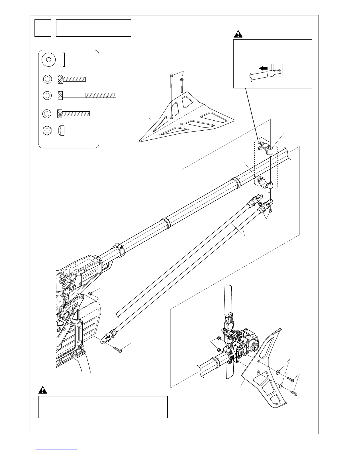
テールブームパイプ部の取付
Tail boom pipe installation
24
八角テールブームパイ プL=805
Octagonal tail boom pipe L=805
本締め
Tighten after installing
on tail boom

27
エポキシ接着剤
Epoxy adhesive
エポキシ接着剤
Epoxy adhesive
M2.6X15CS
M2.6X15CS
M2.6X15CS
M2.6ナット
M2.6 nut
M2.6ナット
M2.6 nut
M2.6ナット
M2.6 nut
テールブームブレース
Tail boom brace
テールブレースターミナル
Tail boom brace terminal
テールプー リー
Tail pulley
タイミングプーリー
Timing pulley
M3X32CS
M3X32CS
M2.6X12TS-2
M3X12TS-2
M3ナイ ロンナッ ト(薄型)
M3 nylon nut (thin type)
八角テールブームパイプL=805
Octagonal tail boom pipe L=805
タイミングベルト
Timing belt
215mm
190mm
190mm
ラダーコントロールガイド
Rudder control guide
テール部の取付
Tail installation
25
M2.6X12TS-2 ....................... 3
M3X12TS-2 .......................... 2
M3X32CS ............................. 4
M3ナイロンナット(薄型)......
4
M3 nylon nut (thin type)
1. タイミングベルトは、ドライバー等で軽く押し
て、わずかにたわむ程度に張ります。
2. ベルトの回転方向を確認します。
1. To set proper belt tension, using
the round shaft portion of a screw
driver, lightly press on the side of
the belt and check that the belt
does not deflect pass the center
line of the main frame. The belt
should not “twang” or fit loose
enough to easily jump teeth.
2. Check for correct belt direction
movement. See adjacent diagram.
テールブームブレース部の組立
Tail boom brace assembly
26
M2.6X15CS .......................... 4
M2.6ナット.......................... 4
M2.6 nut
注意 Caution
28
水平尾翼
Horizontal stabilizer
M3 ナイ ロンナッ ト
M3 nylon nut
尾翼バンド(U)
Horizontal Fin mount
(Upper)
前
Front
尾翼バンド(L)
Horizontal Fin mount
(Lower)
M3 ナイ ロンナッ ト
M3 nylon nut
テールブームブレース
Tail boom brace
垂直尾翼
Vertical stabilizer
M3X15CS
M3X35CS
FW ø3Xø9X1T
M3X18CS
傾きがあり
Inclined
M3 ナイ ロンナッ ト
M3 nylon nut
FW ø3Xø9X1T ..................... 2
M3X15CS............................. 2
M3X35CS............................. 2
M3X18CS............................. 2
M3ナイロンナット............. 6
M3 nylon nut
尾翼の取付
Stabilizer installation
27
これまでの取り付けたすべてのネジが、確実に締め込まれている
か、確認してください。
Ensure all installed bolts up to this step are tight.
注意 Caution
注意 Caution
尾翼バンド(L)は下図のようになるよう
に取り付けてください。
Install the lower horizontal fin band as
shown below.

29
プーラーはフライホイールをエンジンから取外す際に使用します。
30 〜90 クラスのヒロボー製ヘリコプターでご使用になれます。
The puller is for safe and easy removal of the flywheel from the engine. This
tool fits all Hirobo 30-90 class helis.
① クラッチシューを固定していたネジを使って、 プレートをフライホ
イールに取付けます。
② ちょうボルトをねじ込んで、フライホイールをはずします。
(手で回しきれない時は、ペンチ等ではさんで回してください。)
① Attachthepullerユsplateontotheflywheelusingclutchattachmentscrews.
② Turnthewingboltclockwiseuntiltheflywheelpopsloose.Ifthewingbolt
getstootightforhanduse,usepliersorsimilar to gripthe wingbolt head
andturncarefully.
フライホイールレンチはエンジンのドライブナットを取付け、及び取
外しするための工具です。
30 〜90 クラスのヒロボー製ヘリコプターでご使用になれます。
The Flywheel wrench is used to safely and easily hold the flywheel during
tightening and loosening of the engine drive (prop) nut. This wrench will fit
all Hirobo .30-.90 class helis.
① クラッチシューを固定していたネジを使って、本品をフライホ
イールに取付けます。
② 十字レンチ等を使って、ドライブナットを取付(取外し)ます。
①Usingclutchshoescrews,attachtheflywheelwrenchtotheflywheel.In
thisexampleusethe4mmholesandwiderboltspacing.
② Holdtheflywheelwrenchwithonehandandtighten(orloosen)thedrive
nutusingacrosswrenchorsimilarasillustratedabove.Tip:wrapthe
flywheelwrenchwithashoptowelorragtocushionyourhand.
お知らせ
Information
エンジン周辺部品の着脱に便利な下記の工具を取り揃えております。是非ご利用下さい。
Hirobohighlyrecommendsthetoolslistedbelowforeasyattachmentandremovalofthefanhubassembly.Pleasecheckwithyourlocal
distributorforpriceandavailability.
プーラー
Puller
フライホイールレンチ
Flywheelwrench
[使用例]
[Usage]
[使用例]
[Usage]
60 〜90 クラス
60-90classexample
60〜 90 クラス
60-90classexample
2513-034
2513-035
¥1,029
(¥980)
¥1,890
(¥1,800)
ちょうボルト
Wing bolt
M4X10CS
(クラッチシューの取付ネジ)
(for Clutch shoe installation)
30〜50クラス
For 30-50 class
60〜90クラス
For 60-90 class
フライホイール
Flywheel
プレート
Plate
M4X10CS
(クラッチシューの取付ネジ)
(for Clutch shoe installation)
フライホイール
Flywheel
十字レンチ
Cross wrench
フライホイールレン
チ
Flywheel wrench
税込価格(税抜価格)
* The prices in parentheses are the prices excluding consumption tax.
振れ0.05mm以下
Run out is
0.05mm or less
ポイント
Point
フライホイール及びクラッチシューは、エンジンの軸に対して偏芯しないようにまっすぐに組立てることがポイント
です。
組立後、手でフライホイールを回してみて、クラッチ軸の中心が振れていなければOKです。
参考値:ダイヤルゲージ等で振れを測定した場合、図の矢印の箇所がそれぞれ0.05mm以下であれば問題ありません。
振れが大きい場合、いったんクラッチシューを外し、180度回転させたところで組み合わせると振れが少ない場合が
あります。実際に組み合わせてみて振れの少ない方を選択してください。
It is important that the flywheel and clutch shoe are precisely assembled centered and straight on the rotation axis of the engine’s
crankshaft.
After assembling the flywheel and clutch components onto the engine, using a dial indicator, rotate the flywheel and measure the
flywheel’s, the base of the clutch shaft’s and tip of the clutch shaft’s run out as indicated in the adjacent diagram.
The acceptable run out tolerance is 0.05mm or better at all 3 points indicated.
If the tolerances are off, start with the flywheel. First remove the clutch and flywheel and rotate the flywheel 90 degrees on the
collet and reassemble. If you get the tolerance, re-install the clutch and re-measure the base of the clutch shaft.
If you do not get the tolerance at this point, rotate the clutch shoe and look for an improvement. Take the better measurement of
the two positions and install the clutch shoe. Make sure when installing the clutch shoe, the shoe sits flat on the flywheel and is
easy to place into and remove off of the flywheel. Also make
sure there are no burrs on the face of the flywheel or underside of the clutch shoe as these may cause the clutch shoe to sit at an
angle on the flywheel causing excessive run out especially at the tip.

30
軸付クラッチシュー
Clutch shoe with attached shaft
プロペラナ ット(エンジ ン付属)
Propeller nut (included with engine)
M4X10CS
FW ø6X ø8X0.3T
Oリング SS060
O ring SS060
フライホイール
Flywheel
EXクーリングファン
EX cooling fan
上
Top
内側に凹部がある
のが右側(R)
The right side (Right)
is designated by a
dimple on the inner
surface.
スタータープーリー座 金
(ライン入 り )
Grooved starter pulley
Washer (included)
M3X6皿ネジ
M3X6 countersunk screw
テーパーカ ラー
Taper collar
エンジ ン(別売)
Engine (sold separately)
SXエンジ ン ブロ ック(R)
SX engine block (Right)
凹部
Dimple
少量のオイルを塗るとよいでしょ う。
It is recommended to apply a little oil.
SXエンジ ン ブロ ック(L)
SX engine block (Left)
M4X15CS
M4X15CS
テーパーカ ラー
Taper collar
80-90クラスエンジン用
ギヤー付クラッチベル(12T)
Clutch bell with attached gear(12T)
for 80-90 class engine
60-70クラスエンジン用
ギヤー付クラッチベル(10T)
Clutch bell with attached gear(10T)
for 60-70 class engine
FWø10Xø18X1.5
(エンジ ン付属のワ ッシャーは
使用しません)
(Discard washer supplied with
engine. Use washer included in kit.)
スラストワッシャー
Thrust washer
M2ナット
M2 nut
M2X6CS
2532-015
M3X15CS
EXø5ボール
2521-069
ø3X8X7カラー
ø3X8X7 collar
YSエンジンの場合はø3X8X7カラー、
M3X15CSを使用して下さい。(別売)
Use ø3X8X7 collar and M3X15CS with
the YS engine. (sold separately)
EXø5 ball
参考値:締付トルクは 150kgf・cm です。
Reference value: Fastening torque 150kgf・cm.
コードNo.
Code No.
入数
Q'ty
品 名
Name
2521-069
カラーø3X8X7
Collar ø3X8X7
315
(300)
420
(400)
2532-015
10
2
キャップスクリューM3X15
Cap screw M3X15
*The prices in parentheses are the prices excluding consumption tax.
税込価格
(税抜価格)円
Price (Yen)
エンジン部の組立
Engine assembly
28
注意 Caution
スラストワッシャー
(エンジンに付属のものは、組み立てる
前に取り外します。)
Remove prop drive washer, prop nut and
thrust washer before flywheel, clutch and
clutch bell assembly.
注意 Caution
テーパーカラーのスリットと
キー溝の位置が重ならないよ
うに組み立ててください。
Install taper collet onto crankshaft
so slit in taper collar is not over
crankshaft drive key groove.
注意Caution
エンジンブロックには、上下左右に
方向があります。
The engine mounting blocks are
directional. Take special care to install
mounting blocks as shown in all diagrams.
M3X6皿ビス........................ 4
M3X6 countersunk screw
M4X15CS............................. 4
M4X10CS............................. 2
M2X6CS............................... 1
EX ø5ボール........................ 1
EX ø5 ball
M2ナット............................. 1
M2 nut
FW ø6Xø8X0.3T .................. 1
OリングSS060..................... 1
O ring SS060

31
カラー ø4Xø5X4.5S
Collar ø4Xø5X4.5S
カラー ø4Xø5X4.5S
Collar ø4Xø5X4.5S
キャブレター(エンジン付属)
Carburetor (included with the engine)
ボタンボル トM4X14
Button bolt M4X14
ボタンボル トM4X14
Button bolt M4X14
スターターカップリング
Starter coupling
ポンチマーク
Dimple
モリブデングリス塗 布
Apply molybdenum grease
M4X4SS
クラッチ 軸
Clutch shaft
ポンチマーク
Dimple
M4X4SS
コードNo.
Code No.
入数
Q'ty
品 名
Name
0404-716
WCエンジンマウント
WC engine mount
4,200
(4,000)
630
(600)
2506-014
5
1
FW ø4焼入れ
FW ø4 hardened
*The prices in parentheses are the prices excluding consumption tax.
税込価格
(税抜価格)円
Price (Yen)
カラー ø4Xø5X4.5S
Collar ø4Xø5X4.5S
カラー ø4Xø5X4.5S
Collar ø4Xø5X4.5S
オプション
Option
オプションの0404-716 WCエンジンマウントを使用
する場合は、カラーø4Xø5X4.5Sをメインフレーム
の内側から取付け、外側からはFW ø4焼入れ(別売)
を使用します。
If the optional 0404-716 WC one piece engine mount is
used, place the ø4Xø5X4.5S collars inside the frame
between the motor mount and inside of the main frame.
Use hardened FW 4mm on outer portion of frame. All
parts needed are listed above.
2506-014
FW ø4焼入れ
FW ø4 tempered
0404-716
WCエンジンマウント
WC engine mount
2506-014
FW ø4焼入れ
FW ø4 tempered
エンジン部の取付
Engine installation
29
ボタンボルトM4X14.......... 6
Button bolt M4X14
M4X4SS ............................... 1
C ø4Xø5X4.5S ..................... 6
注意 Caution
M4X4SS をポンチマークに合わせ、
しっかりと締め付けてください。
Align the M4x4SS screw with the dimple
at the top of the clutch shaft and securely
tighten.
機体にエンジンを取り付ける前に、
キャブレターを外してください。
Install carburetor after engine is
installed. Remove for engine
installation.
注意 Caution

32
エレベーターサーボ
Elevator servo
スロットルサーボ
Throttle servo
エルロンサーボ
Aileron servo
ピッチサーボ
Pitch servo
サーボマウントスペーサー
Servo mount spacer
必要に応じて使用してください。
Use if needed.
ニードルコントロール用サーボを付ける場合
に使用します。
ニードルコンはオプションパーツ(別売)と
なります。
M2.6X16TS (座金付)
M2.6X16TS (with washer)
M2.6X16TS
(座金付)
M2.6X16TS (with washer)
M2.6X16TS
(座金付)
M2.6X16TS (with washer)
M2.6X16TS
(座金付)
M2.6X16TS (with washer)
上の穴を使います。
Use the upper holes.
M2.6X16TS
(座金付)
M2.6X16TS (with washer)
ラダーコントロールサーボ
Rudder control servo
ラダーサーボマウント
Rudder servo mount
Use this servo location if optional remote needle
control lever is added. Part number listed below.
コードNo.
Code No.
入数
Q'ty
品 名
Name
0414-219
ニードルコン トロールレバー(OS50〜90用)
Needle control lever (for OS50-90)
2,100
(2,000)
1
*The prices in parentheses are the prices excluding consumption tax.
税込価格
(税抜価格)円
Price (Yen)
サーボの取付
Servos installation
30
ネジの締め付けはグロメットがつぶれな
いように、注意してください。
Do not overtighten servo mounting
screws and possibly damaging metal
servo mounting bushings.
サーボの向きに注意!
Mount each servo in its proper
direction as shown in all
illustrations.
M2.6X16TS(座金付) ......... 20
M2.6X16TS (with washer)
注意Caution
注意Caution
ジャイロアンプとラダーサーボの間にノイズ
フィルターの使用をお勧めします。
Install a noise filter between the gyro amplifier
and the rudder servo.
Advice
アドバイス

33
受信機用バッテリー
Receiver battery
ジャイロアンプ
Gyro amplifier
受信機
Receiver
ジャイロセンサー部
Gyro Sensor
スイッチ 用
For switch
チャージングアダプター用
For charging adapter
スイッチの充電コネクタを差しておくと
配線がすっきりします。
For tidy wire arrangement, insert charging
lead as shown.
スイッチプレート
Switch plate
両面テープ
Double sided adhesive tape
スイッチ
Switch
スイッチプレート
Switch plate
スイッチ 付 属 のネジ
Switch mounting screws
スポンジ(別売)
Radio gear protective
material (sold separately)
コードNo.
Code No.
入数
Q'ty
品 名
Name
2513-052
RCメカクッションパット(ピンク)
RC mechanical cushion pad (Pink)
525
(500)
525
(500)
2513-062
1
1
RCメカクッションパット(キイロ)
RC mechanical cushion pad (Yellow)
*The prices in parentheses are the prices excluding consumption tax.
税込価格
(税抜価格)円
Price (Yen)
受信機、ジャイロ等の取付
Receiver and gyro installation
31
受信機またはバッテリーを搭載する場合は、スポ
ンジに包み込み、バンド等でしっかりと固定して
ください。
Be sure to wrap all radio gear in protective
material and firmly secure to mechanics..
Hirobo’s optional protective material with
securing strap is highly recommended. See
part #’s below.
テープを貼り付ける前に、貼り付け部分の汚れなどを十
分に拭き取ってください。
Before adhering double sided tape to any mounting
surface, clean the area thoroughly with alcohol or
similar cleaning solution.
ジャイロセンサー部には取付方向があります。
ジャイロの取扱説明書に従って取付けてください。
Mount gyro sensor as per gyro manufacturer
directions.
Before flying make sure operation direction and set
up is correct.
注意 Caution
注意 Caution
注意 Caution
0414-325 E3ジャイロマ
ウントが使用できます。
0414-325 E3 gyro mount
can be used.
メインフレーム・サーボフレームのø10穴に、ジャイロ・サーボな
どのリード線や、燃料チューブ等を通すとすっきりまとまります。
また、別売の0412-166キャビンダンパーゴム をはめ込んで使うこ
ともできます。
For tidy wire installation, routing holes and mounting points are provided
in the main frame. See below diagrams. When routing wire through
illustrated main frame holes, use of 0412-166 10mm cabin damper rubber
is strongly recommended for wire protection.
配線を固定するために、インシュロックタ
イなどを通 すことができ ます。
※イ ンシュロ ックタイはホームセン タ ー等で
お買い求め ください。
Cable tie mounting points (as illustrated
below) are provided in main frame for
neat and tidy wire routing.
* Cable or wire ties are available at your
hobby shop, hardware store, etc.
燃料チューブ等
Fuel tube routing suggestion
ジャイロリード線等
Gyro lead wire etc.
インシュロックタイ
Cable tie
インシュロックタイ
Cable tie
オプション
Option

34
ラダーコントロールサーボ
Rudder control servo
エレベーターサーボ
Elevator servo
スロットルサーボ
Throttle servo
エルロンサーボ
Aileron servo
ピッチサーボ
Pitch servo
スロットル&ピッチ
ラダー
エレベーター
エルロン
ロー(スロー)
モード I
Mode II
Throttle and pitch
High
Aileron
Right
Down (forward)
Left
Right
Left
Rudder
Elevator
Low (slow)
Up (back)
アップ
ハイ
ダウン
左
左
右
右
右:Right
ダウン:Down (forward)
アップ:Up (back)
スロー:Slow
ハイ: High
左:Left
ロー:Low
ハイ:High
左:Left
右: Right
コードNo.
Code No.
入数
Q'ty
品 名
Name
0412-166
キャビンダンパーゴム
Cabin damper dubber
420
(400)
2,940
(2,800)
0414-325
1
4
E3ジャイロマウント
E3 gyro mount
*The prices in parentheses are the prices excluding consumption tax.
税込価格
(税抜価格)円
Price (Yen)
サーボの動作確認
Servo movement
32
作業に入る前に送信機用のバッテリーの充電を行って
ください。
Fully charge the transmitter and receiver batteries before
beginning this step.
回転方向が逆の場合は、送信機のリバーススイッチを切り
替えて、指定の通り動くようにセットしてください。
If the servos are not operating in the proper direction as illustrated
in the adjacent diagram, reverse the servo's direction via the
"reverse" switch or function of your transmitter.

35
ローターヘッド周りのリンケージ
Rotor head linkage
33
M2ロッドエンド................. 8
M2 rod end
ピッチロッド(2セット)
Pitch rod (2 rods)
16mm
60mm
約44mm Approx. 44mm
2.5mm
ミキシングアームロッド(2セット)
Mixing arm rod (2 rods)
ピッチロッド
Pitch rod
ピッチロッド
Pitch rod
ミキシングアーム ロ ッド
Mixing arm rod
ミキシングアームロッ
ド
Mixing arm rod
ブレード取付後、実際にピッチを
測って再調整を行います。
Actual pitch settings are made after
attaching main rotor blades and
during final set up and test flights.
Mixing arm lengths should position
mixing arms “level” at a 50%
transmitter pitch curve setting as
shown in diagram.
Lengths specified are for initial
setting only.
注意 Caution

36
X型レバー
/エレベータートルクレバー ロ ッド
X-type lever rod/elevator torque
lever rod (2 rods)
サーボに付属のネジ
Screws included with servo
エレベーターロ ッド
Elevator rod
90˚
90
˚
90
˚
約10mm
Approx.
10mm
モード I
Mode I
モード II
Mode II
送信機のスティックの位 置
Position of the transmitter stick.
水平
Horizontal
平行
Parallel
A
B
広い
Wide
狭い
Narrow
エレベーターロ ッド(2セット)
Elevator rod (2 rods)
X型レバー/エレベータ ー トルク レバーロ ッド(2セット)
X-type lever rod/elevator torque lever rod (2 rods)
サーボホー ン
Servo horn
M2ナッ ト
M2 nut
EX ø5ボー ル
EX ø5 ball
M2X6CS
110mm
約97mm Approx. 97mm
L
45mm
約32.5mm
Approx. 32.5 mm
エレベーターのリンケージ
Elevator linkage
34
AとBの長さはサーボによっ
て異なります。
The length of the rods A and
B vary depending on servo.
送信機のスティックがニュートラルでトリムが
ニュートラルの時、右の図のようにX型レバー
とサーボホーンが 90°になるようにし、A の
ロッドの長さを調整後、Bのロッド長さを調整
してください。
Make sure TX elevator stick and trim is centered.
Adjust the length of rod A first then adjust the length of
rod B so the X lever and elevator torque pivot are at
right angles to each other as illustrated. Lengths give
above are starting points. Lengths vary with
servos used. If lengths of rod A and rod B end up
different, servo is not centered to X lever travel. Start
again, making each rod same length to the centerline of
the servo horn screw as illustrated on the right, and
relocate EX servo horn balls accordingly.
X 型レバーは広い方が上になる
よう取付けてください。
Install the X-type lever with the wide
end up.
M2X6CS............................... 2
EX ø5ボール........................ 2
EX ø5 ball
M2ナット............................. 2
M2 nut
M2ロッドエンド................. 8
M2 rod end
注意Caution
スワッシュプレートが水平の時、X
型レバー(L)とエレベータートルクレ
バーが平行になるよう、エレベー
ターロッドでつなぎます。
Connect the linkages to the X-type lever
(L) and elevator torque lever making sure
the rods are parallel and equal length
when the swash plate is level and
horizontal.
注意 Caution

37
モードI
Mode I
モードII
Mode II
送信機のスティックの位 置
Position of the transmitter stick.
X型レバー/ エルロン レバーロッド
X-type lever / aileron lever rod
エルロン レバー/ スワッシュロッド
Aileron lever / swash rod
エルロンロッド
Aileron rod
X型レバー/エルロン レバーロ ッド(2セット)
X-type lever / aileron lever rod (2 rods)
エルロン レバー/スワッシュロッド
Aileron lever / swash rod
エルロンロッド(2 rods)
Aileron rod (2 rods)
90˚
90˚
90˚
約10mm
Approx. 10mm
機首方向
Towards the nose of the unit
平行
Parallel
前か ら見た図
Front
A
B
サーボに付属のネジ
Screw included with servo
M2X6CS
サーボホーン
Servo horn
EXø5ボール
EX ø5 ball
M2ナット
M2 nut
広い
Wide
狭い
Narrow
65mm
約49mm Approx. 49mm
45mm
約27.5mm
Approx. 27.5mm
45mm
約32.5mm
Approx. 32.5mm
R
90˚
エルロンのリンケージ
Aileron linkage
35
AとBの長さはサーボによって異なります。
The length of the A and B rods vary depending
on the servo.
注意 Caution
X 型レバー(R 型)とエルロンレバーが平行
になるように、エルロンロッドでつなぎま
す。
X 型レバーが垂直の時、前から見てスワッ
シュプレートが水平になるよう、エルロン
レバーとスワッシュプレートをエルロンレ
バー /スワッシュロッドでつなぎます。
Connect the X lever to the aileron lever with the
x-type lever/aileron lever rods. Connect the
swashplate and aileron lever with the aileron
lever/swash rod. When the aileron lever and X
lever are 90 degrees to each other and aileron
lever is positioned vertically straight, the
swashplate should be level left to right when
viewed from front of heli. If not, adjust aileron
lever/swash rod accordingly.
送信機のスティックがニュートラルでトリム
がニュートラルの時、上の図のようにX型レ
バーとサーボホーンが90°になるようにし、
Aのロッドの長さを調整後、Bのロッド長さ
を調整してください。
Make sure TX Aileron stick and trim is centered.
Adjust the length of rod A first then adjust the
length of rod B so the X lever and elevator torque
pivot are at right angles to each other as illustrated.
Lengths give above are starting points. Lengths
vary with servos used.
If lengths of rod A and rod B end up different,
servo is not centered to X lever travel. Start again,
making each rod same length to the centerline of
the servo horn screw as illustrated on the right,
and relocate EX servo horn balls accordingly.
M2X6CS............................... 2
EX ø5ボール........................ 2
EX ø5 ball
M2ナット............................. 2
M2 nut
M2ロッドエンド............... 10
M2 rod end
X 型レバーは広い方
が上になるよう取付
けてください。
Install the X-type lever
with the wide end up.
注意 Caution

38
サーボに付属のネジ
Screw included with the servo
機首方向
Towards the nose of the unit.
モードI
Mode I
モードII
Mode II
送信機のスティックの位 置
Position of the transmitter stick.
サーボホー ンAssy
Servo horn assembly
水平
Horizontal
65mm
約46mm Approx. 46mm
40mm
コレクティブピッチレバー/
T型レバーロッド
Collective pitch lever/
T-type lever rod
コレクティブピッチロッド
Collective pitch rod
コレクティブピッチレバー/T型レバーロッド
Collective pitch lever/T-type lever rod
コレクティブピッチロッド(2セット)
Collective pitch rod (2 rods)
約21mm
Approx. 21mm
M2ナット
M2 nut
サーボホーン
Servo horn
M2X6CS
EX ø5ボール
EX ø5 ball
12.5mm
12.5mm
平行
Parallel
コレクティブピッチのリンケージ
Collective pitch linkage
36
M2X6CS............................... 2
EX ø5ボール........................ 2
EX ø5 ball
M2ナット............................. 2
M2 nut
M2ロッドエンド................. 6
M2 rod end
送信機のスティックがニュートラルで、
トリムがニュートラルの時、右図のよう
になるようにコレクティブピッチを調整
してください。
Adjust collective pitch lever/T-type lever rod
so collective lever is horizontally level per right
illustration. Make sure pitch trim is centered
and/or inhibited and TX throttle/collective stick
is centered per above illustration.
送信機のピッチカーブ設定が50%の位置のときの図です。
Illustration at right shows servo position at a 50%
middle point radio pitch curve setting, all activated
flight modes.
注意 Caution

39
75mm
約57mm
Approx. 57mm
スロットルロッド
Throttle rod
スロットルレバー
Throttle lever
スロットルロッド
Throttle rod
サーボホー ンAssy
Servo horn assembly
サーボに付属のネジ
Screw included with the servo
M2X6CS
サーボホー ン
Servo horn
EX ø5ボー ル
EX ø5 ball
M2ナッ ト
M2 nut
エンジンの種類によって長さが変化します。
Length can vary by engine manufacturer.
フタバ ATV / END POINT
JR TRVL ADJ
サンワ EPA
スローの数値を減らして調整します。
フタバ ATV / END POINT
JR TRVL ADJ
サンワ EPA
ハイ側の数値を増やして調整します。
スロットル開度
スロットル開度
スロットル開度
キャブレター
キャブレターローター
レバーを止めているネジ又はナットをゆるめて、
キャブレターローターの位置を調整します。
(4)
Futaba ATV / END POINT
JR TRVL ADJ
Sanwa EPA
(3)
Futaba ATV / END POINT
JR TRVL ADJ
Sanwa EPA
Mode I Mode II
(3)
(4)
(2)
Throttle opened position
100%
Throttle opened position
50%
Throttle opened position
0%
Carburetor
Carburetor rotor
Loosen nut or screw on lever to adjust carburetor rotor position.
機首方向
Towards the nose of the unit
キャブレター本体の中央の目盛が約50%です。このとき図の位置関係にな
るようにスロットルレバーの位置を調整してください。
The carburetor’s middle marking represents 50% throttle. When carburetor barrel
is set to 50%, set throttle lever position to match the illustration above.
When Transmitter throttle stick is at full ( high) position, the throttle barrel should be
at full position. Adjust transmitter high end points accordingly. Each radio can use
different terminology. See below.
With the transmitter throttle stick in low position and throttle trim low the
carburetor barrel should be fully closed (see carburetor marks). Adjust radio
servo end points accordingly. Each radio can use different terminology.
See below.
送信機のスロットルスティックをフルハイにした時、スロットルレバーが
フルハイになるように、送信機
送信機のスティックが中立のとき、図のような位置関係になる様にサーボホーン及びスロットルロッド
を調整します。
With the transmitter stick at neutral and throttle trim high, adjust servo horn, throttle rod length and throttle lever
position to match illustration below. Most engines have helpful carburetor marks for set up.
送信機のスロットルスティックをスローにし、スロットルトリムをスロ
ーにしたとき、スロットルロッドがつっぱらない様に、送信機
(1)
モードI モードII
Mode I Mode II
モードI モードII
Mode I Mode II
モードI モードII
17mm
90˚
90˚
スロットルのリンケージ
Throttle linkage
37
M2X6CS............................... 1
EX ø5ボール........................ 1
EX ø5 ball
M2ナット............................. 1
M2 nut
M2ロッドエンド................. 2
M2 rod end

40
M2X6CS
サーボホー ン
Servo horn
M2X16アジャス トロッド
M2X16 Adjustment rod
M2X16アジャス トロッド
M2X16 Adjustment rod
EX ø5ボー ル
EX ø5 ball
M2ナッ ト
M2 nut
サーボに付属のネジ
Screw attached to the servo
機首方向
Front of heli
上か ら見た図
Top view with lever
shown for position
サーボホー ン:
ニュー トラル
Servo horn:
neutral
13.5mm
プロポ
スティック、トリム:
ニュー トラル
Programmable
transmitter
Stick and trim: neutral
90゜
カット
Cut
テール ピ ッチレバー
Tail pitch lever
ø5 ラダーコントロールロ ッド L=730
ø5 Rudder control rod L=730
ロッドエンド
Rod end
ロッドエンド
Rod end
八角テールブームパイ プ L=805
Octagonal tail boom pipe L=805
ラダーのリンケージ
Rudder linkage
38
テールブームパイプに対して直角の位置(初期設定)
Set tail lever middle position perpendicular to tail boom pipe (initial
setting)
ホバリングの回転数によって変化しますので、フライトを
して調整をします。
This setting can change depending on flight style and gyro set up.
Final setting is made after initial flights.
M2X6CS............................... 1
EX ø5ボール........................ 1
EX ø5 ball
M2ナット............................. 1
M2 nut
M2ロッドエンド................. 2
M2 rod end

41
メインブレードの組立
Main blade assembly
39
ø5ドラッグボルト .............. 2
ø5 drag bolt
M4ナイロンナット............. 2
M4 nylon nut
メインブレードのバランスをとります。
Balancing main rotor blades
メインブレードは軽く動くようにネジを締め付けます。
Tighten blades firmly but allow them to slightly swing with
moderate pressure.
注意 Caution
軽い方にテープ、デカールなどを巻きます。
Apply tape or decals to the lighter end.
ø5ドラッグボルト
ø5 drag bolt
ブレードスペーサーø6Xø25X2.8
Blade spacer ø6Xø25X2.8
ブレードホルダー
Blade holder
M4ナイロンナット
M4 nylon nut
メインブレードドラッグボルト用のL=12 L=14の2種類のカラー
がはいっていますが、FREYAではL=14のカラーを使用します。
カラーを交換する際は入れようとするカラーでまっすぐに押し
出してください。
Two type of blade collars (bushings) are included. For
Freya Evo use L=14.
To change a collar or bushing, use included spare collars
to push out collar currently in main rotor blade.
L=14のカラーにブレードスペーサーø6Xø25X2.8をはめ込みます。
t=1.5
14mm用
For 14 mm
14mm
t=2.5
12mm用
For 12 mm
Thickness of main blade
root end.
メインブレード
取付部の厚み
11.4mm用
For 11.4 mm
t=2.8
12mm
11.4mm
Set ø6Xø25X2.8 blade spacers onto L=14 collar as shown above.
ブレードスペーサーø6Xø25X2.8
Blade spacer ø6Xø25X2.8
注意 Caution

42
ピッチ /スロットルの設定
Pitch and Throttle setting
40
必ずヒロボー製ピッチゲージ(2513-040)を使
用してください。
For best results, use Hirobo’s pitch
gauge 2513-040.
ピッチゲージをメインブレードの先端から約
80mmに取付け、スタビライザーバーを水平に
してピッチゲージで測ります。
(メインブレードを少し持ち上げて測ります。)
Set pitch gauge about 80mm from the main rotor
blade tip and measure. Be sure to keep the flybar
level. Measure pitch while lifting up a little on the
blade for positive pitch measurement and down a little
for negative pitch measurement.
■ピッチの設定
■Pitch setting
■ピッチカーブの設定
(設定の行い方は、ご使用の送信機の説明書をご覧ください。)
各コンディションごとのピッチ角が下の表のようになるよう送信機の
ピッチカーブ機能にデータを入力して下さい。
■Pitch curve setting
(Refer to your transmitter’s instruction manual for radio specific pitch curve setting
descriptions).
Adjust your radio’s pitch curve percentages so the following suggested pitch curve degrees
are measured on your helicopter at the low, mid and high points.
■スロットルカーブの設定
スロットルカーブは、エンジン、燃料、マフラー、および気候等によ
り変化します。下のグラフや巻末のデータシートを参考にデータを入
力した後、実際にフライトをして微調整をして下さい。
■Throttle curve adjustment
A throttle curve can vary due to engine, muffler, fuel types, weather , etc. The
below graphs and data at the end of this manual are starting points only and
will require finer tuning after first flights have been made.
注意Caution
※このデーターはコンピュータプロポを使用のものです。
エンジン、燃料、マフラー等により変化します。一般的な目安です。
Note: actual values can vary depending on engine, muffler, fuel and this data is a
general guideline only.
ピッチカーブ(参考)
Pitch curve (reference)
① 送信機のピッチカーブ機能にデータが入力されていないことを確認して下
さい。もし入力されている場合はデータを消去して下さい。(詳しくは送信
機の説明書をご覧下さい。)
② 送信機のスロットルスティック中立のとき、メンブレードのピッチが0°に
なるように、ピッチロッドの長さを調整します。※必ず両方のメインブレー
ドを調整してください。
③ ピッチの全ストローク(ローピッチとハイピッチの差)が約20°〜21°に
なっているか確認して下さい。例えばローピッチが–9°の場合、ハイピッチ
が11°ならば 11° – (–9°) =20°になります。もし全ストロークが20°に
ならないときは送信機の舵角調整機能(END POINT, ATV, TRAVEL ADJUST,
EPA 等)を使用して、20°〜 21°になるようデータを入力して下さい。
スロットルカーブ(参考)
Throttle curve (reference)
① Check that no data has been input into the pitch curve
function of the transmitter. If any data has been input,
delete it. (Refer to the transmitter instruction manual
for the details.)
② Adjust the length of the pitch rods so that the main
blade pitch is 0° when the transmitter throttle stick is
at neutral. * Adjust for both main blades.
③ Check that the full stroke (the difference between the
low pitch and high pitch) is set to approximately 20° to
21°. For example, if the low pitch is set to –9° and the
high pitch is set to 11°, then it is 11° – (–9°) = 20°. If
the full pitch cannot be set to 20°, use the transmitter’s
rudder angle adjustment functions (END POINT, ATV,
TRAVEL ADJUST, EPA, etc), and input data so that it
becomes 20° to 21°.
②
中立
Neutral
ハイピッチ
High pitch
ローピッチ
Low pitch
4.5 〜 5˚
( 3.5 〜 4.5˚)
-3.5˚
オートローテーション
Auto-rotation
ローピッチ
Low pitch
ハイピッチ
High pitch
コンディション
Condition
ニュートラル
Neutral
ID1
(ループ系)
Loop
N
(ホバリング)
Hovering
ID2
(ロール系)
Roll
3D
8.5˚ 〜 10˚
1.5˚
8.5˚ 〜 9˚ 8˚
11˚
0˚
-4˚
-5˚
9˚ 〜 10˚
0˚
-9〜-10˚
-6˚ 〜 -7˚
100%
50%
0%
100%
50%
0%
100%
50%
0%
100%
50%
0%
ホバリング
Hovering
ループ系
Loop
3D
オートローテーション
Auto-rotation
スティック:ロー
Stick: Low
スティック:中立
Stick: Center
スティック:ハイ
Stick: High
スティック:ロー
Stick: Low
スティック:中立
Stick: Center
スティック:ハイ
Stick: High
スティック:ロー
Stick: Low
スティック:中立
Stick: Center
スティック:ハイ
Stick: High
スティック:ロー
Stick: Low
スティック:中立
Stick: Center
スティック:ハイ
Stick: High
スティック:ロー
Stick: Low
スティック:中立
Stick: Center
スティック:ハイ
Stick: High
100%
50%
0%
ロール系
Roll
エンジンがアイドリングまたは
エンジンカットの位置であるこ
と
The engine shall be in idle status or off.
100%
50%
0%
100%
50%
0%
100%
50%
0%
100%
50%
0%
100%
50%
0%
ホバリング
Hovering
オートローテーション
Auto-rotation
スティック:ロー
Stick: Low
スティック:中立
Stick: Center
スティック:ハイ
Stick: High
スティック:ロー
Stick: Low
スティック:中立
Stick: Center
スティック:ハイ
Stick: High
スティック:ロー
Stick: Low
スティック:中立
Stick: Center
スティック:ハイ
Stick: High
3D
スティック:ロー
Stick: Low
スティック:中立
Stick: Center
スティック:ハイ
Stick: High
ループ系
Loop
ロール系
Roll
すこし持ち上げて
測ります。
Lift blade a little
and measure
約80mm
ピッチロッド
Pitch rod
Approx. 80mm
()内は、0404-808WCメインブレード又は、0404-809EXメインブレード使用時のものです。
The data shown in parentheses indicate values for when the 0404-808WC or the 0404-809EX main blades are used.

43
キャビン
Cabin
10
ø10 穴開け
Make ø10 holes
カット
Cut
カット
Cut
カット
Cut
キャビン/ キャノピーの加工
Cabin and windshield treatments
41
■ 水洗い
Washing
キャビンをセッケン水で洗います。
Wash the cabin with soap and water.
■ キャノピーの加工
Trimming the windshield
キャノビーをカットラインに合わせてカットします。
Cut the windshield along the lines.
■ キャビンの加工
Prepping the cabin
カッター等の刃物を使用する際は、ケガをしない
よう十分に注意してください。
Be extremely careful when using sharp cutting
tools for Cabin preparation.
注意 Caution
この穴位置は、あくまでも目安です。始めに小さめの
穴を開け、キャビン取付用クロスメンバーとの位置
関係を確かめながら、徐々に穴を拡げてください。
Hole marking positions are guides only . First make
a 3mm hole at marked positions and test fit cabin
to cross members. Open holes to full 10mm size
accordingly using the 3mm initial holes as
centering guides.
注意 Caution
組立前に、キャビンの不要部分をカッターなどで切り取ってくだ
さい。
First, trim cabin as shown with a sharp modeling knife or similar.

44
M2.6X6TS-2 トラス
M2.6X6TS truss
M2.6X6TS-2 トラス
M2.6X6TS-2 truss
M2.6X6TS-2 トラス
M2.6X6TS-2 truss
キャビンダンパーゴム
Cabin damper rubber
キャビンダンパーゴム
Cabin damper rubber
キャビンダンパーゴム
Cabin damper rubber
M3X8CS
M3X8CS
FW ø3Xø9X1T
FW ø3Xø9X1T
FW ø3Xø9X1T
ø2 穴開け
Make ø2 holes
キャビン
Cabin
内側
Inside
キャビンダンパーゴム
Cabin damper rubber
FW ø3Xø9X1T
M3X8CS
M3X8CS
スロットルロッ ドが干渉する
場合はカットして下さい。
If the cabin interferes
with throttle rod
operation, trim cabin
accordingly.
■ キャビン・キャノピーの組立
Cabin and Windshield assembly
キャビン/ キャノピーの取付
Cabin and windshield installation
42
取付後、瞬間接着剤で固定します。
After installation, adhere with quick-dry adhesive.
M3X8CS .............................. 4
M2.6X6トラス.................. 12
M2.6X6 truss
FW ø3Xø9X1T .................... 4

45
①
⑦
④
②
⑤
⑥
③
⑨
⑧
キャビンのデカールは
① ①’
↓
③
↓
② ②’
↓
④
↓
⑤の順に貼るとよいでしょう。
It is recommended to affix the decals of
the cabin in the following order:
① ①’
↓
③
↓
② ②’
↓
④
↓
⑤
フレイヤロゴデカール(キャビン用)
Freya logo decals for cabin
デカールの貼付け
Decal application
43
パッケージを参考に、デカールを貼ってください。
Apply the decals using the images on the package as reference.
One point
ワンポイント
大型のデカールを貼る際には、デカールの粘面とキャビンの両方に
薄いセッケン水や、市販の自動車用品ウィンドフィルム貼りスプ
レー等を吹きかけてください。
デカールの位置決めが容易になり、また気泡ができにくくなるの
で、きれいに美しく貼ることができます。
When applying large decals, wet decal with a coat of soapy water , rubbing
alcohol, or special automotive window tinting solution to allow easier decal
positioning and working time. Heat from a hair dryer can be used to place
decals as well and make them pliable around corners. With patience and
these suggestions, the decals will have a beautiful finish. Adding a protective
clear coat over the cabin is recommended for a long lasting finish.
■ デカール
Decal
フレイヤロゴデカール(尾翼用)
Freya logo decals for tail stabilizers
キャビン
Cabin
水平尾翼
Horizontal stabilizer
垂直尾翼
Vertical stabilizer

46
3.フライト編 Flight
ヘリコプターは、メインローター、テールローターが高速で回転しま
す。
飛行には次の事に十分注意し、安全なフライトをお楽しみ下さい。
機体の運搬
飛行場までの機体の運搬で、車内で機体が倒れたりすることのないよ
う、きちんと固定して下さい。きちんと固定していないと、部品の破
損につながり、安全なフライト性能が得られなくなる可能性がありま
す。
注意
飛行の場所 飛行させてはいけない所
○
近くに人がいる
○
近くに建物がある
○
線路、幹線道路、電線などに近い所
Caution
The airfield
Places the unit should
not be flown.
-
Near people
-
Near buildings
-
Near roads, railway tracks, or power lines
○
ネジが確実に締まっているか、もう一度確認して下さい。
新しいうちは、ビス類もゆるみがちです。フライトごとに必ず
チェックして下さい。
○
送信機の電池及び受信機用バッテリーの充電、電圧は十分か確認し
て下さい。
万が一に備えて、「ラジコン保険」の加入をおすすめします。
詳しくは本製品をお買い求めになった販売店へお問い合わせ下さい。
Transporting the unit
飛行前の機体の点検
安全対策
Checking the unit before flight
Safety measures
注意
Caution
The helicopter’s main and tail rotors spin at very high speeds. Make sure to
follow these instructions for a safe and enjoyable flight.
When transporting the unit to an airfield, secure it in a way so as to prevent it
from falling over to reduce the risk of breakage of the components which would
compromise flight performance and safety.
-
Check that all of the screws are well fastened. New units tend to have
many loose screws. Make sure to check them before every flight.
-
Check that the transmitter and receiver batteries are fully charged.
To be prepared in the event of an accident, we recommend that you take out an
insurance policy for radio controlled model aircraft. For more details, contact
your dealer.

47
出かける前に Before leaving for the airfield
☆まずは、イメージフライト
● ここでは操縦の基本となる各舵の動きを指先に覚え込ませます。自
然に指が動くようになるまで反復練習!!
1. 部屋の真ん中に機体を置きます。(電源はOFFの状態)
2.「エルロン左右、ラダー右・左、エレベーターアップ・ダウン、
スロットルハイ・スロー・・・」と声を出しながらスティック
操作を練習します。
3. このイメージ練習は後のフライトで必ず目に見えない効果を発
揮します。くどい位に反復練習しましょう。
モード I
エレベーター
Elevator
Mode II
アップ
Up
ダウン
Down
スロットル
Throttle
スロー
Low
ハイ
High
エルロン
Aileron
右
Right
左
Left
ラダー
Rudder
右
Right
左
Left
* Do an imaginary flight first.
Familiarize your fingers with the movement of the rudders. This
constitutes the basics for maneuvering the unit. Practice
repeatedly until your fingers move naturally.
1. Place the unit in the center of the room. (Make sure the power is turned
off.)
2. Practice the operation of the stick while saying out loud, “aileron left/
right”, “rudder left/right”, “elevator up/down”, “throttle high/low”, etc.
3. This imaginary flight practice method is very effective and should be done
repeatedly until reaching perfection.

48
シリコンチューブのジョイント部分をはずし、給油し
ます。
ゴミが入らないように注意します。
燃料タンクがいっぱいになったら、給油をやめジョイ
ント部分をつなぎます。
① ニードルをいっぱいしめます。
② つぎに 1・1/4〜 1・1/2回転開きます。
(開閉度合は、エンジン、燃料によって異なり
ます。)
1 Completely close the needle valve.
2 Open the needle valve 1.25 to 1.5 turns. (The extent
to which it is opened depends on the engine, fuel,
etc.)
ニードルが開き過ぎると燃料が入り
すぎ、エンジンがかぶります。
逆に閉じすぎると燃料が薄くなり、
エンジンが焼けます。
エンジン始動の準備
Preparations prior to starting the engine
<給油 >
<Filling the fuel tank>
< ニードル調整 >
<Needle valve adjustment>
Let’s go to the airfield!
- Check again Are the screws firmly tightened?
- Are the transmitter and receiver batteries fully charged?
Caution
☆ もう一度チェック→ネジは確実に締まっていますか?
☆ プロポ及び受信機用のニッカドバッテリーは充分に充電されてい
ますか?
注意
フライトに出かけよう
!
"
近くにラジコン模型で遊んでいる人がいたら、
必ず使っている周波数のチェックをしてください。
また、自分の使うバンドを相手に伝えておきます。
同じ周波数が、混信した場合、誤動作が発生し大変危険です。
☆ 各舵は、スティック通りに動いていますか。
Are the rudders moving in accordance with the controls?
☆ プロポの説明書に従って距離テストを行ないます。
送信機の電源スイッチを
ON!
Turn on the transmitter
受信機・ジャイロの電源スイッチを
ON
Turn on the receiver and gyro
飛行場に着いたら When arriving at the airfield
注意 Caution
○
動作確認
-
Check the movement
OFFは、逆の順序
Reverse the above order to turn off
エンジンへ
To engine
ポンプへ
To fuel pump
燃料タンクへ
To fuel tank
Perform a range test following the transmitter’s instruction manual.
Separate the silicon tube at its joint and proceed with refueling.
Exercise caution so as to prevent dirt from entering the tube.
When the tank is full, stop refueling and reconnect the joint.
If there are others operating radio controlled model aircraft at
the airfield, make sure to check their frequency and tell them
what frequency you’re using. Identical frequencies will cause
interference which may result in mishandling and drastically
increase the risk of danger.
Opening the needle valve too much
will flood the engine and closing it
too much will burn-up the engine.

49
1. スロットルスティックがスロー、スロットルトリムが中立〜ハイに
する。
1. Set the throttle stick at low and the throttle trim anywhere between the
center and high positions.
エンジン始動と停止
Starting and stopping the engine
周囲に同じバンドを使っている人がいない事を確認して送信機、
受信機の順にスイッチを入れます。
モードI
スロットルスティック
は最スローの位置
注意
トリム:ハイ
3. スターターをスターター用バッテリー(12V)に接続し、回転方
向を確認します。スターターにスターターシャフトをしっか
りとはめ込みます。
4. ローターヘッドをしっかりと手でつかみ、スターターシャフ
トをカップリングにさし込み、スターターを回します。
5. エンジンが回り始めたら、ローターヘッドを押さえたまま、
スターターを止め、カップリングからはずします。
6. ローターヘッドを押さえたまま、プラグコードをはずしま
す。
7. ローターヘッドを押さえたまま、スロットトリムを最スロー
にした時、エンジンが止まることを確認します。
スターターをはずす時
は、スターターが完全に
止まってからはずして
下さい。
Remove the starter
only once it has
stopped completely.
注意 Caution
ローターヘッドをしっ
かりとつかむ。
Hold the rotor head
firmly.
注意 Caution
エンジンが回り始めたら
エンジンからクリップを
はずして下さい。
Remove the clip from the
engine once it has started
running.
止まらない時は、燃料パイプ
のジョイントをはずして止め
て下さい。
→スロットルのリンケージを
再調整して下さい。
一方をプラグの頭に
つなぐ。
Connect one end to
the tip of the plug.
クリップがエンジンと接触し
ないようにして下さい。
Make sure that the clip
does not come into
contact with the engine.
注意 Caution
注意 Caution
Mode II
The throttle stick is in its
lowest position.
Caution
Trim: high
一方をエンジンにつなぐ。
Connect the other end to the
engine.
1.5V 電池
1.5V battery
トリムを下げる
Decrease the trim
2. ブースターコードを一方1.5V 電池に、もう
一方をプラグにつなぐ。
First, check that there are no other operators in the
surrounding area using the same frequency and then turn
on the transmitter followed by the receiver.
2. Connect one end of the booster cord to a 1.5V
battery and the other end to the plug.
3. Connect the starter to its battery (12V) and check its rotational direction.
Completely insert the starter shaft in the starter.
4. Hold the rotor head firmly , insert the starter shaft in the coupling, and turn
the starter.
5. When the engine starts, stop the starter and remove it from the coupling
always keeping a firm hold on the rotor head.
6. Still keeping a firm hold on the rotor head, remove the plug cord.
7. Still keeping a firm hold on the rotor head, check if the engine stops when
putting the throttle trim at its lowest position.
If the engine doesn’t stop, separate the
fuel pump’s joint and let the engine run
out of fuel. Readjust the throttle’s
linkage.
Then readjust the linkage so it will
shut off when throttle stick and trim
are in the lowest position.

50
トラッキングの調整は危険ですので、機体から10m程離れて行ない
ます。
1. スロットルスティックをゆっくりとハイ側に動かし機体が浮かび上
がる直前に止めます。
ローターの回転面を真横から見ます。
2. ローターの軌跡をよく見て下さい。
2 枚のローターが同じ所を通っていればOK ですが、上下にずれて
いる場合、トラッキング調整が必要です。
3. トラッキング調整はピッチロッドのロッドエンドを回して調整しま
す。
A: 軌跡の高いブレード側 → ロッドの長さを
のピッチロッド 縮める
B: 軌跡の低いブレード側 → ロッドの長さを
のピッチロッド 伸ばす
Make sure to adjust the tracking at a distance of at least 10m
away from the unit to reduce the risk of danger.
トラッキング調整 Adjusting the tracking
注意 Caution
注意
トラッキングがずれていると振動の原因になります。確実に合うま
で何度も繰り返します。
トラッキング調整を行ったあとでもう一度、ホバリングでのピッチ
角を確認して下さい。
Caution
A
B
ピッチロッド
Pitch rod
1. Slowly raise the throttle stick to its high position and stop just before
the unit lifts-off the ground.
Observe the rotation of the rotor from the side of the unit.
2. Carefully observe the path of the rotor.
If both blades appear to move through the same path, it does not need
adjustment. However, if one blade is higher or lower than the other,
immediate adjustment of the tracking is necessary.
3. The tracking is adjusted by turning the rod end of the pitch rod.
A: Pitch rod for the blade spinning at a higher path
Decrease the length of the rod
B: Pitch rod for the blade spinning at a lower path
Increase the length of the rod
Incorrect tracking causes vibrations. Repeat tracking
adjustments over and over until the rotor is correctly aligned.
After having adjusted the tracking, check pitch angle
in hovering once more.

51
周囲に人のいないことを確認して下さい。
周囲に障害物がないことを確認して下さい。
☆ 初めにヘリコプターを安全に飛行させるために、操作の基本となる
ホバリングを確実に行えるよう十分に練習して下さい。
(ホバリングとは機体を一定の位置に保ち、飛行させる事です。)
Make sure that there are no people or obstructions in the
vicinity.
ホバリングの練習 Hovering practice
注意
Caution
Step. 1
練習するときは機体の斜め後方10mぐらい離れたところ
に立ちます。
When practicing, stand approx. 10m diagonally behind the unit.
機体が少し上昇したら、スロットルス
ティックをゆっくりと下げ、機体を着
陸させて下さい。
When the unit begins to lift-off the ground,
slowly lower the throttle stick and bring the
unit back down.
モードI Mode II
機体を上下させ、スロットル操作の感
覚を身につけましょう。
Continue to practice raising and lowering
the unit from the ground until you feel
comfortable with the operation of the
throttle.
ゆっくりとスロットルス
ティックをハイ側に上げて下
さい。
スロットル操作の練習
Throttle operation practice
アンテナは完全に伸ばして下さい。
Extend the antenna completely.
Slowly raise the throttle stick towards its high position.
- In order to fly the unit safely, you must first practice hovering extensively.
This constitutes the basis of flight operation. (“Hovering” means keeping
the unit in mid-air in a fixed position.)

52
Step. 2
エルロン・エレベーター操作の練習
Aileron and elevator operation practice
Step. 3
ラダー操作の練習
Rudder operation practice
1. スロットルスティックをゆっくりと上げます。
2. 機体が前後左右に動いたら、動いた方向と逆に
エルロン、エレベータースティックを少しずつ
動かし、元の位置にもどるようにしましょう。
1. Slowly raise the throttle stick.
2. When the unit moves in any direction back, forth,
left, or right, gently move the aileron and elevator
sticks in the opposite direction to return the unit to
its original position.
注意 Caution
機首が動いてしまったときは、必ずスロットルスティックを下
げ、着地させ、立ち位置を機体の斜め後方に移動して練習を再開
しましょう。また、機体が遠くに離れてしまった時も一旦、機体
を着地させ、機体から 10mぐらいのところに近づき、練習を再開
しましょう。
If the nose of the unit moves, lower the throttle stick
and land the unit. Reposition yourself diagonally behind the unit and continue practicing. If the unit flies
too far away from you, land the unit, get to about 10m
behind it, and continue practicing.
1. スロットルスティックをゆっくりと上げます。
2. 機首が左右に動いたら、動いた方向と逆にラダー
スティックを少しずつ動かし、元の位置にもどる
ようにしましょう。
Step. 4
STEP.1〜3の操作に十分慣れたら更に操作の精度を上げる為、地面に円
などを描き、その円中で移動したりとどまる練習をしましょう。
円運動など移動の練習をする
Practice circular movement
Step. 5
ヘリの方向を変えて、ホバリングの練習をする
Change the unit’s orientation and practice hovering
STEP.1 〜4を十分に練習したら、機体側面に立ち、STEP.1〜 4と
同じ練習をします。その後、機体の正面に立ち、同じようにSTEP.1
〜4を繰り返し練習しましょう。
STEP 5-1
STEP 5-2
慣れたらだんだん円を小さくする
The more you feel accustomed to the maneuvers, the
smaller you can make the circle.
1. Slowly raise the throttle stick.
2. If the nose of the unit moves left or right, gently move the
rudder stick in the opposite direction to get the unit back in
its original position.
After you feel comfortable with the maneuvers in steps 1 to 3, increase your
accuracy by drawing a circle on the ground and practice flying the unit within
the range of that circle.
After you feel comfortable with the maneuvers in steps 1 to 4, stand facing the
side of the unit and continue practicing steps 1 to 4. Afterwards, repeat the
same steps standing right in front of the unit’s nose.

53
スロットルスティックをゆっくりと上げていき、機体が浮き上がろう
とする時、機体はいろんな方向へ傾きます。これを修正するのがトリ
ムです。
1. ラダーのトリム調整
機体が浮き上がろうとする直前に機首が
1. Adjust the rudder’s trim
Just before the unit lifts-off, the nose…
2. エレベーターのトリム調整
機体が浮き上がろうとする直前に機体が
2. Adjust the elevator’s trim
Just before the unit lifts-off, the body…
3. エルロンのトリム調整
機体が浮き上がろうとする直前に機体が
3. Adjust the aileron’s trim
Just before the unit lifts-off, the body…
各トリムの調整
Adjustment of each trim
症 状
Symptom
a
の方向へ向く
Turns towards
a
b
の方向へ向く
Turns towards
b
トリム調整
Trim adjustment
トリムを
a
(左)に動かす。
Move the trim towards a (left)
トリムを
b(右)に動かす。
Move the trim towardsb (right)
症 状
Symptom
c
の方向へ向く
Turns towards
c
d
の方向へ向く
Turns towards
d
トリム調整
Trimadjustment
トリムを
c
(アップ)に動かす。
Move the trim towards
c
(up)
トリムを
d
(ダウン)に動かす。
Move the trim towards d (down)
症 状
Symptom
e
の方向へ向く
Turns towards
e
f
の方向へ向く
Turns towards
f
トリム調整
Trim adjustment
トリムを
e
(左)に動かす。
Move the trim towards e (left)
トリムを
f
(右)に動かす。
Move the trim towards f (right)
c
d
e
f
Slowly raise the throttle stick and just as the unit lifts off the ground, you may
notice the unit leaning towards different directions. Use the trims to correct
this.
モードI
Mode II
a
b
a
b
a
b
モードI
Mode II
c
d
c
d
モードI
Mode II
e
f
e
f

54
以上のことをお調べになって、それでも不具合があるときは使用を
中止し、お買上げの販売店または、当社エンジニアリングサービス
にご相談下さい。
Should you still have some doubts even after having tried the above,
stop using the unit and consult your dealer or Hirobo’s Engineering
Service Section.
フライト時のトラブル脱出法 How to eliminate troubles during flight
トラッキング
Tracking
ホバリング時の
ローター回転数
Rotation of the
rotor during
hovering
ジャイロ感度
Sensitivity of the
gyro
症状
Symptom
合わない
Out of alignment
回転が低い
Low rotation
回転が高い
High rotation
ホバリング時にテールが左右に
ふらつく
The tail sways left and right
during hovering.
全速飛行中にテールが左右にふ
れる
The tail sways left and right
during flight at full speed.
原因
Cause
ピッチロッドによる調整ができてい
ない。
Adjustment using the pitch rods has
not been done.
メインブレードのピッチ角が高い。
Pitch of the main blade is high.
メインブレードのピッチ角が低い。
Pitch of the main blade is low.
ジャイロ感度が低い
The sensitivity of the gyro is low.
ジャイロ感度が高い
The sensitivity of the gyro is high.
対策
What you should do
ピッチロッドの長さを調整してトラッキング
調整を行ないます。 (P50参照)
Adjust the length of the pitch rods.
(Refer to page 50)
ピッチロッドの調整
(ホバリングでローター回転1,450rpmくらい)
Adjust the pitch rod. (The rotor should rotate at
about 1,450rpm during hovering.)
ピッチロッドの調整
(ホバリングでローター回転1,450rpmくらい)
Adjust the pitch rod. (The rotor should rotate at
about 1,450rpm during hovering.)
感度を上げます
Increase the sensitivity
感度を下げます
Decrease the sensitivity
部品交換等で、いらなくなった部品の処分は、次の点に注意して下さ
い。
○
石油燃焼機器類(燃料タンク等)は、必ず燃料を抜いてから、廃却す
る。
○
素材によって分別して廃却する。
○
使用済みのニカド電池は、貴重な資源です。
廃棄に際しては、ニカド電池リサイクル協力店へ持参し、再利用
にご協力下さい。
①1日のフライトが終了し、清掃をする際は次の点に注意して行って
下さい。
② 機体の油汚れ等は、決して水洗いはしないで下さい。無線機器の故
障や金属部品のサビの原因となります。ウエスで拭き取るか、アル
コールを霧状に散布して、かるくウエスで拭き取るようにして下さ
い。
③ タンクに残った燃料は、全て排出して下さい。また、キャブレター
は閉まった状態で保管して下さい。
④ 保管の際、メインブレードは取り外し、またスイッチが、OFFの状
態である事を確認して下さい。
⑤ 日の当たる場所、また車内の長時間の放置は変色、変形の原因にな
りますので、注意して下さい。
⑥ 長期保管をする場合は、上記の状態で、風通しのよい場所で保管し
て下さい。
1 After finishing your flight for the day, follow these steps when cleaning
your model.
2To reduce the risk of damage to the radio controls or of the occurrence of
rust on metal components, never wash oil or other stains with water. Wipe
with a soft cloth or spray the surface with alcohol and wipe the stains off
lightly with a soft cloth.
3 Remove all leftover fuel from the tank and store the unit with the carburetor
closed.
4 Make sure to remove the main blade and turn the switch to the OFF position
when storing the unit.
5To reduce the risk of discoloration or distortion of the body, make sure not
to store the unit in direct sunlight or in a car for long periods of time.
6 When storing the unit for long periods of time, follow the steps above and
store in a well-ventilated area.
Make sure to follow these steps for the disposal of old parts when replacing for
new ones.
Remove all remaining fuel from the tank and fuel line, etc.
Separate objects according to the substances they are made of.
Used nickel-cadmium batteries are a valuable resource. When disposing them,
make sure to take them to a recycle shop.
廃棄方法とリサイクル Disposal and recycling
清掃・保管方法 Cleaning and storage

55
チェック Check
1. スロー絞りの調整
2. ヘッドをしっかりと押さえて カラぶかしをする。
3. 燃料又はプラグの変換
1. Adjust the slow throttle.
2. Firmly hold the rotor head down and let the engine idle.
3. Replace the plug or fuel.
チェック Check
1. スロットルスティック又はトリムを少し上げる。
2. スロー絞りの調整
3. 燃料又はプラグの変換
1. Slightly raise the throttle stick or trim.
2. Adjust the slow throttle.
3. Replace the plug or fuel.
基本的なチェック
Basic items to be checked
1. 始動用電池はありますか?また、ブースターコードが接触不良になっていないかチェック
2. スターター用バッテリーは、充電されているかチェック
3. スターターの回転方向が正しいかチェック
4. ニードルの開度のチェック
5. スロットルレバーの動きをチェック
(スロットルホールドになっていないか)
6. プラグが切れていないかチェック
7. シリコンチューブが破損していないか、また圧迫されて、燃料が流れなくなっていないか
チェック
8. 燃料フィルターにゴミが貯まっていないかチェック
9. 燃料がエンジン内へ行き過ぎていないかチェック
⇒プラグをはずし、スターターでエンジンを回し、燃料を出します。
1. Is there a starter battery? Are the booster cords well connected?
2. Is the starter battery fully charged?
3. Is the starter turning in the correct direction?
4. Check the opening of the needle valve.
5. Is the throttle lever moving correctly?
6. Check if the engine plug is turned off.
7. Check if there’s any damage to the silicon tubing or if there’s any pressure in them that would
hinder the smooth flow of fuel.
8. Is the fuel filter clean?
9. Is there too much fuel flowing into the engine?
- Remove the engine plug and turn the engine using the starter to blow all the fuel out.
エンジン始動からホバリングまでがスムーズでない場合は、次の項目をチェックしてください。
Should the unit not operate smoothly from engine start-up to hovering, check the following items.
どうしてもダメな時は
If it doesn’t work no matter what
you do
もう一度
チャレンジ
Try again.
チェックCheck
1. スロー絞りの調整
2. 燃料またはプラグの交換
3. メインニードル開度のチェック
1. Adjust the slow throttle
2. Replace the plug or fuel
3. Check the opening of the main needle
valve
(
(
(
(
お買上げ店へご相談下さい。
Consult your dealer
症状1 Symptom 1
プラグヒートをはずすと止まる。
Engine stops when the plug heating is
removed.
エンジンは始動しますか?
Does the engine start?
症状 Symptom
ホバリングの直前でエンジンが
止まる。
Engine stops just before hovering
連続で回転しますか?
Does the engine run continuously?
YES NO
YES NO
症状2 Symptom 2
しばらく回転して止まる。
Engine stops after running a short time.

56
4. メンテナンス編 Maintenance section
墜落・横転した場合
In case of a fall or crash
各部の点検
Check each section.
メインマストの交換
Replace the main mast.
ローターヘッドの点検
Check the rotor head.
メインマストの点検
Check the main mast.
その他の原因
(チェック及び交換を必要とします。)
ダンパーゴムの摩擦・劣化
エンジンクランクシャフトの曲がり
ブレードのそり
Other reasons:
(Checking and parts replacement
required)
Damper rubber, crankshaft, main
rotor blade
. . .
センターハブ交換
Replace the center hub.
お買上げ店へご相談下さい。
Consult your local distributor.
部品交換
Replace the parts.
ホバリングフライト
Hovering flight
O K
メインブレードの点検
Check the main rotor blade.
テールブレードのバランス
Balance of the tail rotor blade.
バランスを取る(交換)
Balance the tail rotor blade (replace).
センターハブ点検
Check the center hub.
YES
NO
YES
YES
YES
YES
YES
YES
NO
NO
NO
NO
NO
NO
チェック!
部品にキズ、破損がある
Check!
Parts have scratch or are broken.
チェック!
振動がある
Check!
A vibration can
be seen.
(トラッキングを合わせます)
(Set the tracking.)
チェック!
バランスが合っているか
Check!
The main rotor blade is balanced.
チェック!
カケ、ワレ、キズがあるか
バランスが合っているか
Check!
The tail rotor blade is balanced.
チェック!
フェザリングスピンドルが曲がっている
Check!
The yoke and feathering spindle are bent.
チェック!
センターハブが曲がっ
ている
Check!
The center hub is bent.
チェックポイント
Check point
・スタビライザーバーの曲がり
・テールブームの曲がり、へこみ
・ラダーコントロールロッドの曲がり
- Bend of stabilizer bar.
- Bend of tail boom pipe.
- Bend of rudder control rod
バランスを取る
Balance the main rotor blade.
スピンドル交換
Replace the spindle.
必ずメインローターを交換してください
Replace the main rotor.
チェック!
メインマストが曲がっている
Check!
The main mast is bent.

57
II.スタビライザーバーの交換
II. Stabilizer Bar Replacement
I. メインマストの交換
のマークが付いているネジは、組み立てる時に、ホビータ
イト(ネジロック剤)をつけて下さい。
Use thread locking agent to the screw marked before
assembling.
I. Main Mast Replacement
1. ヘッド部とウォッシュ部をつなぐリ
ンケージロッドを取り外します。
Remove the linkage rod between rotor
head and wash-out.
2. ローターヘッドAssy のM4X10CSを取
り外します。
Unscrew M4X10CS of rotor head assembly .
4. メインギヤAssyのM3X8CS、カラーø3Xø5X4.1
を取り外します。
Unscrew M3X8CS and collar ø3Xø5X4.1 of main
gear assembly.
5. スワッシュプレー ト、ウォッ
シュ部は残して、マストを引き
上げて取り外します。
Pull the main mast out of swash
plate and wash-out.
1. スタビストッパーのM4X4SSを
取り外します。
Unscrew M4X4SS of the stabilizer
stopper.
2. スタビブレードの片方を取り外します。
Remove one of the stabilizer blades.
曲がり方がひどい時は、手前でカットすると抜きやすくなります。
その時、切断面にバリが残ったら、ヤスリで取り除きます。
Cut the stabilizer bar if it is enormously bent. Then, sand the end of the bar if
there is any scratch.
M4X4SSの取り付け個所がキズとなってい
る時は、ヤスリで削ります。
If there is any scratch of M4X4SS on stabilizer
bar, sand it to remove.
3. ハードグリップマストロックの
M2.6X6CSを取り外します。
Unscrew M2.6X6CS of the hard grip mast
lock.
M4X4SS
M3X8CS
M4X10CS
M4X10CS
M2.6X6CS
カラーø3Xø5X4.1
Collar ø3Xø5X4.1
M3X8CS
カラーø3Xø5X4.1
Collar ø3Xø5X4.1

58
FW ø5Xø12X1.5T
Button bolt M5X10
ボタンボルト M5X10
FW ø5Xø12X1.5T
Button bolt M5X10
ボタンボルト M5X10
スピンドル
Spindle
III.スピンドルの交換
III. Spindle Replacement
IV.センターハブの交換 IV. Center Hub Replacement
V.エンジンの脱着
V. Engine Replacement
2. ブレードホルダーのボタンボルトM5X10とFW 5X12X1.5Tを取り
外します。
Unscrew button bolt M5X10 and FW 5X12X1.5T of the blade holders.
1. リンケージロッドを外します。
Remove the linkage rod.
3. ブレードホルダーをはずし、スピンドルを引き抜きます。
Remove the holders and pull the spindle out of yoke.
1. IIを参考にスタビライザーバー、スタビアーム
を取り外します。
Remove the stabilizer bar and the stabilizer arm
with reference to II.
2. IIIを参考にブレードホルダー、スピンドルを取
り外します。
Remove the blade holder and the spindle with
reference to III.
3. M3X8ボタンボルトをゆるめ、ストッププレー
トをはずします。
ヨークのM4X10CSとM4X12CSをゆるめ、ヨー
クを取り出します。
Loosen M3X8 button bolt and remove the stop plate.
Loosen M4X10CS and M4X12CS of yoke mounting
and remove the yoke.
4. M2.6X15CSをゆるめ、ミキシン
グアームをはずします。
Loosen M2.6X12CS and remove
the mixing arm.
1. マフラーを取り外します。
Remove the muffler.
2. キャブレターを取り外します。
Remove the carburetor.
4. エンジンマウントを止めてい
るボタンボルトM4X14を取り
外します。
Remove the button bolt M4X14
of Engine blocks.
3. M4X4SSを緩め、スターターカップリングを取
り外します。
Loosen M4X4SS and remove the starter coupling.
ミキシングアーム
Mixing arm
シーソー
Seesaw
センターハブ
Center hub
ヨーク
Yoke
ミキシングアーム
Mixing arm
M2.6X15CS
M4X10CS
M4X12CS
M2.6X15CS
M2.6X8CS
FW ø3Xø8X0.5
ストッププレー
ト
Stop plate
M3X8ボタンボルト
M3X8 button bolt
スターターカップリング
Starter coupling
M4X4SS
クラッチ軸
Clutch shaft
ボタンボルトM4X14
Button bolt M4X14
マフラー
Muffler
キャブレター(エンジン付属)
Carburetor (with engine)
エンジンブロック
Engine block
カラーø4Xø5X4.5S
Collar ø4Xø5X4.5S
5. M2.6X8CSをゆるめ、シーソー
をはずします。
Loosen M2.6X8CS and remove
the seesaw.
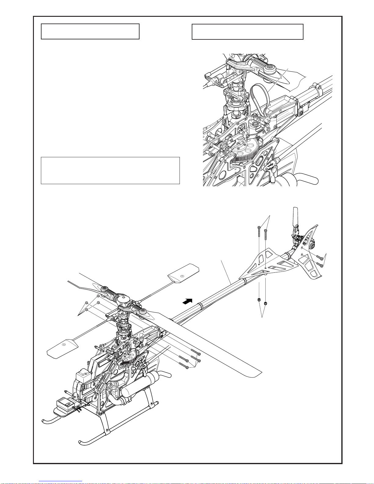
59
VI.テールブームの交換
VI. Tail Boom Replacement
1. はじめに、M3X32CSをゆるめて、テールブームAssyを少し前に寄せて
プーリーからタイミングベルトを取り外します。
At first, remove the timing belt from pulley loosening M3X32CS and moving
the tail boom assembly a little forward.
2. M3X35CSとM3ナイロンナットをはずし、水平尾翼を取り外します。
Unscrew M3X35CS and M3 nylon nut to remove horizontal stabilizer.
3. M3X15CSをはずし、テールケースを引き抜きます。
Unscrew M3X15CS and remove the rod end to take the tail unit case off the
end of tail boom.
4. M3X32CSとM3ナイロンナット薄型をはずし、テールブームを引き抜き
ます。
Unscrew M3X32CS and M3 nylon nut thin type to remove the tail boom.
組み立てるときは、タイミングベルトの回転方向及びねじれに注意
してください。(P27を参照)
When assembling, make sure that the direction of timing belt
rotation is correct. (Refer to Page: 27)
M3X15CS
M3 ナイロンナット
M3 nylon nut
テールブームAssy
Tail boom assembly
M3X35CS
M3X32CS
M3ナイロンナット薄型
M3 nylon nut thin type
タイミングベルト
Timing belt
60
5. 補修パーツについてRepair parts
2004年1月改定
商品合計額
地区
北海道、沖縄、離島
東北
関東、信越、北陸、中部
関西、中国
四国
九州
注文書(コピーしてお使い下さい)
受付No.
年月日
〒-
都・道 郡
府・県 区
() ( )
−
−
−
−
−
①パーツ代金の合計
②消費税(5%)
ヒロボー株式会社(パーツ係)
〒726-0004 広島県府中市府川町138
TEL:(0847)40-0088 (代)FAX:45-7670
http://model.hirobo.co.jp/
③送料(代引手数料込)
お支払金額=商品合計額(①+②)+③
商品合計額(①+②)
¥1,470
ご住所
コードNo
TEL
¥1,050 ¥1,155 ¥1,365
¥1,680
¥1,365
¥1,470
金額品名 単価 数量
希望する・希望しない
市・
FAX
お名前 時間指定
無・有
( 時頃)
ふりがな
ご注文回数 はじめて・2回目以上
¥1,155
¥1,890
日祝日配達
¥1,680
¥1,470
¥1,260
¥1,260
+
=
1万円以上
3万円未満
1万円未満
¥1,155
3万円以上
10万円未満
お申し込み年月日
¥1,575
¥1,365
¥1,155
¥1,050
●補修パーツのご購入につきましては、キッ トを購 入された 模型店へコードNO.と名称を言っ てお買い求め下さ い。
●上記の方法で購入が困難な場合は、直接当社パーツ係まで下記要領にてお申し込み下さい。
商品は宅配便にて、ご注文受付から3日〜7日前後でお届 けい たし ます。
まことに勝 手ながら、 土日祝日、年末年始、GW、お盆休み中のご注文は 、休み明けから3日〜7日前後とさせていただき ます。
また、月初めは棚卸 し のた め1日〜3日ほ ど余分にお時間をいただ く こともあります。 あらかじめご了 承ください 。
商品の不良、配送上の破損、ご注文と違 う 商品が届いた 場合は、お手数ですが商品到着8日以内に
お電話( 0847-40-0088 )パーツ係ま で ご連絡の上、ご返送くだ さ い。返送料は当社で負担いた し ます。
※コードNO、品名は商品に表示してあります。 商品が届いてすぐに商品内容をご確認ください。
お客様のご 都合による返品・交換は受付ておりませんので、コー ドNO、品名、数量をご確認の上、ご注文 ください。
商品のお届け
商品の交換
●お申込は FAX あるいは お電話 にて、お申 し 込 みくだ さい。
●お支払は 代金引換 となります。 商品がお手元に届いた際に、代金を宅急便の方にお支払ください。
商品合計額【①パーツ代金の合計+②消費税(5%)】+ ③送料(代引手数料込み)が必要です。
※なお、現金書留による送金、銀行振込、切手等による代金受付は、現在行っており ません 。ご了承 くだ さ い。
■送料(代引手数料込)※商品合計額とお住まいの地区によって異なります。
(例)北海道にお住まいの方で、パーツ9,800円分ご注文の場合
商品合計額¥10,290 【①パーツ代金の合計¥9,800 + ②消費税(5%) ¥490 】+ ③送料(代引手数料込)¥1,680
=お支払金額¥11,970 となります。
お申込方法

61
2505-007
2532-021
2531-001
2532-031
2525-006
0414-387
2532-021
0414-384
2500-091
2539-009
2532-055
2531-001
0404-347
0404-348(OP)
0404-711(OP)
2532-028
0414-382
0414-390
2500-051
2532-049
2511-032
0414-108
0403-202
2500-090
0414-389
2521-123
2506-041
2506-035
2529-003
2500-061
2521-080
2500-044
2521-124
2532-054
2525-006
2500-073
2521-078
2532-030
0414-383
0414-385
0414-388
0414-283
0414-386
2532-021
2532-040
2539-011
2506-004
2531-003

62
* The prices in parentheses are the prices excluding consumption tax.
コードNo.
Code No.
品名
Part
入数
Q'ty
税込価格
(税抜価格)円
Price (Yen)
備考
Remarks
0403-202
ストッププレート
Stop plate
1
420
(400)
FW付
With FW
0404-347
スタビライザーバーø4X490
Stabilizer b ar ø4X490
2
1,050
(1,000)
0404-348
スタビライザーバーø4X535
Stabilizer b ar ø4X535
2
1,050
(1,000)
0404-711
WC スタビライザーバーø4X555
WC stabilizer bar ø4X555
2
1,050
(1,000)
0414-108
スタビライザーブレード
Stabilizer blade
2
1,890
(1,800)
ストッパー,ネジ付
With stopper and screw
0414-283
EX FRP メインブレード L=680 対称翼
EX FRP main rotor blade L=680 symmet ry
1式
1 set
14,490
(13,800)
0414-382
FFZ-III シーソー
FFZ-III seesaw
1
2,625
(2,500)
ベアリング圧入済
Be
Bearing is sold separately
Bearing is sold separately
aring p re ssed
0414-383
FFZ-III センターハブ
FFZ-III center hub
1
3,990
(3,800)
ベアリング別売
0414-384
FFZ-III フェザリングスピンドル
FFZ-III feathering spindle
1
525
(500)
0414-385
FFZ-III ヨーク
FFZ-III yoke
1
945
(900)
0414-386
FFZ-III ブレードホルダー
FFZ-III blade holder
1
2,100
(2,000)
0414-387
FFZ-III ミキシングアーム
FFZ-III mixing arm
2
525
(500)
ベアリング別売
0414-388
FFZ-III ブレードスペーサー
FFZ-III blade spacer
1式
1 set
525
(500)
t=1.5mm, 2.5mm, 2.8mm
0414-389
FFZ-III ダンパーゴム#60
FFZ-III damper rubber #60
2
1,365
(1,300)
M4X12CS付属
With M4X12CS
0414-390
FFZ-III スタビコントロールアーム
FFZ-III stabilizer control arm
2
730
(700)
2500-044 Brg. ø8Xø16X5 ZZ 2
1,260
(1,200)
2500-051 Brg. ø4Xø8X3ZZ 2
1,260
(1,200)
2500-061 Brg. ø4Xø9X4 ZZ 2
1,260
(1,200)
2500-073 Brg. ø4Xø8X3FZZ 2
1,260
(1,200)
2500-090 Brg. ø5Xø13X4F ZZ 2
1,260
(1,200)
2500-091
Brg.スラスト ø8Xø16X5H
Bearing thrust ø8Xø16X5H
2
1,680
(1,600)
2505-007
M4ナイロンナット
M4 nylon nut
10
210
(200)
2506-004 FW ø3Xø8X0.5T 20
105
(100)
2506-035 FW ø8Xø12X0.1T 10
420
(400)
2506-041 FW ø5Xø12X1.5T 5
630
(600)
2511-032
クロスメンバーM2X109(ø5ボール付)
Cross member M2X109 (with ø5 ball)
2
1,260
(1,200)
2521-078
カラー2.6X4X4F
Collar 2.6X4X4F
2
525
(500)
2521-080
カラー2.6X4X12S
Collar 2.6X4X12S
2
525
(500)
2521-123
カラー4X5X4.3F 7X0.4
Collar 4X5X4.5F 7X0.4
2
525
(500)
2521-124
カラー12X15.9X6.8
Collar 12X15.9X6.8
2
525
(500)
2525-006
EX ø5ボール
EX ø5 ball
10
1,050
(1,000)
2529-003
OリングP-7
O-ring P-7
5
315
(300)
2531-001
セットスクリューM3X3
Set screw M3X3
10
315
(300)
2531-003
セットスクリューM4X4
Set screw M4X4
10
315
(300)
2532-021
キャップスクリューM4X10
Cap screw M4X10
10
630
(600)
2532-028
キャップスクリューM2X8
Cap screw M2X8
10
840
(800)
2532-030
キャップスクリューM2.6X8
Cap screw M2.6X8
10
840
(800)
2532-031
キャップスクリューM2X6
Cap screw M2X6
10
840
(800)
2532-040
キャップスクリューM4X12
Cap screw M4X12
10
630
(600)
2532-049
キャップスクリューM2.6X15
Cap screw M2.6X15
10
840
(800)
2532-055
ドラッグボルトø5
Drag bolt ø5
2
630
(600)
2539-009
ボタンボルトM5X10
Button bolt M5X10
2
315
(300)
2539-011
ボタンボルト M3X8
Button bolt M3X8
2
315
(300)
2532-054
キャップスクリューM2X12 D=3.3
Cap screw M2X12 D=3.3
10
840
(800)

63
2532-031
2525-006
2532-015
0414-230
2531-003
2506-029
0414-391
0404-023
2509-003
2505-001
2532-029
2531-003
0414-114
2532-002
2532-034
0404-118
2506-045
2538-002
0404-805
エンジン(別売)
Engine not
included
2513-053(別売)
not included
0414-111
0414-311
2532-028
2525-006
0403-085
2532-004
2500-072
2500-072
2506-019
2532-021
0414-403 (10T)
0414-374 (12T)
0414-404 (11T)
2500-049
2500-066
0414-307
2529-008
0404-012
2505-001
2532-022
0414-287
0414-392
2532-039
2500-049
0404-616
2500-047
0414-115
2500-102
2500-047
2532-034
2521-053
2532-002
2530-005
0404-531
2530-005
2530-004
2530-004
プロペラナット
(エンジン付属)
2537-001
0404-707
2521-084
Prop nut included
with engine
2539-020
2506-019
2506-019
0414-113
2521-069
YSエンジンの場合
For YS engine
YSエンジンの場合
For YS engine
0414-312

64
コードNo.
Code No.
品名
Part
入数
Q'ty
税込価格
(税抜価格)円
Price (Yen)
備考
Remarks
0403-085
JJ-85 W型ウォッシュアウトコントロールアーム
JJ-85 W -t yp e wash-out control arm
2
367
(350)
0404-012
スタータープーリー座金YS, OS61SX用
Starter pulley washer (for YS, OS61SX)
1
315
(300)
0404-023
ラジアスアーム
Radius arm
2
315
(300)
0404-118
EX クーリングファン
EX cooling fan
1
2,100
(2,000)
0404-531
スワッシュプレートセット
Swash plate set
1
4,725
(4,500)
ピボットボルト付
With pivot bolt
0404-616
オートロ駆動軸
Auto-rotat ion drive shaft
1
2,940
(2,800)
0404-707
EXメインギヤ 95T
EX main gear 95T
1
3,675
(3,500)
0404-805
SX テーパーカラー (OS60 用)
SX taper collar (for OS60)
1
525
(500)
0414-111
ø10 メインマスト P=19 5 L= 220
ø10 main mast P=195 L=220
1
945
(900)
60用
For 60
0414-113
メインギヤ 95T
Main gear 95T
1
840
(800)
60用
For 60
0414-114
セカンドギヤ86T
Second gear 86T
1
420
(400)
カラー、ネジ付
with collar and screw
0414-115
オートロケース
Auto-rotat ion case
1
840
(800)
M2.6X10TS-2(座金付)付属
With M2.6X10TS-2 (with washer)
0414-230
六角スターターカップリング(60〜90 用)
Hexagon starter coupling (for 60-90)
1
1,680
(1,600)
0414-287
エンジンブロック(R, L)
Engine block (R, L )
各1
each 1
1,890
(1,800)
厚さ12mm
Thickness 12mm
0414-307
E3 軸付クラッチシュー
E3 clutch shoe with shaft
1
3,360
(3,200)
0414-311
ø10 メインマスト P=19 9 L= 22 4 ( SU S )
ø10 main mast P=199 L = 22 4 ( SU S)
1
3,780
(3,600)
0414-312
ø10ハードグリップマストロック
ø10 hard grip mast lock
1
1,050
(1,000)
M2.6X6CS付
With M2.6X6CS
0414-374
W Brg付クラッチベル12T
W-brg clutch bell with gear (12T)
1
4,725
(4,500)
80-90用
For 80-90
0414-391
ELS05ウォッシュアウトブロックセット
ELS05 wash-out block set
1 式
1 set
1,050
(1,000)
0414-392
ELS05 フライホイール
ELS05 flywheel
1 式
1 set
3,150
(3,000)
0414-403
W Brg付クラッチベル10T
W-brg clutch bell with gear (10T)
1
4,725
(4,500)
60-70用
For 60-70
0414-404
W Brg付クラッチベル11T
W-brg clutch bell with gear (11T)
1
4,725
(4,500)
70-90用
For 70-90
2500-0 47 Brg. ø12X 21X5ZZ 2
1,260
(1,200)
2500-0 49 Brg. ø10X ø19X5ZZ 2
1,260
(1,200)
2500-0 66 Brg. ø6X ø19X6ZZ 2
1,260
(1,200)
2500-0 72 Brg. ø3X ø7X3ZZ 2
1,260
(1,200)
2500-102
Brg.ワンウェイø12X16L (EWC)
Bearing one-way ø12X1 6L (EWC)
1
1,890
(1,800)
2505-001
M2 ナット
M2 nut
20
210
(200)
2506-0 19 FW ø3X4.5X0.5T 10
210
(200)
2509-003
ニードルピン2X11.8
Needle pin 2X11.8
2
315
(300)
2513-053
ワンウェイスターターシャフトDH
One-way starter shaft DH
1
3,990
(3,800)
エンジン始動用
For engine start
2521-053
カラー3X5X4.1
Collar 3X5X4.1
2
315
(300)
2521-069
カラー3X8X7
Collar 3X8X7
2
315
(300)
2521-084
カラー4X5X4.5S
Collar 4X5X4.5S
2
525
(500)
2525-006
EXø5ボール
EXø5ball
10
1,050
(1,000)
2529-008
O リングSS060
O-ring SS060
5
315
(300)
2530-004
ピボットボルト(D)
Pivot bolt (D)
2
420
(400)
2530-005
ピボットボルト(E)
Pivot bolt (E)
2
315
(300)
2531-003
セットスクリューM4X4
Set screw M4X4
10
315
(300)
2532-002
キャップスクリューM3X8
Cap screw M3X8
10
420
(400)
2532-004
キャップスクリューM3X12
Cap screw M3X12
10
420
(400)
2532-015
キャップスクリューM3X15
Cap screw M3X15
10
420
(400)
2532-021
キャップスクリューM4X10
Cap screw M4X10
10
630
(600)
2532-022
キャップスクリューM4X15
Cap screw M4X15
10
630
(600)
2532-029
キャップスクリューM2X10
Cap screw M2X10
10
840
(800)
2532-031
キャップスクリューM2X6
Cap screw M2X6
10
840
(800)
2532-034
キャップスクリューM3X5
Cap screw M3X5
10
420
(400)
2532-039
キャップスクリューM2.6X6
Cap screw M2.6X6
10
420
(400)
2537-001
座付タッピングスクリューM2.6 X1 0 2 種
Tapping screw with washer M2.6X10 type 2
10
525
(500)
2538-002
サラビスM3X6
Countersunk screw M3X6
10
210
(200)
2539-020
ボタンボルトM4X14
Button bolt M4X14
2
315
(300)
* The prices in parentheses are the prices excluding consumption tax.

65
2532-030
2500-073
2525-006
0404-625
2500-051
0414-394
0414-131
2532-054
0414-127
2521-109
2521-109
2506-020
2525-006
2532-031
2500-050
2505-006
2500-051
2511-029
2506-020
2534-024
2500-057
2500-057
0414-128
2521-039
2500-073
0414-125
2524-001
2532-054
2509-016
0414-132
2521-016
0414-133
2505-006
2531-003
2521-058
0414-393
2532-002
2532-031
0414-126
0404-625
2532-031
2525-006
2534-024
0414-129
2521-083
2500-044
2500-044
2532-008
0414-395
2500-051
2521-125
2532-031
2525-006
2522-029
2522-005
2522-005
2522-029
2522-021
2522-022
2522-014
2522-005
2522-005
2522-021
2524-001
2522-001
2522-008
2537-002

66
コードNo.
Code No.
品名
Part
入数
Q'ty
税込価格
(税抜価格)円
Price (Yen)
備考
Remarks
0404-625
コントロールレバーセット
Control lever set
各 1
each 1
525
(500)
X型レバー(R)(L)各1
X-type lever (R) and (L) each 1
0414-125
コレクトピッチレバー(R)
Collective pitch lever (R)
1
1,260
(1,200)
ベアリング圧入済
Bearing pressed
0414-126
コレクトピッチレバー(L)
Collective pitch lever (L)
1
1,365
(1,300)
ベアリング圧入済
Bearing pressed
0414-127
コレクトピッチシャフト
Collective pitch shaft
1
525
(500)
0414-128
コレクトピッチボルト
Collective pitch bolt
1
420
(400)
0414-129
エルロンレバー
Aileron lever
1
1
525
(500)
ベアリング 別売
0414-131
エレベーターレバーシャフト(R)
Elevator lever shaf t (R)
420
(400)
0414-132
エレベーターレバーシャフト(L)
Elevator lever shaf t (L)
525
(500)
ロールピン付
With roll pin
0414-133
エレベータトルクレバーピボットø4
Elevator torque lever pivot ø4
1
1
525
(500)
SS付
With set screw
0414-393
ELS05エレベーターレバー
ELS05 elevator lever
1
630
(600)
ロールピン付
With roll pin
0414-394
ELS05エレベーターアーム
ELS05 elevator arm
2
630
(600)
0414-395
ELS05 T型ピッチレバー
ELS05 T-type pitch lever
1
525
(500)
ベアリング、カラー別売
2500-044 Brg. ø8Xø16X5 ZZ 2
1,260
(1,200)
2500-050 Brg.ø3Xø8X4ZZ 2
1,260
(1,200)
2500-051 Brg. ø4Xø8X3ZZ 2
1,260
(1,200)
2500-057 Brg. ø3Xø6X2.5F ZZ 2
1,260
(1,200)
2500-073 Brg. ø4Xø8X3F ZZ 2
1,260
(1,200)
2505-006
M3 ナイロンナット
M3 nylon nut
10
210
(200)
2506-020 FW ø5Xø10X1T 20
210
(200)
2509-016
ロールピン ø2X10
Roll pin ø2X10
10
525
(500)
2511-029
クロスメンバーM3X40
Cross member M3X4 0
2
525
(500)
2521-016
カラー4X7X1.5
Collar 4X7X1.5
1
210
(200)
2521-039
カラー4X6X2
Collar 4X6X2
2
420
(400)
2521-058
カラー4X6X5
Collar 4X6X5
2
315
(300)
2521-083
カラー3X5X1
Collar 3X5X1
2
525
(500)
2521-109
カラー 2.6X3X3.4
Collar 2.6X3X3.4
2
525
(500)
2521-125
カラー3X4-6X15.5
Collar 3X4-6X15.5
1
315
(300)
2522-001
アジャストロッドM2X16
Adjust rod M2X16
5
525
(500)
2522-005
アジャストロッド M2X45
Adjust rod M2X45
5
525
(500)
2522-008
アジャストロッド M2X60
Adjust rod M2X60
5
525
(500)
2522-014
アジャストロッド M2X110
Adjust rod M2X110
5
525
(500)
2522-021
アジャストロッド M2X40
Adjust rod M2X40
5
525
(500)
2522-022
アジャストロッド M2X75
Adjust rod M2X75
5
525
(500)
2522-029
アジャストロッドM2X65
Adjust rod M2X65
5
525
(500)
2524-001
M2ロッドエンド
M2 ball link
10
525
(500)
2525-006
EXø5ボール
EXø5 ball
10
1,050
(1,000)
2531-003
セットスクリューM4X4
Set screw M4X4
10
315
(300)
2532-002
キャップスクリューM3X8
Cap screw M3X8
10
420
(400)
2532-008
キャップスクリューM3X25
Cap screw M3X25
10
420
(400)
2532-030
キャップスクリューM2.6X8
Cap screw M2.6X8
10
840
(800)
2532-031
キャップスクリューM2X6
Cap screw M2X6
10
840
(800)
2532-054
キャップスクリューM2X12 D=3.3
Cap screw M2X12 D=3.3
10
840
(800)
2534-024
タッピングスクリューM2.6X8 2 種
Tapping screw M2.6X8 type 2
10
210
(200)
2537-002
座付タッピングスクリューM2.6X16
Tapping screw with washer M2.6X16
10
525
(500)
Bearing and collar are sold separately
ベアリング、カラー別売
Bearing and collar are sold separately
Bearing is sold separately
* The prices in parentheses are the prices excluding consumption tax.

67
0414-293
0414-292
0404-675
2532-006
0414-293
2505-020
2505-020
2536-001
0414-284
2505-020
2505-020
2511-020
2511-003
2532-053
2511-020
2532-053
2532-015
2532-004
2532-004
2532-004
2532-002
2532-004
2532-004
0414-398
0414-398
2532-004
2523-051
2532-004
2532-015
2505-019
2523-051
2505-019
0404-696
0414-285
0414-286
2523-051
0414-286
2505-019
2532-038
2523-051
2511-007
2511-007
0402-639
2523-021
0402-639
2505-006
2505-006
2506-010
2505-006
2506-010
2505-006
2506-010
2532-015
2532-015
2532-004
0414-284
0414-399
2532-002
2532-004
0414-399
0414-284
2505-020
2506-010
2505-020
0414-284
2536-001
0414-123(option)
0414-124(option)
0414-124
(option)
0414-397
0414-284
2536-001
0414-284
0414-123
(option)
0414-396
2506-004

68
コードNo.
Code No.
品名
Part
入数
Q'ty
税込価格
(税抜価格)円
Price (Yen)
備考
Remarks
0402-639
スキッドパイプキャップø8
Skid pipe cap ø8
4
315
(300)
0404-675
燃料タンクキャップ
Fuel tank cap
1
630
(600)
SUSパイプ付
With SUS pipe
0404-696
EXスキットパイプ
EX skid pipe
2
1,575
(1,500)
キャップ付
With cap
0414-123
キャビンクロスメンバーM3X34.5
Cabin cross member M3X3 4. 5
2
525
(500)
金属製(オプション)
Metal made (Option)
0414-124
キャビンクロスメンバーM3X43
Cabin cross member M3X4 3
2
525
(500)
金属製(オプション)
Metal made (Option)
0414-284
キャビンクロスメンバーセット
Cabin cross member set
1 式
1 set
735
(700)
ネジ付
With screws
0414-285
ローハイトランディングギヤAssy
Low height landing gear assembly
1 式
1 set
2,835
(2,700)
0414-286
ローハイトスキッドフット
Low height skid foot
2
1,575
(1,500)
0414-292
E3燃料タンク(600cc)
E3 fuel tank (600cc)
1 式
1 set
2,100
(2,000)
0414-293
E3タンク防振ゴム
E3 fuel tank rubber cushion
1 式
1 set
1,050
(1,000)
0414-396
ELS05スイッチプレート
ELS05 switch plate
1
525
(500)
0414-397
ELS05メカマウント
ELS05 mechanical mount
1 式
1 set
840
(800)
ネジ付
With screws
0414-398
ELS05メインフレーム
ELS05 main frame
1 式
1 set
2,625
(2,500)
ネジ付
With screws
0414-399
ELS05サーボフレーム
ELS05 servo frame
1 式
1 set
3,150
(3,000)
ネジ付
With screws
2505-006
M3ナイロンナット
M3 nylon nut
10
210
(200)
2505-019
M2.6ナイロンナット
M2.6 nylon nut
10
315
(300)
2505-020
M3ナイロンナット 薄型 黒
M3 nylon nut (thin type)
10
315
(300)
2506-010 FW ø3Xø9X1T 20
105
(100)
2511-003
クロスメンバーM3X26
Cross member M3X2 6
2
525
(500)
2511-007
クロスメンバーM3X64
Cross member M3X6 4
2
525
(500)
2511-020
六角クロスメンバーM3X46
Hexagon cros s member M3X46
2
525
(500)
2523-021
P.P.パイプø3.5Xø4.5X1100
P.P. p ipe ø3.5Xø4.5X1100
2
420
(400)
2532-002
キャップスクリューM3X8
Cap screw M3X8
10
420
(400)
2532-004
キャップスクリューM3X12
Cap screw M3X12
10
420
(400)
2532-006
キャップスクリューM3X20
Cap screw M3X20
10
420
(400)
2532-015
キャップスクリューM3X15
Cap screw M3X15
10
420
(400)
2532-038
キャップスクリューM3X18
Cap screw M3X18
10
420
(400)
2532-051
キャップスクリューM2.6X10
Cap screw M2.6X10
10
420
(400)
2532-053
キャップスクリューM3X32
Cap screw M3X32
10
420
(400)
2536-001
タッピングスクリューM3X8
Tapping screw M3X8
10
105
(100)
* The prices in parentheses are the prices excluding consumption tax.

69
2506-005
2507-001
2507-001
2507-001
2500-061
2500-062
2500-070
2506-003
0404-662
2532-028
2532-005
0414-119
0414-118
0402-523
2500-068
2521-082
2509-015
0414-146
2534-014
2534-006
0414-135
2537-002
2500-054
2506-029
0414-163
(スライド軸とセット)
(M6 nut included with slide shaft)
2532-030
2500-068
2521-061
0414-143
2509-015
0414-401
2504-027
2505-020
0412-157
0412-147
2525-006
2532-031
2506-005
2539-015
2509-012
2509-012
0414-141
0404-662
2521-079
2500-054
2532-030
0414-401
0414-119
0414-144
2500-068
2532-015
2532-015
2506-021
2506-021
2505-006
2531-002
0404-662
2505-001
2505-006
内径/大
内径/小
Inside dia. :Large
Inside dia. :Small
2532-028
2525-007
2505-006
2506-004
0414-165
2509-015
0414-137
2532-005
0414-142
0414-164
0414-136
2522-001
2522-001
0414-400
2500-051
2500-051
2509-014
2509-014
0414-163

70
コードNo.
Code No.
品名
Part
入数
Q'ty
税込価格
(税抜価格)円
Price (Yen)
備考
Remarks
0402-523
SF Brg.ホルダーø13
SF bearing holder ø13
1
420
(400)
ベアリング別売
0404-662
テールブレードホルダーセット
Tail rotor blade holder set
AB各2
A, B each 2
525
(500)
0412-147
SDテールピッチレバーセット
SD tail pitch lever set
1式
1 set
1,050
(1,000)
0412-157
テールピッチレバーカラー
Tail pitch lever collar
1
525
(500)
0414-118
カウンターギヤシャフト
Counter gear shaft
1
735
(700)
ロールピン付
With roll pin
With roll pin
0414-119
テールプーリー18T
Tail pulley 18T
1
630
(600)
ロールピン付
0414-135
ラダーサーボマウント
Rudder servo mount
1
1,050
(1,000)
ネジ付
With screws
0414-136
ラダーコントロールロッド ø5 L=730
Rudder control rod ø5 L=730
1式
1 set
1,260
(1,200)
組立済
Assembled
0414-137
ラダーコントロールガイド
Rudder control guide
1式
1 set
525
(500)
ネジ付
With screws
0414-141
テールピッチプレートボス
Tail pitch plate boss
1
525
(500)
0414-142
テールピッチリンクセット
Tail pitch link set
1式
1 set
525
(500)
テールピッチプレート、平行ピン付き
With tail pitch plate, parallel pin
0414-143
テールシャフト
Tail shaft
1
735
(700)
ロールピン付
with roll pin
0414-144
テールプーリーシャフト付き
Tail pulley with shaft
1
1,260
(1,200)
組立済
Assembled
0414-146
八角テールブームパイプL=805
Octagonal tail boom pipe L=805
1
1,575
(1,500)
0414-163
スライド軸
Slide shaft
1
420
(400)
M6ナット薄型付
With M6 nut shin type
0414-164
テールハウジング
Tail housing
1
840
(800)
0414-165
対称テールブレード L=92
Symmetrical tail blade L=92
2
525
(500)
0414-400
カウンターギヤプーリーセット18T
Counter gear pulley set 18T
1 式
1 set
1,890
(1,800)
0414-401
ELS05テールユニットケースR/L
ELS05 tail unit case R/L
1式
1 set
1,050
(1,000)
2500-051 Brg. ø4Xø8X3ZZ 2
1,260
(1,200)
2500-054 Brg. ø6Xø10X3ZZ 2
1,260
(1,200)
2500-061 Brg. ø4Xø9X4ZZ 2
1,260
(1,200)
2500-062
Brg. ø4Xø9X4Hスラスト
Brg. ø4Xø9X 4H thrust
2
1,260
(1,200)
2500-068 Brg. ø5Xø13X4ZZ 2
1,260
(1,200)
2500-070 Brg. ø3Xø9X3OP 2
1,260
(1,200)
2504-027
タイミングベルト60S3M1800
Timing belt 60S3M1800
1
1,890
(1,800)
2505-001
M2ナット
M2 nut
20
210
(200)
2505-006
M3ナイロンナット
M3 nylon nut
10
210
(200)
2505-020
M3ナイロンナット 薄型 黒
M3 nylon nut (thin type)
10
315
(300)
2506-003 FW ø3Xø6X0.5T 20
105
(100)
2506-004 FW ø3Xø8X0.5T 20
105
(100)
2506-005 FW ø4Xø6X0.5T 10
105
(100)
2506-029 FW ø6Xø8X0.3T 5
525
(500)
2507-001
E-リングø1.5
E-ring ø1.5
10
105
(100)
2509-012
ミゾ付平行ピン2X11.6
Grooved parallel pin 2X11.6
2
315
(300)
2509-014
ロールピンø2X5
Roll pin ø2X5
10
525
(500)
2509-015
ロールピンø2X12
Roll pin ø2X12
10
525
(500)
2521-061
カラー5X8X2.5
Collar 5X8X2.5
2
315
(300)
2521-079
カラー6X7X3
Collar 6X7X3
2
525
(500)
2521-082
カラー5X6.5X14
Collar 5X6.5X14
2
525
(500)
2522-001
アジャストロッドM2X16
Adjust rod M2X16
5
525
(500)
2525-006
EX ø5ボール
EX ø5 ball
10
1,050
(1,000)
2525-007
EX ø5ボール 台付
EX ø5 ball with stand
10
1,050
(1,000)
2531-002
セットスクリューM3X5
Set screw M3X5
10
315
(300)
2532-005
キャップスクリューM3X16
Cap screw M3X16
10
420
(400)
2532-015
キャップスクリューM3X15
Cap screw M3X15
10
420
(400)
2532-028
キャップスクリューM2X8
Cap screw M2X8
10
840
(800)
2532-030
キャップスクリューM2.6X8
Cap screw M2.6X8
10
840
(800)
2532-031
キャップスクリューM2X6
Cap screw M2X6
10
840
(800)
2534-006
タッピングスクリューM2.6X12 2 種
Tapping screw M2.6 X12 N o.2 type
10
105
(100)
2534-014
タッピングスクリューM3X12 2 種
Tapping screw M3X12 No.2 type
10
210
(200)
2537-002
座付タッピングスクリューM2.6X16
Tapping screw with washer M2.6X16
10
525
(500)
2539-015
ガイドピン M3X6.3
Guide pin M3X6.3
2
525
(500)
Bearing is sold separately
* The prices in parentheses are the prices excluding consumption tax.

71
2532-012
0414-405
0414-407
0414-406
0414-208 (option)
0414-150
0414-402
2505-013
2505-006
2532-049
0412-166
2532-002
2506-010
0414-147
2506-010
2532-015
2505-006
0414-149
0414-148
2534-013
0414-173 (option)
0414-174 (option)

72
コードNo.
Code No.
品名
Part
入数
Q'ty
税込価格
(税抜価格)円
Price (Yen)
備考
Remarks
0412-166
キャビンダンパーゴム
Damper rubber for cab in
4
420
(400)
0414-147
キャビン
Cabin
1
3,675
(3,500)
ダンパーゴム付
With damper rubber
0414-148
キャノピー
Windshield
1
1,050
(1,000)
0414-149
尾翼セット
Tail stabilize set
1 式
1 set
1,575
(1,500)
ネジ付
With screws
0414-150
水平尾翼バンド
Horizontal fin band
1 式
1 set
525
(500)
0414-173
Freya WCデカール
Freya WC decal
1 式
1 set
2,625
(2,500)
0414-174
Freya ロゴデカール
Freya logo decal
1 式
1 set
2,625
(2,500)
オプション
Option
0414-208
Freya WCデカール(尾翼用)
Freya WC decal for tail stabilizer
1
2,100
(2,000)
0414-333
EAGLE3デカール
EAGLE3 decal
1
3,675
(3,500)
オプション
Option
0414-334
EAGLE3デカール(尾翼用)
EAGLE3 decal (for tail stabilizer)
1
2,730
(2,600)
オプション
Option
0414-402
ELS05テールブームブレースセットL=560
ELS05 tail boom brace set L=560
1 式
1 set
1,575
(1,500)
0414-405
FREYA EVOデカール
FREYA EVO decal
1 式
1 set
3,150
(3,000)
0414-406
FREYA EVOデカール(尾翼用)
FREYA EVO decal for tail stabilizer
1
1,575
(1,500)
0414-407
FREYA EVO説明書
FREYA EVO instruction manual
1
2,100
(2,000)
2505-006
M3ナイロンナット
M3 nylon nut
10
210
(200)
2505-013
M2.6ナット
M2.6 nut
20
210
(200)
2506-010 FW ø3Xø9X1T 20
105
(100)
2532-002
キャップスクリューM3X8
Cap screw M3X8
10
420
(400)
2532-012
キャップスクリューM3X35
Cap screw M3X35
10
420
(400)
2532-015
キャップスクリューM3X15
Cap screw M3X15
10
420
(400)
2532-049
キャップスクリューM2.6X15
Cap screw M2.6X15
10
840
(800)
2534-013
タッピングスクリューM2.6X6 2 種 トラス
Tapping screw M2.6X6 No.2 type truss
10
210
(200)
0414-333 (option) 0414-334 (option)
* The prices in parentheses are the prices excluding consumption tax.

73
○○ ○
○○
オフセット量
スイッチ:
スイッチ:E
ラダーオフセット量
ホールドポジション
スイッチ:
Cond
Switch:
Cond
機能のACT/INH
ACT
ラダーオフセット
FUTABA FF9-H
GYRO
TH-HLD
PI-CRV
TH-CRV
TH-CUT
Function ACT/INH
Offset
amount
-20%
REVERSE
F/S
EXP
D/R
(R/U)
(L/D)
NORM
IDL1
IDL2
IDL3
NORM
IDL1
IDL2
IDL3
100%
1ch(AIL)
100%
70%
100%
100%
100%
0%
0%
0%
0%
NORM NORM NORM NORMREV REV
100%
2ch(ELE)
100%
110%
3ch(THR)
60%
-----
-----
-----
-----
-----
-----
25%
70%
90%
80%
100%
0%
0%
0%
0%
120%
4ch(RUD)
120%
100%
5ch(GYR)
100%
100%
6ch(PIT)
80%
90%
100%
100%
100%
0%
-50%
-50%
-50%
(NORM)
(F/S)
END POINT
ACT
NORM
IDL1
IDL2
IDL3
HOLD
NORM
IDL1
IDL2
IDL3
NORM
POS1
IDL1
IDL2
IDL3
HOLD
35%
35%
30%
0%
0%
70%
100%
100%
20%
POS2
54%
45%
40%
20%
42%
65%
85%
75%
40%
POS3
68% (60%)
55%
50%
50%
50%
70%
80%
65%
60%
POS4
80%
72%
65%
75%
65%
80%
85%
80%
80%
POS5
90%
90%
85%
95%
100%
100%
100%
100%
100%
AVC
Switch:E
Cond
Switch:
Cond
NOR
NOR
AVC
NOR
100%
60%
60%
60%
90%
OFST-1
OFST-2
OFST-3
ACT
ACT
ACT
0% -10%
Hold position Rudder offset amount
Rudder offset
ACT
0%
0%
0%
0%
0%
AIL ELE RUD
0%
INH
GY601 is used for the gyro.
※3. オフセットは実際の飛行に合わせて調整して下さい。
Adjust the offset by actual flight.
※2. ピッチカーブの( )内は0404-808 WCメインブレード又は、0404-809 EXメインブレード使用時のものです。
The data shown in pitch curve parentheses indicate values for when the 0404-808WC or the 0404-809EX main blades are used.
※4. 各コンディションは以下のような設定になっています。
Each condition is set as follows.
IDL3
HOLD
オートローテーション
Autorotation
IDL2
ロール系
Roll
IDL1
ループ系
Loop
3D
※1. ジャイロはGY601を使用しています。
NORM
ホバリング
Hovering

74
80%
AILE
80%
ELEV
90%
80% 80% 90%
LIN LIN LIN
LIN LIN LIN
110% 90% 100%
110% 90% 100%
LIN LIN 50%
LIN LIN 50%
120% 100% 120%
120% 100% 120%
LIN LIN 50%
LIN LIN 50%
RUDD
NORM
ST-1
ST-2
ST-3
ST-4
HOLD
NORM
ST-1
ST-2
ST-3
ST-4
HOLD
0
1
1
1
0
0
0
1
1
1
0
0
0
1
1
1
0
0
NORM
ST-1
ST-2
ST-3
ST-4
HOLD
NORM
ST-1
ST-2
ST-3
NORM
HOLD
ST-1
ST-2
ST-3
ON
ON
ON
ON
ON
OFF
ON
ON
ON
0
1
1
1
0
0
1
2
100%
60%
60%
POS-0
POS-2
POS-0
POS-2
INH
POS-0
AUT
D/R
THROTTLE
HOLD
0
D/R
EXP
D/R
EXP
D/R
EXP
THRO AILE
EXP
0
72
100
100
35
20
30
25
0
L
30
INH
85
80
INH
INH
INH
INH
INH
1
45
INH
INH
70
INH
INH
INH
INH
INH
2
50
68
82
68
68 (60)
60
55
50
50
3
INH
75
INH
75
INH
INH
INH
INH
INH
4
70
INH
85
INH
INH
INH
INH
INH
INH
5
100
100
100
100
90
100
90
82
95
H
ELEV RUDD GEAR PIT
REV NORM REV NORM NORM NORM
H 90% L 100% D 100% L 140% + 0% H 140%
L 60% R 100% U 100% R 140% - 150% L 120%
F/S HOLD HOLD HOLD HOLD HOLD
REVERSE SW
TRAVEL ADJUST
FAIR SAFE
THRO
CURVE
PITCH
CURVE
1
2
JR PCM9X
SWASH MIX
RUDD D/R
GYRO SENS
TYPE
ACT
POS
5%
1S
DUAL RATE EXP
A.D.T
G7000T is used for the gyro.
※3. オフセットは実際の飛行に合わせて調整して下さい。
Adjust the offset by actual flight.
※2. ピッチカーブの( )内は0404-808 WCメインブレード又は、0404-809 EXメインブレード使用時のものです。
The data shown in pitch curve parentheses indicate values for when the 0404-808WC or the 0404-809EX main blades are used.
※4. 各コンディションは以下のような設定になっています。
Each condition is set as follows.
ST-3
HOLD
オートローテーション
Autorotation
ST-2
ロール系
Roll
ST-1
ループ系
Loop
3D
※1. ジャイロはG7000Tを使用しています。
NORM
ホバリング
Hovering

75
SANWA STYLUAS
1) スロットル 2) エルロン 3) エレベータ 4) ラダー 5) ジャイロ 6) ピッチ
REV
REV REVNOR NOR NOR NOR
1) Throttle 2) Aileron 3) Elevator 4) Rudder
Aileron Elevator Rudder
5) Gyro 6) Pitch
(H/L/D) 90% 100% 100% 140% 140%
(L/R/U) 60% 100% 100% 140% 120%
F-SAFE 10% INH INH INH INH INH
エルロン エレベータ- ラダー
GYRO
12
80% 80% 100% N 90%
80% 80% 100% 1 55% 60%
55% 60%
55% 60%
100% 80% 110% 2
100% 80% 110% 3
100% 80% 90% 4 90% 90%
60%
100% 80% 90%
100% 100% 110%
100% 100% 110%
80% 80% 100%
80% 80% 100%
N0%0%0%
10%0%20%
2
0% 0% 20%
3
0% 0% 20%
4
0% 0% 0%
N0%0%0%
10%
20%
3
0%
0%
0%
0%
0%
0%
0%
0%
40%0%
PL P1 P2 P3 PH
N レート 35% INHRate
Rate
Rate
Rate
Rate
Point
Point
Point
Point
Rate
Rate
Rate
Rate
68% (60%) INH 90%
1
レート 30% INH 55% INH 90%
2
レート 25% INH 50% INH 82%
3
レート 0% INH 50% INH 95%
4
レート 20% INH 60% INH 100%
ポイント 50%
レート 0% 50% 100%
ポイント 25% 50% 75%
レート 75% 65%
25%
40%
68% 80%
INH
75%
65%
100%
ポイント 25% 50% 75%
レート 100% INH 80% 100%
ポイント 25% 50% 75%
レート 100% INH 70% INH 100%
SG-11 is used for the gyro.
※3. オフセットは実際の飛行に合わせて調整して下さい。
Adjust the offset by actual flight.
※2. ピッチカーブの( )内は0404-808 WCメインブレード又は、0404-809 EXメインブレード使用時のものです。
The data shown in pitch curve parentheses indicate values for when the 0404-808WC or the 0404-809EX main blades are used.
※4. 各コンディションは以下のような設定になっています。
Each condition is set as follows.
3
4
オートローテーション
Autorotation
2
ロール系
Roll
1
ループ系
Loop
3D
※1. ジャイロはSG-11を使用しています。
N
ホバリング
Hovering
1
N
2
TH
CURVE
PIT
CURVE
3
4
EXP
OFF SET
EPA
2
D/R
N
1
3

MEMOMEMO
MEMOMEMO
MEMO

MEMOMEMO
MEMOMEMO
MEMO

MEMOMEMO
MEMOMEMO
MEMO

①本書の内容の一部または全部を無断で転載することは禁止されています。
②本書の内容については、将来予告なしに変更することがあります。
③本書の内容について万全を期しておりますが、万一ご不審な点や誤り、記載もれなどお気付
きのことがありましたら、ご一報くださいますようお願いいたします。
④運用した結果については③項にかかわらず責任を負いかねますので、ご了承ください。
①Reproduction of this manual, or any part thereof, is strictly prohibited.
②The contents of this manual are subject to change without prior notice.
③Every effort has been made to ensure that this manual is complete and correct. Should there,
however, be any oversights, mistakes or omissions that come to your attention, please inform
us.
④Item ③ not withstanding, we cannot be responsible for events related to the operation of your
model.
注意 Note
平成17年5月
First printing
初版発行
May 2005
138 FUKAWA-CHO, FUCHU-SHI,
HIROSHIMA-PREF., JAPAN. 〒726-0004
TEL:0847-40-0088 FAX:0847-45-7670
http//model.hirobo.co.jp/
広島県府中市府川町
138 〒726-0004
TEL:
(0847)40-0088
(代)
FAX:45-7670
http://model.hirobo.co.jp/
 Loading...