


HlROecl
'il
Single-rotor
Electric
RC Helicopter
00 Belore Operatiig
.
P1
0r selcontenls.
. .. .
P4
02
LJs
ng lhe L lhium Poymer Balrery
and Spec a PurposeCharger
''
P5
03 Us
ng the Transmner'
.
- .
P7
04 Us ng the ConirolUnt
. . .
P9
0s Affx deca s
Pio
06
lmage Training
.
. . .
P]1
07 Fight Preparatons
.
.. .
P12
071. Alta.hrng and Remov ng tlre
Cab n
. .
. .P12
07 2 nslal ng th. B-liery
P12
07 3
Procedurr ioi
ON,OFF Power wiiches
. . . .
Pl3
07.1 Prei
ehl
.ipeclon
P14
This
product
is
nol inlended lor children.
To ensure lhesaie use olthis
product. please
be sure to read the instruction manualcarelully berore
use.
n
llllitF
0a 1 Tai n! .ii a s ngle rot.r lre
copler
' .
P16
03 2
Tfr.(r:tcl
operatio.s
practi.e
.
P17
08.3
Pra.:.f!
'udderoperaton
... . ..
P18
031 Pra.i..q hoverng.
.
Plg
0aJ Pra.ic.g hor zoftal movement
- ..P20
aa 6 Pracoci.q
pioue1ies.
P2l
09 Lrri I Lle n(e.a.ce
P22
09 : F3pacinq the man blad
P22
09-2. Fepacng thela blade.
. -- -
P22
09-3. Track rg adlu shenl
. . . - -P23
09
4 A
eron and eelaror trm adjushenr
. . .- -
P24
095 Fudderirim adllshenl
..- - -
P26
09 6 Adjustng the rolation
speed olthe main blade
.
P27
10 Using a Commerc a Transminer'
- -- -
P2a
i1CheckpointsiorFyn9Probens.
. . . - -
P3l
12 Dsassemb
rg and reassembing lhe ilying Lnt
. - - -
P32
12 1
Genera
g!
de lnes on d sassemblfg the iying u.il
- -
P32
122 Botorhead.
. .
...
P33
l2-3. Frame and molor
P34
12,1.Ta1
. . . ...
.......P35
13 Pans L sl
P36
l,1Expert
ele r Us .g the optiona iealures
. . -P38
14 i. Cha.g ng lhe aie.on
a.d e evatof.udder ang es
-
P3a
14-2.Adj!sting rhe throtle
cu
.
.
P39
1.1 3. Adjusti.g rudder
rotal on speed
. .
P40
i4 4 Adjusting lhe
gyro
sens tvity
.
.--
P41
i4 5 Adjust ng the
subt. ms
. . . .
P42
146 Fesetlngtlredata...
..- - - -P42
Furcion Lst and Ercr D
spay Lsl.
. .
P43
rlillil
I
No I0897

Singl+rorqr
Electric RC Helicopler
The
S.R.B. Quark offers to those who
have mastered hovering with lhe X.R.B.
co-axial counter-rotating indoor
electric RC helcopter, an
even
higher
level oi ireedom of flight control, while
the design ensures
greaier
safety
an0 ease ol use.
The
S.R.B.
Quark
employs
a single rotor systern,
yet
it has the man
rotor and ihe tail rotor
just
ike
general
helicopters,
providing
a more realistic
helicopter style. At lhe same
time, ts design oifers the most
superior
slability and excellent conirollability
among the single-rotor RC he icopters.
Athough the S.R.B.
Quark ofiers the most superior stability
and excellent controlabiljty among lhe
single-rotor
RC helicopters, due to the
characterlstic ieaiure oi a single rotor he icopter,
S.R.B
Quarks
steering will feel
mofe sensitive than co
axial counter-rotaling helicopters like X.R.B,
and it requires more stck
operation to
control lake-ofi or
pirouettes.
Please
read these inslructions
carelully n order lo master the handling
ol this
helicooter.
lJ
you
can masler the
S.F.B. Quark,
you
will have reached a level wheTe
even RC helicopters aimed
at expefts
will
be within
your
abilily to control. We
hope thal this will be
your
first
step
inio
the wonderful world of FC
he icoPiers.
Main
Specifications
Body
Fuselage
ength 350mm
Fuselaoe width
7zmm
Overa I heiqht
'146mm
Main rotor dia.
355mm
Tail rotor dia. 106mm
Overa I weioht 17Og
Gear ralio
Main blade
Tail blade
5.29 : 1
411
Max mum Flioht Time Approx. 10
minutes
Lithium-polymer battery
Vo laqe
Capacily 480mAh
Batterv
Charqer
Inpul DC12-24V
Output 8.4V 0.65A
cnarger
AC oower sr adapter for
balte
Input
AC100V-240V 50-60H2
OLrlput DCl5V 14

Thank
you
for
your purchasing
of a HIROBO
product.
To ensure saiety,
please
read
this manualthoroughly
before flying the model.
We request thal
you
make
yourself
familiar with the
cautions, the llying the capacity
ol this model
plane,
how to fly
ii, and use of lhis
product
while
observing saieiy rules
and flying manners.
This
instruction manual must
be looked atter and kepl where
it is readilv retrievable.
Product speciiications,
prices,
shapes eic. may
change for improvements wilhout
prior
notice.
AWarning
SNeve.
leave
equipment such as the transmitter,
dry battery, battery
pack,
special-purpose
charger or
flying
unit in a location that
can be accessed by the inquisitive
hands of infants
or children. They
can
accidentally
activate operation,
or
put
the battery or
small
parts
in their mouth;
any of such actions
^
could resull
in iniury or damage
caused by chemical
substances.
\)Never
disassemble
or attempt to modify
anylhing other that what
is specified in this manual.
^
Doing so
could cause eleciric shock,
an injury, equipment
breakdown or a subsequenl
tire.
NNever
store the transmitler,
battery. special-purpose
charger, or tlying unit in
lhe following
placqs.
Storing such equipment in these
places
could
cause shape alistortion, breakdown
and subsequent
injury
or
fire
as a direct result
of equipment breakdown.
.
Hot
places
that
exceeal 40
"C
or cold
Dlaces that fall below
-10
.C
.
Places
exposed to direct sunlight
.
Places with high humidity,
vibration,
or
lols
of dust
.
Places with moisture
or steam or where
exposed to a source
of
heat
S
Never fly ihis
product
in the following
places.
Jammed electrical
signals, incorrecl
operation, or malfunctions in
either the transmiller
or main unit
may cause the flying
lrnit to crash,
possibty
colliding with
peopte
or obiects and
causing injury 6r
damage. ln addition, moisture,
sand or dust may
cause the
product
to matfunction.
'ln
strong winds,
rain, snow, thunder
or other bad weather
.
At night, when the flying
unit is difiicult
to see
.
Near buildings,
roads, railways,
power
lines or airports
.
In crowded
areas, or around
children or
pets
.
In small rooms,
or near furniture
_
.
When remotecontrolled
models using
the same lrequency
are nea6y
lpAlways only use
lhe
genuine
Hirobo
battery and chargei
(tor
S.R.B). If a non-genuine
part
is used,
Hirobo
will not be liable for
any loss that
arises out of such use.
Use only iiems that
are
tisted
in this
inslruction
manual.
QAlways
refrain from
flying units that
use the same radio Irequency
at the same
time. The radio signal
interference may
cause a ctash.
*
The radio signal interference
will still happen
when the radio frequency
is the same
even if a different
_
moclulation
type is used
(AM.
Flr. PCM etc).
QAlways
refrain
irom touching
pans
that are insta
ect
in
the ftying unit, namely
the motor,
pinion
gears,
motor mounting
screws and connectors
during use
or directty after use. These
parts
heai up to high
temperalures
and can cause burns.
a
An
explanation of the
safety symbols used in this manual
This manual conta ns
safeiy symbols to warn
the readef of
jtems
that requke
partjcular
atteniion to
safety.
The meanings
of these safety symbols
are
given
below.
AWaf
ninq
lwarning
symbol] lf
you
handle
the
product
in a way
that ignores the warning
information
highlighted
by this symbol, it could resu[ in
a fatal or serious
inlury to
the user or a bystander
or lhere is a high
possibility
that a minor
inlury or some kind
of
property
damage
coutd occur.
ACaUtiOn
lcaution.symboli.lf.
you
handle
the
product
in a way that ignores
lhe caution
information
highlighted by this
symbot, it could resuli in
an
injury
to the user
or a bystander
or there is a
possibility
of some kind of
property
damage.
S
lprohibited
actionl The
prohibited
action
symbol
identifies
acts that never
should be
Derlormed.
O
lessenlial
practic.f
;lf;""ii"r
o,""tice
symbol identities
practice
rhar must
atways be

ACaution
O
Never attempt to modify the
product.
lt may
cause a breakdown.
$
Never
put
your
hands or face
close to
rolating
parts.
Doing so creates the risk of unexpected injury.
*
When flying the
unil
indoors
or when adiusting it while holding it in
your
hands, we recommend
wearing
proleclive
eyeglasses.
OTo
avoid such risk, never operate this
product
while
sitting on
the Iloor
or on a chair. Operate this
product
in a
posture
that allows
you
lo
quickly
get
oul of
the way if
necessary.
OAlways
power
switch off both the flying unit and transmitler when leaving the transmitler
unattended.
lf the
power
switch is left
on,
it is
possible
that unintended stick operation occurs when the transmitter
is
placed
on the floor
or a chair.
S
Never hang the
cord around
your
neck. Doing so creates the risk of strangulation.
S
Never allow
young
children to use ihis
product.
Doing so creates the risk
of accident caused by
rolating
pa
s or the cord,
QAlways
use this
product
in a way thal is
proper
and safe
to mainlain its
performance.
To do this
you
musi read this instruction manual lhoroughly. This
product
is
a
precision
machine
that can easily be
broken
iI
dropped or used
incorrectly.
$To
ensure safe
practice,
never use
parts
that are damaged or have altered shape in this
product.
Qntways
pay
attention to the fact that much functionality is required of this
product's parts
and
parts
;nclude small
items,
sharp items and items made lrom metal. Prevent any
possibility
of a small child
putting
these
parts
in lheir mouth or
qetting
injured by these
parts.
lf a child swallows a
part,
seek
urgenl medical advice. Always discard the
packaging
of the
parts
in a
place
oul of reach of children.
No
pets
around
No waier or
morsiure
When €mole-conlroled
models using the same
nequency arc
neaDy
aroun0
No tab es, cha rs &
other furniture
modifcations
Near bL dings, roads,
la ways,
power
lines
0rarrc0ns
=
For
details, see
"Warning"
and "Caution" sections.
=
In slrong w nds, ran,
other bad
weather
,li'L;!\\:,,;
Keep
away
from
rotating
parts
Avoid f re
&
other
heat
Y,,4
ouard aga nsl cord dariage
2

Secure
the f light
area.
Names
of each component
Allow a minimum
of three meters of clear space
arornd
yoLr<elf
in
all direclions.
lf
Lhete s an
obstruclion
nearby
such as walls or furniture, lhe
SKY
BOBO wil
be ordwn [o lhe obs.rLLton
As
you
ga
n experlence,
you
should still
practice
keeping a safe area.
Never ily this
product
in the foLlowing p aces.
In strong wnds, rain, snow, thunder
or other bad
At nighl, when the fy ng
unit
is
diff cult to see
Near buildings, roads, railways,
power
Ines
or
airports
$
1n
crowded areas, or around children or
peis
QWhen
remote-controlled models using the same
requency are nearby
P ease read Page 1 for further details, and focus
on
flying
safely.
While
get(ing
used to ihe
controls,
we
advise flyjng
when there are no or light winds.
Furlhermore, control
becomes
very
difficu t when the
wind speed is 3 m
or
more. Please
do not attempt
to fly this unit in high winds.
ACaution
lf other
people
are using
wireless
refiote-
controlled models nearby,
be sure to check
which lrequency
they are using. Also, be sure to
tell others which
band
you
are using.
Attempting to use the
same band at lhe same
time may lead to improper
operation and is
extremely dangerous.
Tailfin
lF
lir,,lltl}
hll"lf ilt'll{llli,il.l'
lf
you
are unable to secure.enough flight
area in
your
house,
or
you
would like to learn more about
operat
ng XFIBS,
please
visit our website at http://model.hirobo.co,ipl
The
Shop Inlo.
page
shows
you
XFB flight afeas
and
shops located all over Japan ihat are ready to
provide you
with instruclions.
Tailblade
Main blade
Stabilizer
Tai
pipe
Main mast
Swash
plate
Tailmotor
Ivlarn motor
S-R.B. controlunit
Lithium
polymer
battery

Check thal the following
components
are included.
lFull
set
I
Set
without
the
programmable
transmitter
Do notthrow
away lhe box containing
your
set or lhe blister
package
containing
lhe
helicopter,
since
you
will need them when
you
use our aftet-sales service,
etc.
Tools
(+,
-
Scrcwdrver
Alen wrench
0.89 mm and 1 5 mm
belween
opposlte sides)
,4.
,/./7,a, ,ho
//// ) ////-l
////./////./
<///
q//,/
ITtn
- '1-/
thha
i,,rain
bades x.ket
llllt[1
Tal
bades x 4set
-uul)
'Foropl
mum salety,lhe hain
b ades and
rai brade are mad€
or slyrofoam and
shou d be consdered replaceable
pads
The main b ade dannlr
be
repaned
Lilhium
po ymer
batlery
Llihium
po yme.
battery
(Altached
lo he icoprer)
^A
/--" -/ -t
\s
oos
(+,
screwdnver
Allen wrench 0 89 mm and 1.5 mn
between oppos te sides)
fii,h,
'k'(ffi&
i"":T';:T; E;"::"f""-
"
\<2t'
olslVroloamandslroU|db€
Lilh!m
po yner
banery
*.4"
LithiLh
polymer
bafiery
(Anached
to helimpte4
ffiflll
=<;J-r-7
l ltHn{ti[!
?;
-:r
ial J
lLx[]Eiurl I
_."--=.-
iI I \
t: 1t<--<:\
D.,a.al
(lhrs
documenr)
j:=:

Lithium
ecial-Pu
ose
cha
AWarning
lf the lithium porymer
battery is
overcharged
or over
discharged
or mistreated
in another
way,
it not
onry
could
cause the
equipment
to
breakdown,
it
also could
cause the
battery
to rupture, get
abnormally
hot
or
ignite,
which
is very
dangerous.
Always
adhere
lo the foltowing
instruciions
and
use tne
tithium
polymer
battery
properly
and
safety.
Hirobo
will in
no way
be held
liable for
accidents
or
olher incidents
occuiring
as a result
oI inco
ect use
of the
battery.
ONever
throw
the battery
into
a fire or heat
it
up in any
way.
Such
action
could
cause the
battery
to rupture, get
abnormally
hol
or ignite,
which
coutd
cause
an
injury,
burn
or the like.
SNever
leave
the
battery
inside
a car
where it
can
get
very hot,
in hol
weather
or in
places
where
the
temperature
exceeds
60
oc.
ONever
bash
the battery
or d.op it.
SNever
wet
it with
water
elc.
ONever
short
the
battery
by connecting
the
positive
(+)
terminal
with
the negarive
G)
with
a metat
obiect
such
as a necklace
or
paper
clip.
SNever
attempt
to
charge
the lithium
polymer
battery
provided
with
this
product
with
something
other
than the
supplied
chargef.
This
means not
only
must
you
not
use Niocl
or N|MH
battefy
chargers,
you
must
atso not
use
other
lithium
polymer
chargers.
Hirobo
will not
be held tiable
lor
any loss
arising
lrom
recharging
that
uses
something
other than
the
charger
supplied
with
this
product.
Likewise
never
aftempt
lo recharge
a tithium polymer
battery
other
than
the one
supplied
withes
product
using
the
charger
supplied
with
lhis
proc,uct.
$Neuer
u".
the lithium
polymer
battery
supptied
with this
product
for
any equipment
other than
this
product
(including
other models
ancl
eleclrical
products).
QAIways
ensure
the
charger
is kept
with its
plug
removed
from
the
power
ouflet
at
afl times
other than
when
charging.
lOAMays recharge
the
battery
and store
it
soon after
flying
because
if the
battery is
over
clischarged,
it
can no tonger
be used.
When
the voltage
of a
single ce
falls to
2.2 V
or less, it
can no tonger
be reused
{recharged).
lf
you
accidentally
oveFdischarge
the battery, ptease purchase
a new
one.
\yNever
lty rhts
product
using
a battery
other
than
the
genuine
baftery.
Nlf
you
wish
to
prepare
a backup
battery,
please
be sure
to
purchase
a
genuine
Hirobo
battery
specifically
designed
for use
with the
S.R.B.
QNever
use an
abnormal
battery.
lf
during
battery
use, battery
charging
or dufing
battery
slokge,
a
strange
smell is
noticed,
or the
battery
begins
to
get
hot,
become
misshapen
or discolored,
or
you
notice
anything
else that
is
ditferent
about
the battery,
disconnect
the
connecter
immediatelv
and
discontinue
batterv
use.
$Never
use
a battery
that has
shown
any
sign
of abnormal
performance.
In
such
a case
atways replace
the
battery
with
a new one.
Disposing
of the
battery
The main
maierials
of lithium
polymer
batteries
are ljthium
and
cobalt, which
are both
sparse
resources_
Please
recycle
the
rithium
porymer
barteries
so thai
these
rimited resources
can
be effeclrveJy
used.
Please
follow
the rilles
and
regulations
in
your
area
on how
to recycle
or
dispose
ofthe
balteries.
-5

to recharge the baltery
Follow the steps
1 to 4 illusiraied in the figure below and
turn on the switch.
Please read the
instruclion manual while the batiery
is
charging.
3. Botate
lhe
proleclive.ap
The side wth lhe sickershou d lace up
When recharqinE is complele, imm€diately
remove the balteiy
from the
charger and thepower
plog
from rhe
Power
outlet.
lf they are left connected,
it may cause damage
to the battery
and/or the
charger.
lf the connector
remains connected after
using the rnodel or charging
the
battery,
it may result in damage, a
fire,
over-discharge,
overcharge,
or lhe
model
going
out of conirol due
lo forgetting to lurn ofi
the swilch.
For safe storage,
disconnect the connector
aiter using the
model or charging
ihe battery.
Also
prevenl
the battery from
getting
wet, and
prevent
the connector
and
cord from contacling
any metalwhen
sioring ihe battery.
Be
sure
to close lhe
prolecl
ve
cap when
you
have f n shed
Gelting
the most
from
your
lithium
polymer
battery
lOAs
il is not
poss'ble
to Lse a
lithiu'n
polvrpr
bahe
y
'ii
has been ovel
discharged.
t ic i.nportant to
pay
altent o to lhe
lolow:no to dvoid ovpr
discharging
your
baltery.
.lf
during
flying it is not
possible
to achieve
lift even
when
under
full throttle, stop
the flight and recharge
the battery.
.
Do not discharge
using a discharger etc
before recharging'
(lt
is
possible
to recharge lithium
polymer
batteries
when they
are not
fully discharged
without any loss oI
pedormance
)
.Even
i(
your
battery has been
recharged,
it will naturally
discharge
gradually
over
time. To
prepare
lor storage,
recharge
the battery before stodng
it. lt may
be necessary
to
occasionally
recharge
the battery
when it is not being
used for
a long time
to
prevent
it
from completely discharging.
Oln
a cold
envirormenl.
lhe oatterv wil
rol pedo'n
ds wel
lLe lenglh of
time the
batlery can be
used will be shorier and
there may be
inslances
where adeouaie
output cannol
be achieved.
For ihese reasons,
use ihis
produci
in a
warm environment.
lf the length of
time ihe battery
can be used
becomes significantly
shorler,
it is an indjcation
that the bailery
has deteriorated and
you
need
to
purchase
a
new battery.
2.
P rs the cod inlo
Liqhts
red Fecharginq
OLghts
green:
Recharging is comp el€
aFlashes
red: Efror
'Ford€rals
ofthe LED display
rerer to the
charg€r
nsturlioi nanual.
Oll
an error occurs,
please
leave
the battery connected
to ihe
charger for about
10 minutes.
Next, remove
the lithium
polymer
bailery
from the
charger, and
then re-insert it
into
the
charger
to begin the
recharging
process
again.
lf
you
are unable to
recharge
the battery even
after
reinserting
it
several
times, it
is likely that the battery
has
either degraded or been
over-
discharged,
in which case
you
will need to
purchase
a new
battery.
Be careJul
to avoid electrical shorts.
Be carefu to ensurethatmela
obleclsdo noi
come
in10 d recl conladwilh the lermina s
olicky
place
lrre
protective
cap when
you
have Iinished recharoing
The connector used
for the
S.R.B Series
has a ditferent
shape
in order to
prevent
it Jrom
being wrongly connected
lo
other RC devces, etc.
Be sure to use only
Hlrobo's
genuine
conneclor.
Never use a
subslituie.
A so, never atlernpt to extend
or
rnodify the connector.
IPointl
OAfier
flying
your
helicopler, be
sure to charge
the battery
before
you
leave il in storage,
a)ll,
during a
flight, the battery
charge
begins to run low, a
fail-safe function
will
engage
and the motor
will slow to a
stop. lt this occurs,
Please
be
sure to
recharge the baltery
as soon as
Possible.
Each t me lre ba[ery s chaqed
and dischaqed
rhe enqrh or lne
ir dai be used win
get
shoiGl
+Number
oi charSe and d
scharge
6

Information
on the
transmitter
that
is
included
in
the full
set
t\
.l
lf
you
have
pLrrchased
the
set wtthoul
the
programmable
transmrtter,
a transmltier
musl
oe
To'
o.tais.
"ae
t0. lJsilgdConne.cd'i,ansn.ter
o-Daga28
a
Name
and tunction
of the
transmitter
Darts
obtained
separately.
use to
adjLrsr the
neurra
postion
lor f
orwardteverse
movement.
Normaly
used
n
rhe cenrer
posiiian
E).r'er.",Iejnt-
-a , i
r,t.
6,.end6o
oLli 9 F_.
Mode
I
Use lo
conlro fotuard/reverse
movemeni
and
€ii/
ght
tuming
ft,lode
tr
Use
to control
lp/down
movement
and
€ft/righr
iuming.
Rudder
trim
Normaly
used rn
the cenrer
posilion.
Use lo
adjusl the
neutrat posirion
ror
Iorward/reverse
movemenr
Do
not move
from
the
central
Use
to controlup/down
and
tetrl
ll,lode
U
Use io
conlro forward/reverse
movement
and left/right
Use io
adjusi the
reutratposition
Jor
eft/right
movement.
position.
rt rs
possibte
to
change
the radio
lrequency
by exchanging
this
wth a
separate y
sold
crysla
*Be
sure to
lse a
crystal
compatible
with lhe
freq!encv
of Fuiaba
corporarion
s
transrnltte.
crysta
set
Slide io
the up
pos
r
on lo swilch
on
'
Enslre
this
switch
s on before
adjusl ng
the
of/ofiswirch
oi
the
llying
!nil.
Battery
level
ndicaior
lllhe green
amp
s ofiand
onryrhe
red tarnp
is
t. the
batlery
mLrst be
repaced.
Use lo
swltch
the rp/down
and
eft/right
movemenr
tn
ihe
opposite
d recl on
'
Nonially
ar swiiches
are
down

AWarning
OThe
transmitter works with alkaline,
manganese, NiCd, and
oxyride batteries. Be sure
to use eight
batteries of the same kind.
$Do
not use a combination ol different
kinds of dry batteries, such
as alkaline, manganese,
NiCd,
oryride, etc.
In addition
to not being able to oblain lhe
prescribed
performance,
there is lhe risk of burns trom
leakinq batterv fluid.
$Neverivave
th! antenna oI the
transmitter around or
pul
it
close
to
peoples'
faces, as there
is a risk that
the antenna tip could
poke
someone
in the eye. etc.
SNever
attempt to Ily with the antenna
of the transmitter
not fulty extended. lf the transmitter
is used
while the antenna
is not lully extended, the
radio waves will nol
reach
as
far, and it could cause a crash.
QNever
operate
the on/oft switch oI the flying unit
wiihout ensuring that
lhe battery level indicalor ol the
transmitter
lighls up.
lf the
tlying unit
power
is switched on
while the transmitter
is nol functioning, there is a
risk that
unintended movement ol
the flying unit will occur.
QNever
commence
flying without first making sure
lhat the transmitter's antenna
is not loose.
Il the antenna
were lo loosen and detach during
flying, then no signal could
be transmitted and the
flying unit would crash.
$
Never commence flying wilhout
first testing lhe transmitter.
lf even one
error is
present
on
the lransmitter or
the flying unit, the tlyinq
unil may crash.
ACaution
Swhen
inserting batteries
into the transmitter,
please
make sure lhal
the
positive
(+)
and negative
C)
ends
of the batleries
face in the cofiect direction.
Mixing up the
polarity
will damage the transmiller.
SNever
leave lhe
batle.y inserted in the lransmitter
when the lransmitter
is not
going
to be
used for an
extended
period.
Remove the battery and
store it in a
place
with low humidity.
lf the battery
is lefi in the transmitter,
it could leak and
reduce the
performance
and lifespan of the
transmitter.
lf leaking does occur,
be sure to completely
wipe away all liquid
from the case and terminal
conlacis.
ONever
irresponsibly
dispose of used dry batteries.
Dispose of batteries
as directed by
your
municipal
govetnment.
lf
you
change the radio
frequency, be sure to use
a frequency that
is
compatible
with either a
FMT2MHz
or
FM4OMHZ band crystal
by Futaba Corporalion.
(Only
use the
Hirobo
genuine part
lor
the flying unit
crystal.)
lf any olher
kind of crystal is used,
it will not be
possible
to realize lull operability
and, even if operation
is achieved,
the arrival ol
radio signals will be
unstable and it may cause
the flying unit
lo
crash.
NThe
FMT2MHz and
FM40MHz bands are
not
compatible
with each other. Never use
a FM40MHz crystal
with a FMT2MHz
transmitter or flying
unit, or a FMT2MHz
crystal with a
FM40MHz lransmitter or flying
unit. Your Skv
ROBO will not
work with either of these
incorrect combinations.
$Neuer
remoui
th.
"ccessory
crystal
from the transmitter
or the flying unil except
when
you
change
the
frequency.
al
Do not fly the
model wilh the transmitter antenna
retracted.
tlt
The radio waves
will not reach as
far, and there
is a risk of malfunctions'
lf the S.B.B
is operated with the transmitter
antenna fetracted,
ihe radio waves
will not reach as far' nolse
may
get
mixed with the signal, and
there is a
possibility
of
malfunctjons.
In cases
where the transmitter anienna
gets
jn
the way of
flight and
you
want
to fly the model with the
lransmitler
anlenna
retracled,
retract lhe antenna a little at a
time making sure
thai the radio waves are
reaching the model,
noise is not
gefling
mixed with the signal, and
thal the mode
is not maliunclioning
Alternatjvely, fLy lhe model
w th
the
model antenna extended.
Malfunctions
may occur due to the struclure
o1 the room
ln which lhe model
is being ilown, or d!e
to lhe lnf uence
of noise
lrom electric apDliances etc.
tf noise is
getling
mixed in with the sjgnal and
malfunctions are occurring,
fly lhe model
with bolh the transmitter
antenna and
model antenna exlended.
8

a
Names
and functions
of the S.R.B.
control unit
parts
The
volume and
switches of the
S.R.B. conirol
!nil are adjusied al the
factory before it
is shipped,
so
please
do not
atrempi to adjust
the settings
before flying the unil
for the first time.
RUD NT FLdder neutra
adiushentvolume
RUD
ATT Rudder rate
adluslmenl volume
THB
ATT Thronle adjustmen
t volume
THR
CRV Thrcnle curye
adtuslmenlvoume
Vewn9
fromthetort,
wind lhe
anlenna wire ioLr times
clockwise.
AIL
Connecls the aileron
seruos
ELE Connecls
the eievaror
seruos
wind the
anlenna wire iourtimes
Crysla
Do nol rehove
the crystal except
lo
The egs oi lhe
crystalare
deicate so
please
be carelu
hotlo
bend or break theh
when re
jnseidnq
lhe crysta.
Transmlner
selecrion switch
See Page 28lordetails
on howlo
sel.
1
2
3
4
Please set this
lo OFFwhen tn
usb.
Alleror/elevator
anqle switch
'See
Page 40 for
detais.
ACaution
No not
attempt to dismantle
or modify
the control
unit. This may
cause a malfunction.
Use
only Hirobo-designated
batteries.
Use only
genuine
Hirobo
crystals.
Do
not wrap the
entire antenna
wite around
lhe antenna holder,
and leave
the excess
wire free.
Never
cut the antenna
wirc. cutting the
antenna wire
willshorten
lhe distancewhich
the radio
wave can reach.
s{i #h
rerlbrg
9

OS,ldntix
aecats
Apply
ihe decals
!sing the images
on the
package
as reference.
Two
colors, red
(A)
and
yellow
(B)
afe
provided.
Please use whichever you prefer.
6i@
Airi"
decas
6!'d
(Bl
,
a"d
6?
d
oppose srde In
ne same man.er
(62l
to rhe
Airn
drca s
@t'
d (Ba)
,
a.d
69 m €_3)
lotheopposite
sde in lhe same manner
@(@
Ariix deca
s
60
,
or
€5)
ro rhe oppos re
side
Seen irom
above
All x alulsetoi decals to
lhe lransmltler,
a.cordrng to
your
laste
Decal
.\N
Advice
Forlhose
who are apply ng the
decats
lorlheiirsltime
or
who
are nol
good
al
app
ying
the decals, we recommend
!sing
a commercialiy available
spray
forlilm
apphcaton lor auiohob
tes to
ach eve
good
results. Spray both
the
adhesive lace
ol the decal ard rhe
surface lo which lhe
deca s app ied.
Position
the decaland shooth
oul the
suflace lo remove
any a I bL
bbles
10

Thorough y learn helicopter movement and stick operaiion from ihe following table.
Operalion Unit movement
Mode
I l\/ode lr
Throtlle
+
up
(rhron
e'
Frsh)
of
lhe
unit
Aileron
M =\
Elevaior
=\
Vew from the
side oflhe un I
Rudder
(_
View
from lhe top oflhe unll
Leh
Fighl
-]ft
0 6 Jslnnn,I:ain"in"s,,,,,,,,
Before
beginning tlight
practice,
make sure to learn how to
control
with
the charl above.
" When we
speak of the
"up"
or
"down"
operation of the
elevators,
this
does not reier to moving the stick up
and down, but rather moving the nose
up or down. li
you
think of a steering rod, it wili
be easier to
picture
this.
ACaution
O
During a flight,
be sure to always keep
your
fingers
on
the transmiller's
sticks. Continuous operation
oI
the controls is required
lor RC helicopters, and therefore
attempting to operate the flying unit without
your
fingers
on
the
lransmitter stick increases ihe
chance of
incorrect
operation or a crash.
O
In operating the transmitter,
the flying unit moves in
proportion
lo how much and how long
you
tilt
a
stick. Therefore, be sure to move the
sfick slowly, little by little. A
quick,
large move
of the stick makes
the llying unii
unstable, resulting in a crash. While
you
are a beginfier
practicing
how to Ily an XBB,
try
to move the stick 1 mm by 1 mm.
a
A helicopter does not move
downward on its own
power.
By adiusting its
ascending force, ihe
helicopter ascends, hovers,
and descends in balance with
gravity.
lf
you
bring down the throttle stick
abruptly while the flying unit is in
the ai( the flying unit simply lalls due to
gravity
rcsulting in a crash.
To make
the unit descend, be sure to bring
down the throttle stick slowly liitle by littte. When
the unit
begins to
descend,
leave
the throttle stick as it is and wait until
lhe unit touches down. At the moment
of touchdown, bring the throttle
stick down to its lowest
position.
II

rations
07-1.
Attachingand Removing the Cabin
(Pointl
Check
the center of
gravity
after
lhe
cabin
is attached.
It
lhe
Ilying
unit does
not stay
horizontal, adiust
the
center
of
gravity
by changing
the
position
of the battery
holder.
,P
I
Balrery
07-2.
lnstalling the Battery
(Point)
Owhen
you
remove the
battery follow the
procedure
rn teverse,
=l
Ll PoLymer baltery7.4 V480 mAh
The baltery can be attached
e ther
ACaution
lrsert ihe tab lo ensure
O
To
prevent
oveFdischarg;ng,
be sure to
pull
ofl lhe
connector
when
you
do not
fly the
flying unit.
With the connector
plugged
in, the unil conlinues
to
consume electricity
resulting
in over-discharging.
lMake sure that the cabin
is Inm y attached
to lhe
Al
ow
the antenna to hang
lrom lhe opening in lhe

07-3.
Procedure for
ON/OFF
Power
witches
O
A safety device is incorporated in
the helicopter to
prevent
runaway
due to
incorrect
operation.
The helicopter
s designed to ensure lhal the motor will not turn unless the
switch is turned ON wiih lhe correct
procedure.
Turn lhe switch ON with the following
procedure.
The following explains the transmitter
supplied with ihe fullsei.
lf
you
have
purchased
the set without the
programmable
transmitter, a
transmitter mlst
be obtained separately.
See
page
28
'10
Using a
Commercial Transmitter' for
details.
o
1.
2.
Turn the switch ON tollowing the
procedure
1.
-
5 below.
Set the llying unit on a flat surface.
Extend the antenna of the transmitler,
and lurn the
power
switch ON.
3. Press the
power
switch
on
the
flashing
green
LED lamp turns to
unit.
(Do
not move the
a constant
green.)
unit until the
stick to
the lhrottle
model I
the very botto
lMode-l
E
/fE
The
S.R.B is now ready for flight.
Side of the llvinq unii
r6i
Lit red
,f9.
rit
steen
LED amp
Bolh the
green
and red LEDS are t when lhe throttle
stick
is
moved lo the very bottom.
'
The molor wi I nol turn when
lhe Starl sw tch is
pressed
L n ess lhe
green
and red LEDS are it
5. Press the Start swilch.
__.rr =
n-, /(-a=
AGaution
O
When
turning the
power
switches ON, first iurn the
trarsmitter
switch ON,
followed by the
power
swiich on the flying unit.
When
turning the
power
switches OFF, first tum the
power
switch on the flying
unit OFF, Iollowed by the
power
swilch on the
transmitter.
aDo
not move the unit
until
the llashing
green
LED lamp
tulns to a constant
green.
While the
green
LED lamp is
flashing, the
gyro
tries to
find
the neutral
posiiion.
lf
you
move the unit during
this
period,
the
gyro
will be
unable
lo accurately lind this
position,
causing
an error.
'
lf the red and
green
LED
lamps
alternately flash on
and
off,
it indicates
that an
error has
occurred.
lI
an
etror occurs,
please
turn
the unit off and then switch
the
power
back on again.
lPointl
C)lf
the unit is not operaled
wilhin five minutes
of
turning the
power
on, it will
automatically turn
off
.
(Turning
the
power
offl
OBefore
turning the
power
off,
please
alisconnect the
batlery connector.
lf
the
power
switch is held
alown for longer than
one
second, a series of tones
will
sound and the
power
willturn off.
l3

07-4.
Preflight Inspection
a
Are the servo and
motor operating correctly?
The safety lock
js
not cleared, and the motor
will not turn, if the
throtlle
trim is at the top ol
ils range. lf the seryo moves but
ihe motor does
not
turn. set
the throttle lrim to a
position
below neutral, and
turn the switch
ON again
following the correct
procedure.
tl,r.d. r I
lfidenl
ts
range, set it io a
posil
on below
neutra
lf
the safely lock is
not
cleared
by adjusting
the lhrotue trim, check
whether the throtlle
reverse switch is set correctly.
See
page
7 for
details,
or read lhe inslruction
manualior the
transmitter.
O
ls the leading
edge tape on
the main blades
peeling?
White tape is attached
to the leading
edge oi the main blades.
Any ljiting or
peeling
of lhis tape
will have adverse aliects
on flight
characteristics,
and
it should therefore always
be checked
before flght
by
pressing
it lightly
wiih the fingers.
-
Any lifiing oi the lape
wjll increase the arnount
of vibralion.
a
ls the transmilter
antenna exiended?
li the transmtlef anle.na
s not extend€d
the rado lransmssions
wll not
reach lhe
he copter,
and conl.ol
may become
mpossible
Aways exlend the anlerra.
a
ls
sufficient
power
remaining
in the batteries?
The radio transmissions
become
weaker as the
balteries discharge,
and
control
may become
imposslble.
Check the battery
level display,
and
reDlace the
balteries il necessary.
14

08,rrf :fi lis,|;'*,,F"*f, stifi
fi ,,,,,,,,,,,,,,,,,,,,,,,,,,,,,
Sl ck operation must become second nature. Th nk of earn ng lo r de a b
cycle
ior the first lime. Once
you
have learned how,
you
no
ongeT
have
to think
about which way to move the
stcks.
Yoirr
body
just
does it aulomatjcally.
Praclice
us
ng
the sticks untilyou no onger have to think about it.
Place the heicopteron aflal iloor
The operalor shou d sland al a dlsla.ce oi
I 2 m
behind the
lre
copler
By slandi.g beh nd,
you
ca.
face in the
same
d reclion as the helicopter. lt
s easer 10
andersiand direciion of helcopler.
(The
correct way to hold the transmitter)
ACaution
aDo
not run the
helicopter continuously for more
than 10 minutes
(the
maximum
time for one baitery). Since
overhealing of the motor
may negatively
eflect
pertormance,
and the life of lhe
product
may
be reduced, wait
for five minutes after the battery is
discharged.
Do not fly the model
continuously.
Continuously llying the model
will dramatically shorten the life
of the motor.
Although the S.R.B uses
a compact and light high-performance motor, cont nuous
operation exerts a load on the
motor
and causes its ternperalure to increase.
Using the
motor
whi e li is hot dramat cally
shortens its life.
Uslng the spare battery and fying the model
on two batteries one afier the
other
may
cause the motor
temperature
to increase. After flyjng the model with
one battery, a low enough time for
the motoT to coo down
beiore flying
the model again. Also, when the
air
temperature
is hot, fying the model continLlousty with
even one
batlery
(aboui
10 minutes) may
cause the motor temperature to increase.
Occasionally land the modet
and stop
!
rrl
'
nli
i[,;'
..-
,{l'I: EcllJ r l:il.\
r
'4r
[!EE] !\'
\
,4.+"5:- _:
-,-ald,\
Pace both oj
you.
thumbs
on the erds oi the slcks
(Pointl
C)Stand
behind
the flying
unit.
Osecure
the largest flight area
possible.
(Fail-sale
feature)
lf the battery runs low during
a
flight, or the flying unit
stops
receiving
a signal, then the
throttle will
automatically slow
oown.
lf this occurs,
please
land
ihe
flying unit immediately.
(Point)
Place the tips
of
your
thumbs
on the
sticks.
lf
you
control the sticks with
the
balls or the sides of
your
fingers,
you
cannot respond
when
a
quick
movement is
necessary.
While the flying unil
js
in the
air,
never
let
youf
ihumb off the
stick.
(PointI
Be sure to charge the battery
as soon as
your
flight is
over.
15

The skids
of the S.R.B Quark
are equipped
with
project
ons
so that
the un I
inclines
al a_ approximately
ftve-oeoree a_gle
w1e . s
on tne
gloJnd
Accordingly,
it
will rise almost
veriically, without
ihe need
to
push
ihe
a leron
tr\rode
I
I
m;;E
i A.[] /lA.l\
/"-E-lr-- l=\ /=ff l;\
f i.E66,-ll llt5c={6|
+5Ell t",6EjrErl
llE_
@r
d
I l1llgl
!J
tf the oroiections
of the skids
are cut, then
the unit
will not rise
vertjcally
r,lhen
the throttle
is raised.
When taking off,
ihe unii w ll attempt
io
rise on a slanl
t0
the lefi of the aileron.
Accordingly,
the aileron
wilL
need to be
pushed
to
the
right during
take oif.
tr\,tod"
I
I
l-A*"--"iir'il
|
\l9lEtsEltsl,il
fEF=iE1l
Ir5' ["d] - il
[M=.d.
trl
-+-.
Ir
--tl-n\
Lrffi*r
[d,]tccn'
-cnGl
lffiiErl
I L !89!9r
gJ
Slowly
bringing
up the lhrottle
stick will
cause
the flying
unil lo driit
to lhe lett of
the aileron.
You
need lo
Practice
pushing
the aileron
to the right lo
make
the flying
unii rise
vertically upwards.
App,ox
Please
nole that the
flying lnit
hovers
slightly on
a slant
to ihe
dghl oi the
arleron.
5"
to the
right.
To make lake ofis
easier, one side
ol
lhe sklds
is
eq!
pped
with
projectons
Experts
may use a
.rppet or olner
too
ro cur olflhese
projectrons.
(Pointl
Tail rotor
drift
(horizontal
sliding)
occurs
wilh single_
rotor helicopters.
To eliminate
this tendency,
the
flying unit
hovers on
a slight
angle.
Sinole rotor nei coole'.
qerera
rv
'e
td
rolor 1 1 orde
'o
FFnir
.
a
lo'q'lF
inii tvp"-r"
,r-"iv-r" trl o
a nd
'provides
e . cet enr
ftig ht characreristics,
and
therefore
I is now rhe
most com mo
n rype of
Radio:controlLed
heticopters
are often
ca ted lponro{y
athgh
speedsordo
slunls
so most use
lhis syslem
Ho\4ever'
with
sino|e-rotorhe|icoptels'lheLijlfromihela!causeslhe||yng!nItosdesideways(dft).So|tjsnecessaryioncnethe
llviiq Jnilo'1
a slignt ang|e
oJr
,lg'rove'rc
,loroer_olF"p
lslabo
llea
it '" ir"rv
ri"tt."-"onrrol o'rhe l;
roro'F11'aan
adsor
wl'v l-alr oo ers
arF
'd
o ooFdtli
-lL
o-onrol
Notes
on
general
single-rotor
helicopters
r)
Trr.lyno
unrrn. n". s
qr,llY
r
ifrre horF nq o.oun€,lhe
drri
lllUnil bodylurns
due to
lh€ rolors lorque
elecl
OTa
I rolor e im nates
or .onlro s iorque
TTai
rolor efie.l
causes drfi
ilLi.ln.
slqhly
wlr le coveing lo.ount€f
d ft
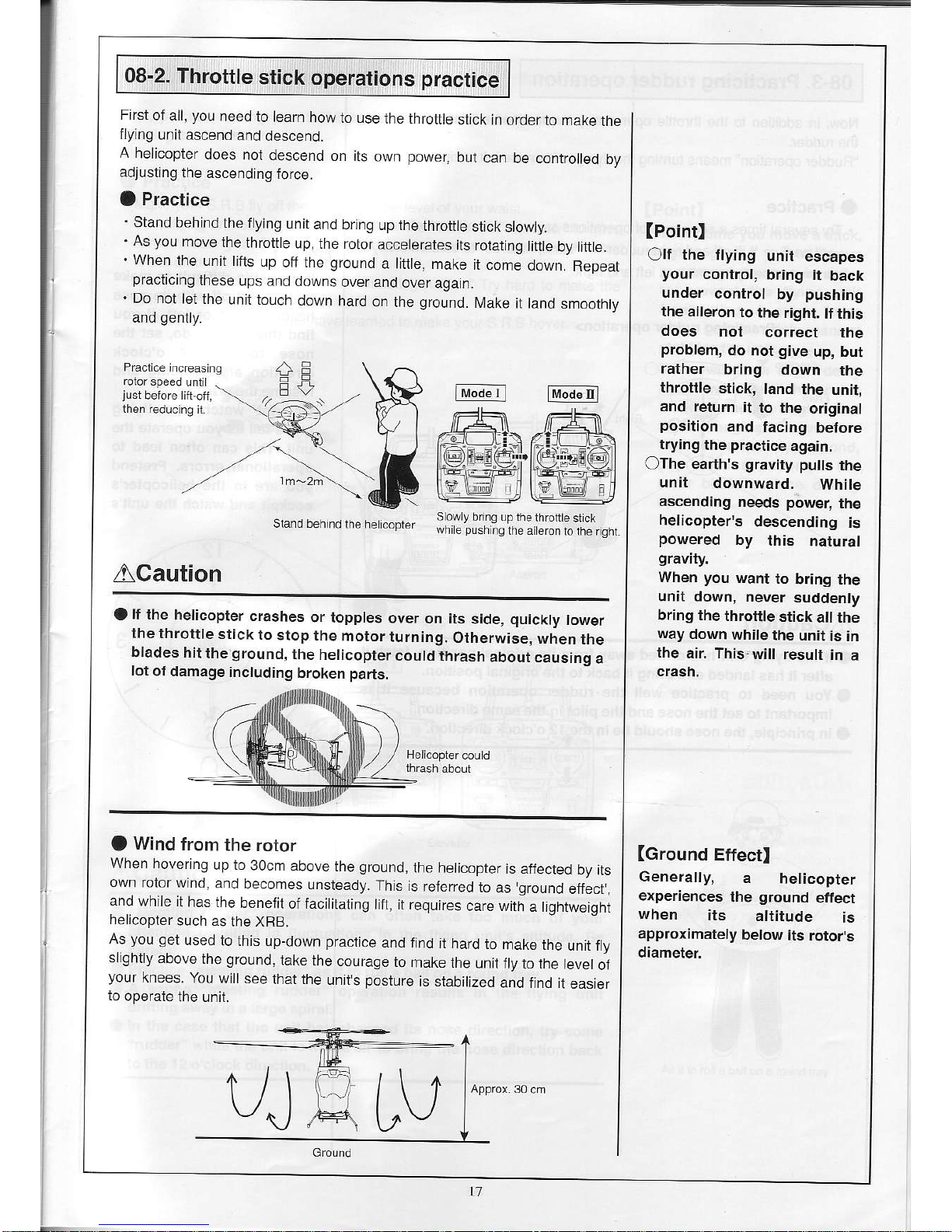
08-2.
Throttle
stick operations practice
First
oi all,
you
need to
learn how
to use
the ihrotfle
strck in order
to make
the
flyrng
unit
ascend
and descend.
A
helicopter
does
not descend
on its
own
power,
but can
be controlled
by
adjusting the
ascerding
force.
O
Practice
.
Stand behind
the flying
unit
and bring
up the
throtUe
stjck
slowly.
.
As
you
move
the
throttle
up, ihe rotor
accelerates
its
roiating
litfle
by litile.
.
When the
unit llfts
up
olf the
ground
a ltfle, make
it come
down.
Repeat
practicing
these
ups and
downs
over and
over
agaif.
.
Do not
let lhe
unit touch
down hard
on
the
ground.
Make
it land
smoothly
and
genlly.
Stand behind
lhe helcopler
sowy
bring up thethrolle
sl ck
whie
push
nq the aieron
to the rghl
ACaution
O
lf
the helicopter
crashes
or topples
over
on its
side,
quickly
lower
lhe throltle
stick
to
stop the
motor
iurning.
Otherwise,
when
the
blacles
hit
the
ground,
the
helicopter
could thrash
about causino
a
lot
of damage
including
broken
pans.
a
Wind
trom
the
rotor
When hoverrng
up to
3ocrn above
the
ground,
ihe helicopter
is affected
bv its
own
rotot w
no. and
beconec
Lnsready.
Th,s
is
refp-ed
ro as
qroJnd
eflecr.
a_d
,/vh
le
'
has
i-e
benetil
ol
f:ciitdrirg
rirt.
r reouirps
carp wit;
a Lgh-we,ght
helicopter
such as
the XRB.
As
you get
used to
this up-down practice
and find
it hard
io
make the
unii fly
slighUy
above
ihe
ground,
take the
courage
to
make ihe
unjt
jlv
to the
level of
Vour
knees.
You wll
see
thatthe
untrs
oosture
is
"tabitzed
a;d.ird
Lea..e,
to
operate the
unit.
l-Cd.'l
lrodetrl
(PointI
Olf
the
flying
unit
escapes
Your
control,
bring it
back
under
control
by
pushing
the aileron
to
the right.
tf this
does
not
correct
the
problem,
do not
give
up, bul
rather
bring
down
the
throltle
stickr
land
the unit!
and return
it
to the
odginal
position
and
facing
before
tfying
the
practice
again.
OThe earth's
gravity
pufls
the
unit
downward.
While
ascending
neecls
power,
the
helicopter's
descending
is
powered
by
this
natural
gravity.
When
you
want
to
bring the
unit down,
never
suddenly
bring the
throttle
stick
a the
way
down
while
the unit
is in
the
air. This-will
result
in
a
crasn.
(Ground
Effectl
Generally,
a
helicopter
experiences
the
ground
effect
when
its
altitude
is
approximately
below
its rotor's
diameter
t1

08-3.
Practicing
rudder
operalion
Now,
in addilion
lo
the lhrottle
operation
you
practiced
earlier,
lry operating
lhe rudder.
"Rudder operation"
means
turning
the flying
unit's
nose
left or right
O
Practice
.
Try several
times
a sequence
of operations
such as
"Lifl
off
and eft
ruddel'
+
"Land"
+
"Lift
oif
and right
ruddel'
+
"Land," in order
to
coniirm
that
you
can make
lhe
ilying unit
turn
left and right
(Pointl
c)lt
is a
little difiicult
to make
the unit
lift off
with
its nose
heading
right
or left.
lf
You
find
this hard
to do,
set the
nose
to
the
12 o'clock
direction
after
landing
and
resume
the
practice.
a)Do
not
watch the
flying
unil's
tail as
You
oPerate
the
Llnit.
This
can often
lead
to
opetational
errors.
Pretend
you
are
in lhe
helicopter's
cockpil
and watch
the
unit's
nose.
<Practicing
rudder oPeration>
ACaution
a
lf the
ilying unit
has drifted
away
from
its original
posilion, fetch
it
afler it
has landed
and
bring
it back
to the original
position'
aYou
need
to
practice well
the rudder
operaiion
because
it is
imDortanl
to sel
lhe nose
and ihe
pilot
in the same
direction'
a
In
principle,
the
nose should
be
in the
12 o'clock direction'
18

08-4.
Practicing
hovering
First,
practice
making
your
S.R.B hover
just
above the heliport without
allowing it lo move oui.
a
Practice
.
Ivake
your
S. R.B f y ofi the he iport to the level
oi
your
waist.
.
If the flying unit begins to driil, use eilher the
"aileron"
or
"eLevatol'to
have
some
"meeling
rudder," wh ch is to move the
unit
in the
opposite direcUon
to the dritting.
.
Every time a drift
begins, use
the
"meeting rudder." Try hard to make lhe
unit hover
above
the
same
position.
.
When
you
master th
s,
you
have learned
lo make
your
S.R.B hover.
(Pointl
OEvery
time
you
move a stick,
try to
give
it the minimum
movement
you
can in order
to
prevent
the flying unit
from tilting. A
quick,
large
move of a
stick cannot
stabilize the unit.
C)There
will
be a slight delay
between when
the rotor
blade surface is
angled ancl
the unit begins to move.
In order to
quickly
respond,
pay
close attention to the
rotor blade surface
during
operation.
ACaution
O
"Meeting rudder" operations
can often take too much of
your
attenlion resulting in fluctuations in
the flying unit's altitude. Be
careful.
(,
Practice
"meeting
rudder"
as
if
io roll a ball on a round tray.
OA
wrong
"meeting
rudder"
operation results in the flying
unit
drifting away in a large spiral.
a
In the case that the
unit has changed its nose direction,
try some
"rudder"
while the unit is in the
air to bring the nose direction
back
to the 12 o'clock
direction.
Mod. r
I lild.nl
As ifto rola
bal on a
'ound
lray
l9

Practicing horizontal movemenl
Practice making
your
S.B.B move in the directon of
your
choice by doing
"meeting
rudder." This is aclually an exiension of hovering.
O
Practice
,
Firsi, make the flying unit hovef at
your
waisl level.
.
Keep the unii's nose in lhe 12 o'clock direction and try movng the unil in
directions of
your
choice.
'Practice
so that
you
can
make the
unit
hover
at any
positjon
wiihin the
flight area.
.
lf
you
can, bring the unil back to its original
position
and
make lt land
genlly.
(Point)
OEvery
lime
you
move a stick,
try
to
give
il the minimum
movement
you
can,
in
order
to
prevent
the flying unit
Irom tilting too much.
Without tilting the unit,
you
tilt
the
stick a
little
and
wait
Ior a while, and the flying
unit
slowly
begins to move.
OTry
to bring the flying unit's
direction back to horizontal
every time it tilts.
ACaution
a
"Meeting
rudder" operations can often take
too much of
your
attention resulting ;n fluctualions in the tlying unit's
altitude. Be
careful.
O
Practice
"meeting
ruclder" as it to
roll
a ball on a
round lray.
aA
wrong
"meeting
rudder"
operation
results in the flying unit
drifting away
in a large spiral.
a
In the case that
lhe unil has changed its nose direction, try some
"rudder"
while
the unit
is in the
air
to brinq ihe nose direction back
to the 12 o'clock direclion.
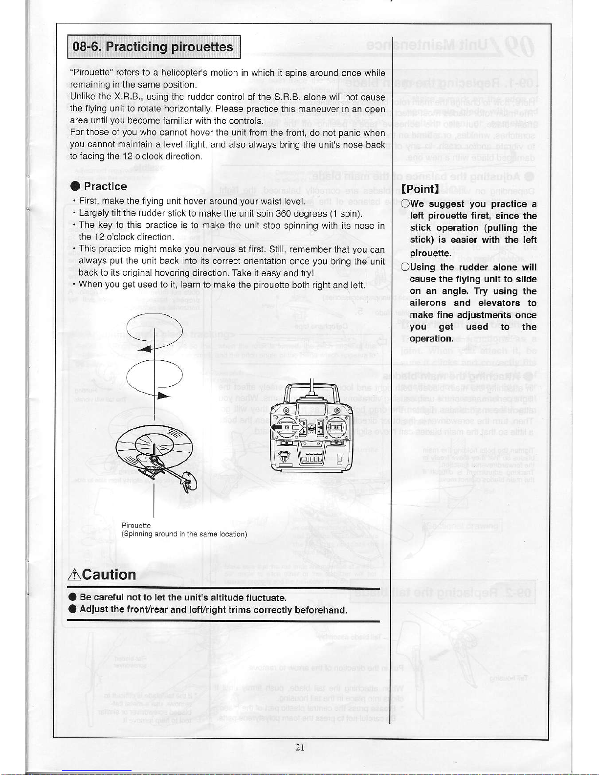
08-6. Practicing
pirouettes
"Pirouetie"
reiers lo a helicopters
motion in which
jt
sp
ns
around once while
remaining in the
same
position.
Unlike
the X.R.B.,
us ng ihe rudder
contro of the S.R.B. alone will not cause
lhe flylng
un;t to rolate horzontaly. Please
practice
this maneuver in
an open
area unt I
you
become famiiar with the
controls.
For those
of
you
who
cannot hover the unil from
the front, do not
panic
when
you
cannoi mainlain
a level ilght, and
also always bring the unit's nose
back
to facing
the 12 o'clock direciion
O
Practice
.
First,
make ihe fy ng unii hover
around
your
waist
evel.
.
Lafgely iilt the rudder
st ck to make the unit spin
360 degrees
(1
spjn).
.
The key to ihis
pract
ce
is
to make lhe un t
siop spinning wilh its nose in
the 12 o'clock direciion.
.
Th
s
practjce
might rnake
you
nervous at first.
Stil,
remernber
that
you
can
always
put
the unit back into iis
coTrect or entation
once
you
bring the unit
back to iis original hovering
direction. Take it easy and tryl
.
When
you get
used to ii, learn to make
the p rouette both righi
and
left.
(PointI
OWe
suggest
you practice
a
lefl
pirouette
firsi,
since the
stick operalion
(pulling
the
stick)
is
easier with the left
pirouette.
Ousing
the rudder alone will
cause the tlying unil to slide
on
an angle. Try using the
ailerons
and elevators to
make fine
adiuslments once
you
get
used to the
operation.
(Splnn
fg around n the
ACaution
O
Be caretul not
to let the unit's
altitude fluctuate.
a
Adiust the tronyrear
and lefyrighl
trims correctly
betorehanal.
rL
q__l
"@"
,
el(-
i"--+:8fl
Y\Es!s!//
ql
2.1

/lO,/'' unit Maintenance
09-1. Replacing
the main blade
Here, how to change
ihe maln roloT blades
is exp a ned.
The main
rotor blades rnost aflect
the ilying
periormance.
Not only a broken
main blade,
bul also the adheslve
tape's
peeing
oif
lhe leading edge,
scraiches,
wrinkles, or a bend
on the main blade can
all cause lhe
fy ng unil
to vibrale
and/or crash.
In
any
oi the above cases,
be sure to
rep
ace
the
damaged blade
with a new one.
a
Adiusting the balance
ot the main blade
Depending
on wheiher the
man blades are colrectly
balanced, the
flght
quality
diilers
drasticaly. Adjust
the balance ol the
main blades using
the
orovided blade
balancer.
1.
4.
Applycellophane
lape elctolhe
lghler blade
u.l eit and rlght blades
afe baanced.
5.
a
Attaching
ihe main blades
In atiachlng
lhe main bLades, both
tight and loose screws
adversely affect
th-o
flighl
performance
ol the unit, causing
vibratons and other
problems
When
you
attach
the majn blades,
lighten the drag bo ts once
as much as
they w ll
go.
Then, turn
the screwdrlver
ln the oiher d reclion
by one lurn to
loosen the bo ts
a liit e so
that the ma n blades
can rnove slighily backward
and
forward
Tighren the bolls
hod ng the ma
n
blades so rhal lhey
move Jreey rn
the ioMardneverse
direct on
Trackinq adjustment
is diiicLl f
the nain blades
cannot move
09-2. Replacing
the
tail blade
P!l!
n the direclion otlhe
arrow to remove.
When atiach ng
the lai blade,
push
lirmly unti
clicks lnlo
place
in the iai holsing
'
Preas"
pres,lle
F-rra
p.,.Lpdro+15"bldde
Ba.d e,Llno_
_o
p'ac:
lhe oa"
ooyr\'ene
pa-s.
B ade ba ancer
(ac.essoresl
(Pointl
aAdiusting
the balance
of the
blades dramatically
improves
the hovering
stability ol the
unit.
Olf
the blades are seriously
oul of
balance, change lheir
combination and
try to apply
the least amount
of adhesive
tape
possible.
ls thetail
vibrating
(hunting)?
f the tailvibrares sd€
lo sde or sways
slghly
lrom side 10 sde, t s
possbe
the 1ai blades are our oJ
balance. To
check baance.
pass
the ncluded 69
mm a en Mench throLgh
lhe 1ai blade
ce.lef mounl ng
hoe and notice I one
sde
goes
up or dow. lf the tai biade
moves. add a sma
lp
ece
ol lape to lhe
hgh side
(lighrer s de) lntiL the tai bade
does
nol frove when checked
aqa n. A
propery
balanced
rail bade wll ay
horizontalas
pclured
be ow
The
un r sways sLigfty nom sdeio
sde
I on€
sde or the bLade drops ower|ran
rhe other,llre b ade s
iot baan.ed.
'
rl1he ralbade is d filc! t
to
remove,
Lse a mela lat
bladed scfewdr ver or
s miar
loolto
help remove il
22

09-3. Tracking adiustment
O
Adiusting the Tracking
When lurning the nrain blades, adllsr so that rhey both irace the sarne
palh
and
appear
to overlap This s reJerred 10 as trackng adjustmenl . Vlbralon
wiloccur,
having a negaiive effeci on I
ghi,
if the b ades do not track correcty.
For the
SRB
lracklng does noi need io be
perfect
A 3mm or ess
gap
beh4/een the ivo blades s
acceplab e. but
lor
a smoother
Jly ng lre t s worth the tme io
get
the lracking as
close
as
poss
ble. Also check lor
play
n the b ade ho der and remove by iwisling the
b ade
grip
downwards as
pictLrred
lhen check and adjlst the lracking with the upper
pltch
rod accordingly.
Adjusrnenr require.i f rr ades
appear ke lh s when roiaiin9lhe
L,,.,"",",
,.,",",.,.,.
;l
shorren ro eriiolenqthen
(J
Delemlno whclhcrth€ marked b ade
Agapor3 nn.f ess betrreeo
<Adjusting main blade tracking>
(-Lo"s",
a
{shorrer
,.Badelroid€r
.j(
"€<:
"
'r
-:ffir
,i
Adjusl the
length
of
ihe
ptch
rod so that whe. lhe rotor s lurned the
ptch
afge ol the
bade
which appears lo be above s smal. and the
pltch
ange oflhe blade whch appears
to
uark re man b ade w rose
prch
How to
adjdstlherracking
lurn nN anjLEtinE
fod
io
ir.
ttrrn rtir rdlu{idg roJ brli.
Wh.r !r.knr! rd unDeDrs.
turn rhe xdlu$ing
'o,i r lf
or one
re\oluti.r rt r tirrr
rnd lnrl rh.lo.arian{hcrc
rhe irr.kin!
rn I
rrhe\
tbc
(Pointl
OMake
a mark on the edge of
one main blade w;th a red
felt-tip
pen
or something
similar
ACaution
OThe
exterior of
the main
motor
will rotale when
you
turn the
main
blades.
Be
careful
not to touch the
exterior of the main motot.
(Note
about the rod end)
The rod end functions as a
ioint.
When
you
attach it, be
sure it clicks and correctly lits
to the ball. lf it is oul of
posilion
or
pressed
too far
inside, the
rod
end cannot
lunction
correctly
resulting in
a crash.
Sectiona drawing
23

09-4.
Aileron
and elevator
trim adiustment
O
Adjusi
the lrim
if the flying
unit moves
iorward/reverse
or
lelt/right
without
operation
ol the stick.
Adjust the
trim by using
lhe trim
lever or the
transmitler'
'.dl'
r>ef
<Fixi
ng f orward/reverse
movement>
.
lf lhe
flying unit makes
an unwanted
move
iorward,
move the
elevator
trim lever down.
(The
black
arrow
jn
the drawing)
.
lf the
flying unit
makes an unwanted
move
backward,
move
the elevator
trim lever
up.
(The white arrow
in
lhe drawing)
<Fixing
lelvright movement>
.
lf the
ilying unit
makes an unwanled
move
to the
right,
move the
aileron trim
lever left.
(The
black
arrow
in lhe drawing)
,
lf
the ilying unit
makes an
unwanted
move to the
left, move the
aileron trim
lever
right.
(The
white
arrow
in the drawing)
+
tr,r"d" t I
+
FmTtEl)
24

@
Does the unit
proceed
straight?
ll the he i f ies s deways when foMard
input s made,
or
if the
hei flies foMards
or backwards when aileron
or elevator
is
lnput when hover n9,
please
check the orientation
of the main
shalt componenls
as
piclured
below
lf
the washout cenier hub
and
mixing
arms are nol
perp
ndicular
to lhe siabiizer blade
as show
in
the diagram, oosen
screws C
and/or D, realtach
screws C and/or D and check
orrentalion ol
these
paris
again. Adjust
unil ihe two assemblies
are
perpindicu
ar to
each other.
li the screws are
overtightened n the holes on the main
shaft, the
orienlation angles may
become misa igfed. Do not
overtighten.
Stabr zer blade
Cenler hub
How to
adiust and check
1. A ign lhe A and B balls
on
the
same axis.
2.
l\,4ake sure that lhe stab zer ll
ade is
perpendicular
to the wash control
arn
and the swash
plaie.
3. li they are not
perpendic!lar,
loosen
screws C and D to adjust ihe
angle and
then re{lghten
them.
ea.z.--2?..-,4r
E
r4
_15

09-5.
Rudder
trim adjustment
If the flying unii turns to either lhe leit or righi while hoverlng,
you
need to
adiust the rudder lrim.
Do not
adjust
the rudder trim
by using the trim lever on lhe transm tter. Leave
the rudder lrim
on
the transmitter in
the cenlral
(neutral) posilion.
Turn the
rudder neutral adjustment volume
on
the
control unit to adjust the trim.
IPointl
RUD NT BLdder neulral adjustmert volume
Leave the rudderlrim in
the
neutal
positon
and do not move it.
(lf
the rudder
deviates
from neutral after
several
minutes
of flightll
The ruddef
is equipped wiih a
gyro,
and when lhis
gyro
element
heats
up, it will deviate from the
neutralposition.
In
such cases, turn oif lhe
power
and then turn it back on agajn.
The unit wilL
again
try to tind
the
neutralposiiion.
z-\
rf
l
\\,/
ll the flying unit turns to the left,
adjust the volume to the right.
B
/<tt'
To turn
the
swrch. be sure ro use
A:
the lal bade
plastic
screwdrver
conlained in
your
sel.
l([@)EaHFdt
lf the flying
unit
turns
to the I
adjust the volume to the left.
26

09-6. Adiusting the rotation speed of the
main
blade
This
seclion
descr bes how io adjust the rotation speed of the main blade by
adjusung
the main blade
pitch.
With the
S.R.B.,
you
can check the rotalion speed of the rnain blade while
hovering
by
looking
at
the LED display.
Confirm thai the approprlate rotation speed has been reached before
adjusUng.
The rotation speed of the S.R.B. s
main
blade
while hovering is
around
1,800
to 1,900 rpm. The LED
w ll
lurn
red
once the speed
is within
this
range.
IProcedures]
O
Turn
on
the
power
oi
the transmitter.
@
Place
the Lrnit on a
flat
surface, and
turn
on
the
power
switch. Do not move
the
unit
unti the flashlng
green
LED turns to a solid
green.
O
Press the
slart switch
(with
the transmitter throttle stick at the lowest
posilion).
Ho d the un t in
your
hand and
gently
increase the throtlle speed
uniil hovering speed is feached and a rotation speed, where the unil is
just
ab e io ift iiself, is reached.
When the rotation speed is righli
hl up. - This indicates the right rotation speed has
been reached, and
there is no
problem.
Check the rciation speed with
li lhe red LED does not come on even though the hovering speed
has
been
reached, slop the unit and adjust
the
pitch
angle adjustment screws
of the
lwo
main
blades by turning each of
them
by
the
same
number of rotations.
n
: .-
Fed LED tLrns ofl
d
n"o reo ignt" rp
a
LED lLrns ofi
When the rotation speed is too high:
s on ard lhen oft before
hovering
speed
is reached, it
)tation
speed
is too high.
adjust the
pitch
angle by
turning ihe
pitch
angle
'ew
to the right to reduce the rota:ion speed.
When the rotation speed is too
low:
rnot
flash ot turn on even once,
the rotaiion speed is
adiust the
pitch
angle by turning
the
pitch
angle
:w to the left to increase the
rolation
sDeed.
This
part
wiL move when
(Pointl
OBe
sure
to turn equally both
of the two
pitch
angle
adjustment screws.
Use
the Philips screwdriver.
ACaution
aDo
not turn the
pitch
angle
adjustment screws too
tight. lf
you
do,
you
can damage their
threads. Moreovei
please
note
that they are fixed
with
a
special
kind
of
nut known
as a
Iock nut
so
that they cannot be
disassembled.
alf
the
pitch
angte adiustment
screws of the two
main
blades
are turned by diflerenl
amounts of
rotations, the
tracking will be out of
position.
lf
you
are unsure of the
trackino. check this area to see
at about
the
same angle, and readiust them
until bolh
appear
to be at the
same angte.
The red LED will lig
lf ihe red LED turns ol
indicaies that lhe
rotati
--tln
such cases, ad
adjustment screw
li the red LED does n(
-+ln
such cases, ad
adjustment screw
Pilch angle adjLstnent
screw

l/l .,rt"Usinq
a Commercial
Transmitter
When this
producl
has not been
purchased
as
the iull set, which also
includes ihe
transmitter, it is
possible
to use a commerclal
transmitter
made
by Futaba
Corporalion. Sanwa
Electronic Instrument
or Japan
Remote
Control Co.
Ltd.,
(JR).
lf
you
have
purchased
the set wllhout
the
programmabie
transmitter,
you
can
purchase
a
transmitter made
by any ol
the above
companies.
*
You can also use
the transmilter
that comes with lhe X.R.B.
complete set
ACaution
O
Transmitters
that can be
used
lvlanufaclurer:
Futaba Corporation, Sanwa
Electronic
Instrument,
or Japan Remote Control
co. Ltd.,
(JR)
Ivodulation
syslem: Fl\,4-PPM
(you
cannot use Al,4 or
PCNI.)
Channels:
At least 4 channels
.
I\losl transmitters
now on sale are
compulerized transmitters,
and even
if not alL
their functions are used,
generally
it
will
be
possible
to
fy lhe
unit
wiih lhem.
'
Either reset the transmit(er
data befole use, or
use a model
that had not
had data input
into it
yet.
.
When
initializing lhe unit,
having ihe data a ready
inpui nlo the
transmitter
will
prevent
initializatlon
trom being
performed
correctly, and
there
is a chance that the unit
will not operate.
.
Transmilters otheT than
computerized llansmllters,
incuding airplane
transmitters, can also
be used to lly ihe unit.
<l
OAMays
set thetrim controls
in the cenler
position.
QAlways
set ttre
modulation to PPM.
(You
cannot use PCM.)
(OAlways
select
normal type
if
using
a swash
plate
type.
(You
cannot use swash
mode, CCP
mixing or CCPM.)
Futaba:
HELI SWHl
Sanwa:
NOR
JR:
lSERVO
ONever
use
revolution mixing
(tail
curve).
1.
Selecting
the
manufacturer selting
Turn ihe
power
switch on
the unit side off, and
the 0.89 allen
wrench included with the
unit)
use a thin-end
rod
(such
as
to change the
control unil
OFF
ON
OFF
ON
tG]
EI
[a],.11
OFF
ON
FUTABA
{'a
lCn
2ch
3ch
4ch
Futaba
(nitialselting)
AIL ELE THLRUD
Sanwa ELE
AIL THL RUD
JR
THL AIL ELEBUD
Channel setting
for each
transmitter
manuf acturer
(Pointl
The transmitter
selection
switches
are numbers
1 and 2.
Note
that both 1 and
2
switches
must be
in the
correct combination.

i
Turn
on the lransmitter
oower switch.
Resei the
data or select a model that
does
not
have data entered. Some
manuiacturers
use revolution mixing
(ta
I
clrve) in the initial setting so it is
important to disable this function
or set all va ues to 0%.
Turn
on the llying unit
power
switch.
Checking
the direction of servo
operation
Check to ensure that
operat ng lhe transrnitter
stjcks
moves
the servos as
shown in the diagram
be ow.
lf the allocation
or
movement
direction oi lhe
servo differs
from
the
diagram, reset the
setting as shown in the table
of "Channel setting ior
each transmitter
manuJactured'in lhe
previous page,
according to the
transmitter's instruciion manual.
(Pointl
Please do
position
of
hole.
not
change the
the
servo horn
lild.nl
5. Adjusting the servo neutral
posilion
When
the aileron and elevator strcks
of
the
transmitter are in the neulral
posiiion,
ad usl the transmitter irims so that the
aileron and elevator servos
are in the
oositions as shown below.
In lhe case thai a computer
transmitler is used, use the sub tdm iunclion.
_.----l
tl,rode I I
t+kd;:qf
29

6. Throttle adiustment
When using
a commercially available transmiiier, since the ihrottle rudder
angle difiers depending on iransmitters, it musl be adjusted by following ihe
Procedures
outlined below.
IP.ocedures]
O
Turn the transmiiter
power
on.
@
Place the unit
on a
flat
surface, and turn on the
power
switch- Do not move
the
unit untillhe flashing
green
LED lurns lo
a solid
green.
@
Set the transmitter throttle
stick to the slowest seiting.
Adjust the lhrotlle
stick by turning ihe THR ATT
(lhrotUe)
adjustmeni
volume
untilthe red LED lights up.
(Pointl
You
cannot
safety
device
green
ancl red
the same time.
disengage the
until both the
LEDS light up ai
Tl-lR ATT Thrott
e adjlslment
volume
The lhroi e's slowesl
posltio.
s
raised
@
Raise the throtlle
stick, and check that me red
siick
posiiion
at
which
the red LED iurns off is
molor
slans.
@
Wiih the transmitter
throttle stick in the slowest
LED on the conlrol
unii on,
pressing
the start
safety device and allow the rnotor
io stair
LED has
turned otf. The
the
position
at
which
the
position
and with the red
switch wiil
disengage the
7. Budder neutral
adjustment
Please refer to
secton 09-5 on
page
26 for instruclions
on adjusling ihe
rudder irim.
30

I1,,rrill,9.lt.",,n,1mp"it"l"fi
l.o.tF.lilins","f"r"Rp.l
ems
a
The
part
that has
the most mpact
on
helicopter
ilying is the main
blade. There
are often cases when
jlyirg
performance
has been lmproved
j!sl
by replacrng the main
blade. l\,4oreover there
is a big diiference in ilying
performance
between a hellcopter
with a balance,adjusted
main blade and
a main blade that has not had
the
balance
adjusied. In cases when
the helicopter
js
not flying
well, we recommend
the first ine
of action is to
replace
the main blade with
one
that
has had its balance
adiusted.
a
lf
the flying unit does not move
at all
O
Check that the
power
ol the transmitier
and flying unit are
on.
-.........
.....Seepage13.
@
Check lhal lhe baitery eve
s of the batteries in the transmifler
and in the ilying un t
are sufflcienl.
......-.
See
pages
5 to 8
and see
also
the instrucUon
manua iorthe
ttansmitier.
O
Check lhat the radio frequency
ol the transmitter's
cryslal is the
sar.e as that ol the I
ying
unit.
............
See
pages
7 io
g.
@
Make sure that the
crysial has been inseneo
propeny-............-...........
..-...
See
page
9.
O
Check that the transmitter
manufacturer
selection swilch is set
correctly.
....................................
See
page
28.
@ThjsprodLrclhasbeendesgnedsothalwhenlhesaielylockhasnolbee.clearcd,themoiorwllnoirotale......seepagels.
@
ls the
throttle trim raised lo the
up
posiiion? ...-
See
page
14.
@CheckwhetherthetransmittersrnodulaiionmeihodisellherAI\/orPCI\,,1.....seeatsotheinstructonmanual
for
the transmiiter.
a
lf ihere ls laulty
operation or the ilying unit is
moving
jerkily
O
Check that lhe battery levels
ol
the
batteries in the transmitter
and n the flying unit are suffic
en1..-....... See
pages
5 to
8
and see also lhe instruction raanlal
for ihe transmiiter
@
ls the
antenna oi the transmilter
extended?
..
....
See
page
.j4.
@
There is
a
possibility
that radio waves
of the same irequency
are being used nearby.
.......-..........
See
page
3.
@
The flying
unit suddenly lands
during a fljghl
..............................
See
pages
6, 15,49.
@
The LED
amp on the S. R.B.
control unit flashes to indicate
an error, of there is motor
noise
...-.
See
page
43.
@
When
the throttle s raised,
the motor turns but the
unit does not take off.
................-..................
See
Daoe 32.
O
When the flylng unit
does not slop rotating
OThe
rudder has not
been adjusted
property... -.
See
page
26.
@)
lt is
possib
e the tail
motor is damaged
or
worn.
...... .
...
Rotate the tait rotor
by hand to make
sure
it rotates
smoothly
and does not
generate
strange noises. lf
not, replace the motor.
a
When
fyjng ufit moves foMard/reverse
and left/righl,
and cannot hover
O
ls
the llying unit be ng caught in
a wind caused by an a r
cond tioner or ihe like?
-..Continue
praclicing
when ihe
air
is
slil
unt
lyou
are lami arwith ihe contro
s.
Fy the
unit with the windows closed
and the air condiiioner
off.
@
ls
the trim adlusiment
done correctly?
....
See
page
24 to 26.
Olsthegfoundeifectnotaffectingtheflylngunit?................-...-............
....Seepage
j7.
@
Do
you
understand the drift
etfect wth single rotor heiicopters?
.......-.......
See
page
16.
O
Doesthe
u nit fly straig ht?
.
..............
.....Seepage25.
a
When the unit vibrates
strongly
O
ls the tape on the
edge of the main blade coming
off?.....................
....-.
See
page
14.
@
ls main
blade moving
smoothly in forwards/reverse?
.........................
....
See
page
22.
@
ls
the lracking adjustment
done cofiect
y?
...
.....
see
page
23.
@
Are the main
blades' centers of
gravity
balanced correctly?
.......-......
See
page
22.
O
ls the tall blade
balanced correctly?
.........-....
.
See
page
22.
31

12di,"oJp.e."*,gmp,"linp*nn9;ge-".""-g"nlklins,#'-",,tl.y*i,il"9,xni1'','*',",""""',,',,,'',","
12-1 . General
guidelines
on
disassembling
the
flying
unit
Rotor
head
Remove
the swash
base
Plale
rod
end attached
to lhe
swash
plaie
ball, and
loosen
the main
I,42X6CS
to
remove the
enlire
mast.
ano
gear
main
S.R.Bswash
base
plate
Frame motor
s.R.B.
Control
unit
Loosen
the
lhree
[/1.7X8TS
screws,
and
slide upwards
so the
control lnit
can be
removed
llom
Disconnect
the
tail motor
connector
and
loosen
the eight
M1.4X5TS
screws
io
remove the
iail irom
the
matn lrame.
M2X6CS
(oily
needsto
be loosened)
the main
irame.
skid
Loosen
lhe four
M1.4X5TS screws
lo
remove
the skid
from the
main irame.
@a
M1.7X8TS
IV]
4X5TS
ls the main
geal
screw
tight?
lf the
M2x6 cap
screw in
the lower
mast lock attached
to the
lower
black
main
geal
comes
loose,
the main
gear
will slip
on the
main shaft
and the
motor will
nol be able
io drive
the
rnain
roior head
properly
thus not allowing
the
helito
lil't off
when
power
is applied.
Please
check this
screw
from time
to time
as
part
ol
maintenance.
Cap screw
M2X6
Allen
wrench
1.5 mm
(accessones)
To
rtuv.nl
bFaking
orovenighteni|-s
ol the
s.rc$.
place the tip ofthe
knrg'r end ol
$c alerrvenchinrotheh€ad
oflhecrp
\ctuw Llse
ihe shoncr end
as thcrglrtenrnC
lerer
IIlh.lon8ersidc
is lsei 4
thc tiAhtering
l.vcr and
ihe \hodor end
N
Put
rnto
rhccapscre$.you
mat
br€al drc scEN
duc10ovediehtt
ng
32

12-2. Rotor head
ing lhe
posilion
ol the o4 balls in rhesrabirizer
O)
D
sassembling the I nkage
rod, slabilzer,
and main blade
tvl4X4TS 2
M1
4X4TS-2
'
@
Use the hoe on
\\ the oLterside
---_-t1\.
Pllch rod
/
€)
I
e)
Disassernbling the
swash p ate ASSY, wash
out ASSY,
cenler hub
blade holder ASSY.
and seesawASSY
Mi.4X5TS 2
lMl 4x7 3 srepped
screw
S.R.Bcenler hub blade hoderASSY
(Can.ot
b€ disassembled)
[,41.4X3TS
Ml4X5TS
Ml.4XJTS
M1 4X3TS
Appd rmm
Stabilizer conlrol rod
Mixing arm rod
M1 4X5TS
SRBswashpateASSY
l3
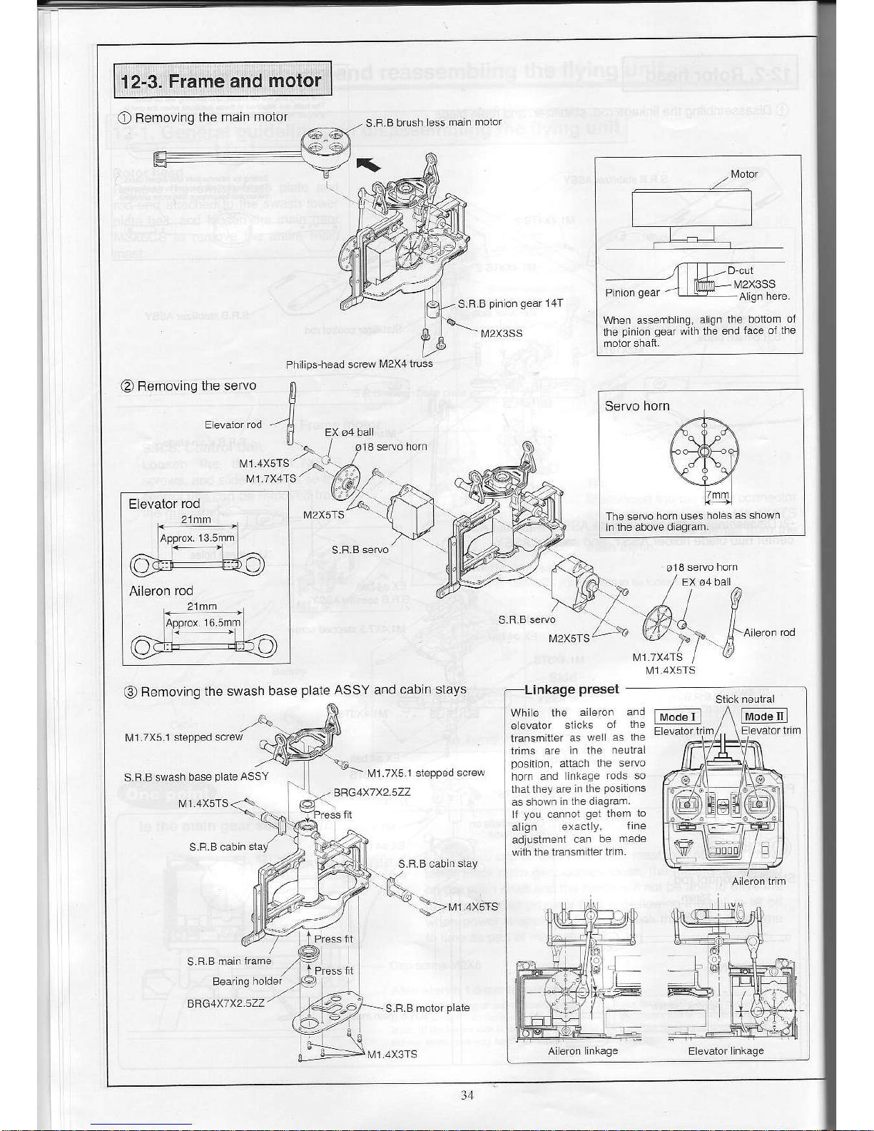
Femoving
the main
12-3.
Frame
and
motor
o
S.B
B brLsh ess
man motor
,/Ma.:l
L
r- T
-
tvl2x3ss
I/t2X3SS
When assembing.
algn
the
pin
on
qear
wth the
@
Removing
the seruo
Philps
head screw
[,l2X41russ
M1.4X5TS
M] 7X4TS
Elevator
rod
Aileron
rod
M2X5TS
[41
7X4TS
@
Removirg
the swash
base
plale
ASSY and
cabin stays
nkage
preset
l!11
7X51 slepped screw
Whie lhe
aieron and
e evaror
slicks
ol lhe
lransmiller
as
we as lne
lrims are
in the neulral
poston.
attach tlre seruo
horn
and linkage
dds so
thatlhey are
n the
Positiors
as shown
n Ihe dagram
I
you
cannol
get
them
lo
align
exact
y.
ll.e
adjlstment
caf be
made
wlh the transmrtter
tr m.
l-M;;ll
lM"denl
S.B
B swash
base
plale
ASSY
M1.7X5
1
BRG4X7X2.5ZZ
M] 4X5TS
M1 4X5TS
M]
4X5TS
Servo
horn
The seruo
lrorn uses
hoes as slrown
N41 4X3TS

BRGz.5X5X2.3ZZ
'{-$.
S.R.B tailLnit L
M1
4X5TS
Mt.4X5TS
S.R.Blaillin
S.B B tailboom
holder F
Aliqn ihe
convex
pan
oi the iaillin
with
lhls hoe and lil il
in.
ign lhe
convex
parl
oj the lai
boom ho der
wilh
thrs hole and it t In.
Aftach
so
that
the cord is
to lhe rightollhe ilying
unit.
JV1 4X5TS
S F.B core less tailmoior
S.F.B talldrive
shail ASSY
Insen
inlo ihe tai motorcoupting.
S.F-B tailboom
holder L
35
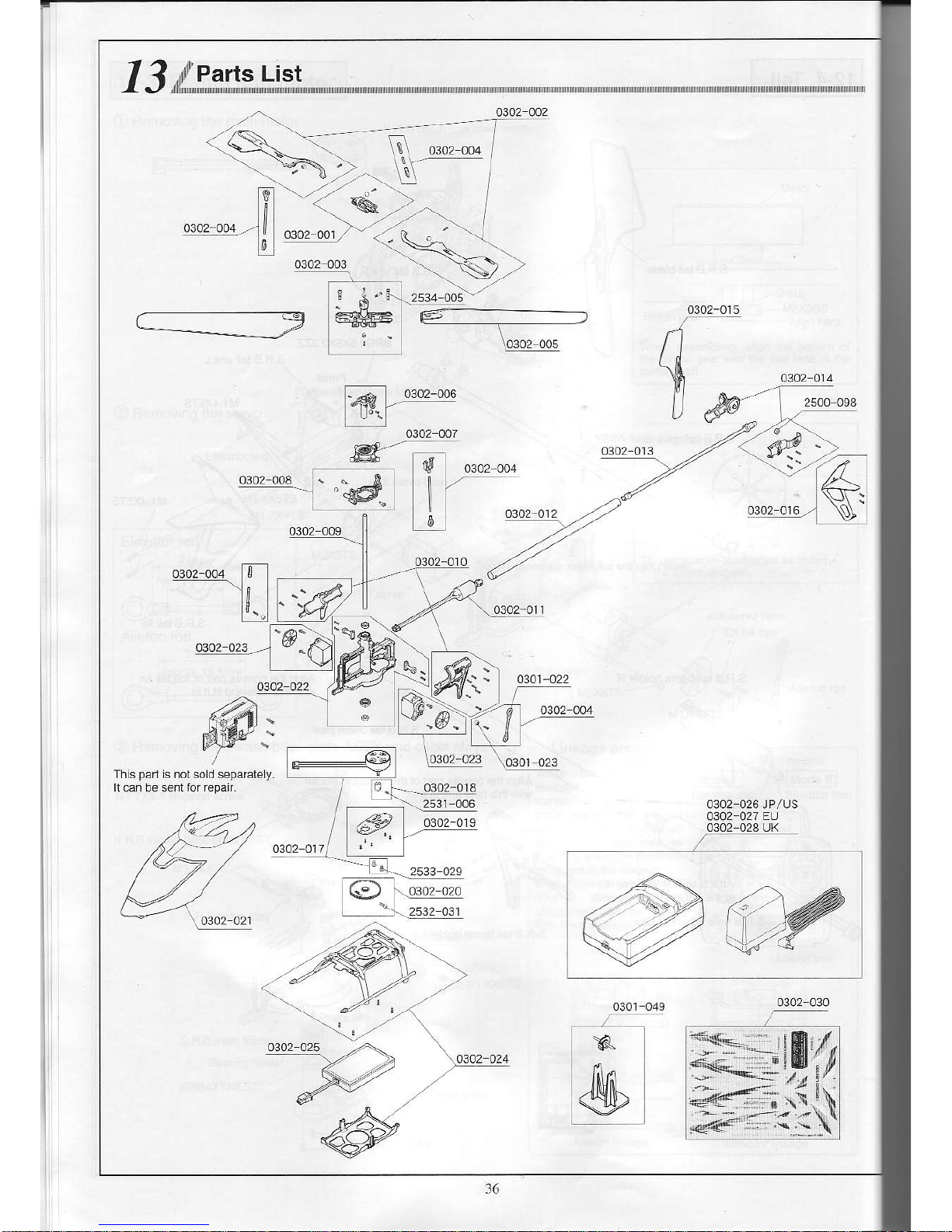
13,d,,F""nII;,,
List
tfl
o:oz ooa
,-]l]
0302-006
0302 007
0302-015
n
\h
U@
4302
014
Kl_-
u..,
d
fs l o.or-ooo
[|-
-
o.roz oor
ltr I
tl
Ths
part
s nolsold separalely.
h can be sentlor repair.
0302-026 JPlUS
4302 027
En
0302 028 UK
R-
@
0302 030

Code No
o3o1-o54
xFB
SR crysrar
[72
51oMHJ36]
o3or
oss
xFB sR
crysrar
i72
55oMNz/3aJ
xBB
sR crysra
172
seoMHzt4a)
172.&aMH/4z)
xFB
SR crysrar
t40
665MHz/501
xRB
SR crysrar
I40
5e5MHz/s3l
iI9
"lj11:
r.10
715MH2/541
t4o.735MHzls61
xFB
SR crystar
t35
o4oMHz/641
xFB-sR c.ysiar
135.o3oM
H2l63J
xBB
SR crysra
135
12oMHzn2)
s.R Biar'rrv6
shafr AssY
0302
014 s F B rarunrt ass
r
s R B
bursh less mar moler
o3ort1, S,c€ -".,
phl*
0102.026 7 4V 2.e/Lpo
bafre
y.h.raerJpius
o3o2
027
7
.,1V
2cerr L
po
baftery charser EU
o3a2 a2a 7 4\/
2cet Lrpo bafrerychaeer
UK
sRBOuarkscrcwset
ser scfew M2x3
(uni,.hrdme)
Ph lips
hea.r s.rew M2X4trlss
Tappins screw M2x10
Type 2 groov€d
1.o5o
tiI
I
L
(!s!L
]t
60q
(1
600)
I
ti1
ji:t
l
L2ool
qp!sl
soe!)
9goo)
9pqa
Leco)
GgE
GSq)
GqSL
11!9L
,o
;
one
compeie s.rew
and
pn
sei
(ror
i Lnr)
'The
prices
in
parertheses
are the
pricesexc
uding
consumpton tax
'As
pad
of our commitmentro
ensur ng
maximum
safety, rhe main
btades and rait
btades are made
oi foamed
potystyrene.
You should
considerthem
as consumabte
items.
ptease
careiu[y
check the code numbers
in the
aoove nsr.
31

14-1. Changing the aileron and elevator rudder angles
.
The rudder angle is set to the low seiting when the llying unii s shipped
from the faciory
A selector switch on the control unit can be used to switch ihe aileron and
elevalor rudder angle to a two-step selling.
Normally, the rudder angle s set to the low
selling.
Please leave it on this
setiing !ntil
you get
used
to the
controls.
Switching
the
angle to the higher selling makes the steering more
sens
tive. Whlle this
allows
more
precise
operation,
it
also
makes
control
more
difficult. Use
this
setting
when
greater
rudder
control
is required,
such as
when flying
the unil outdoors.
IProcedures]
OUse
a
thin-end rod
(such
as the 0.89 allen wrench included with the
unit) to change the
control unit switch
(see
the diagram below).
OFF ON
z
\
1'l'l:"-:ll:l!::'ry: :-l:: @
On
(rghl)
-
rudder angle al high selting
Otf
(let)
-
rudder angle al low sefiing
Norma ly, use lhe llying
uit
with
the sw tch set io Oll

14-2.
Adiusting
the throtfle
curve
'
This
setting is
adjusted when the
llying unit is
shipped from the
factory.
This section
explains how to
adjusi the transmitier,s
throtUe
stick to
the
ceniral
(neutral) position
when hovering
by adjusting
the conirol unii,s THR
CRV
(lhroltle
curve) adjustment
voJume.
(Pointl
THF
CFV Throtl
e curye adlustmenl vo
ume
When
the lransmiiteas
throttte
slick
posrtion
when
hovering
is below
the neutral
position:
Turn
the THR CBV
(throttle
curve)
adjustmeni
volume
to the left.
The thron
e stick is near
the ne!lralposilion.
The transmitter's
throtlle
stick
should be in the
central
(neutra
)
Position
when
the unit is
hovering.
(What
is
the throttle
curve?I
As
shown in the lollowing
d agram, the
throttle
curve
means
the
adjustment oi the
motor
output in
relation lo the
stick
posilion.
Z1
rf
l
\v
50%
t
When the
transm tter's
throltle strck
posilion
when
hoveing is
above the neutral
position:
Turn the THR
CRV
(throtue
curve) adjustment
volume
io the right.
Throttle
stck s above the neLtra
posirion.
;-sJ!-,\=q:
l@)EeHfE)
tt,todeul
.,..-:'/.\r
f+)-EsEr@)
ln.d"rl
I
r\i.de
r
I
llrod"E
39

'
This
setting is adjusted
when the flying
unit is shipped from
the factory
It
is
possible
lo
use the control unit,s
RUD ATT
(rudder
rate adjustment
dial)
to speed
up orslow down
the rudder rotation
speed.
(PoinrI
Ii is
possible
to adjust the
speed
at which the flying
unit
rctates
during
pirouettes.
O
O
Tum to lhe right
to increase
y' ihe roranon
speed.
|
(-\
\57
'
Turn lo lhe left to de.ease
the rolalion speed

14-4. Adiusting
the
gyro
sensilivily
'
The
gyro
is adjusted to the righi sensiUvlty level when
the flying unit is
sh
pped
lrom the factory.
By
switching
to the
gyro
sensiiivity adjustmeni mode, il is
possible
to adjust
the sensitvlty
of
ihe rudder
gyro.
When the sensitivly oi the
gyro
is
high, lhe ta I will vibrate slighty
back and
forth. a
phenomenon
known
as "hunting".
On
the
other
hand, when
the sensitiviiy is low, the tail hovering will
be
du led.
IProcedures]
O
Tufn the transmitier
power
on.
@
Place the unit on a flat
surface, and
press
the
power
switch- Do not
move the unii uniil the ilashing
green
LED
turns to a conslant
green.
@
Press the start swiich
(with
lhe transmltter's
throttle stck at the lowesi
setting).
@
After
disengaging the safety device, again
press
the start switch while
keeping the
throttle stick oi ihe transmitler
al
the
slowest
position.
OThe
tone
of the
motor
will rise, and the red LED will
begin to flash,
indicating the
unil
is
now in the
gyro
sensitvty
adjustment
mode.
@
Once in the
gyro
sensilivity
adjustment mode, the RUD ATt
adjustment
volume becomes the
gyro
sensitivity adjuslment volume. Fly the
unit,
and adjusi the sensitivity until il is
just
short of causing ihe tail to
start
"hunling".
OAlter
adjusting the vollme,
it is necessary to save the
gyro
seltings- Hold
down
the
slart swlch, and
press
the
power
three seconds to turn off the
power.
@The
next time
you
lurn the
power
on, the adjustment function of the RUD
ATT
adjustment volume reverts to
jts
normal function,
so either feturn the
RUD ATT
adjustment volume to its origjnal
posllion
or carry out the
adjustmenl again.
The
FUD ATT rudder rate adjustmert valume
becomes the
gyro
sensitivily adluslmenl vo
ume
sensrvrly
swllch
for
Tu.n to lhe rioht to ncre4e
the ovro sens tNilv.
F r^'.,
t(
rt
w--/
Turn to
the bn lo decrease the
gyro
sensilivily.
When the
gyro
sensiUvily is high,
Hunllrg
When
the
gyro
sens tivity is low,
)
therai hoverng wjl be du led
lPointl
After
completing the
gyro
sensitivity adiustment mode,
the RUD ATT volume
position
will
be reflected on the rudder
rotation
speed.
Please readjust lhis volume
to
the desired setting.
4I

14-5. Adiusting the sub-trims
-
This sefiing is adjusted when the flying unit is shipped trom the factory
Wiih the transmitter
aileron and elevator sticks
jn
the neutral
position,
the
aileron and elevator servos can be adjusted as explained
in
ihe
following
procedures,
by
adjusting
the
aileron sub
trim
and elevator sub
trim.
IProceduresl
Turn olf ihe
power
of the transmitter and llying unii.
O
Turn the transmilter
powef
on,
@
Hold down the stan switch and
press
the
power
switch- When the red LED
starts lo flash, this indicaies the unit has eniered the sub trim adjustment
mode,
OAdjust
the lransmiiier trims so the aileron and elevator servo horns or
swash
plales
are horizontal.
@
Hold down lhe start swilch and
press
the
power
switch for three seconds
to turn otf the
power.
This operalion stores the sub trim settjngs.
€)
Relurn the transmitter trims to ihe neutral
posltion.
@Turn
the units
power
back on, and make sure that the transmitter aileron
and elevator servo
horns
or swash
plates
are horizontal,
14-6. Resetting the data
.
Do not
perform
this
operation unless
necessary
Resetting
the data allows
you
to reset the sub trim and
gyro
sensitivity
sehi.rgs.
IProcedures]
Turn otfthe
power
ofthe transmilter and flying unit.
OTurn
the transmitter
power
on.
@
Hold down lhe slart s tch and
pfess
lhe
power
swilch.
O
Press the
power
swjlch one more iime. The red LED will flash twice lo
indicate the unit has entered the data fesel mode.
@
Hold
down
the
start switch and
press
the
power
switch for three seconds
lo turn off the
power.
This operation will reset the data.
,#
Green LED
LED lamp
(PoinrI
Enler lhe sub lrim adjLslnenl node
and make adjLshenls wilh the
Save the sub trim setlings to the
control unit, and return the
transmitter trim to the neutral
posiiions,
This operaiion will set the servo
horn's neutral
posilion
at the
transmittertrim's neLrtral
position.

S.R.B
Controt
Unit Function
L'st
Fed
c.. voo
ILD
'li'Ni'
.'.'r' ;'J"Jl"'i?i:iil:?""lll!3iii
","
d
o6d ,
_D
^,
.,oio..
lhesafeiydevce
on
Inlperabre
opefable
p13
sowe$ seninq
I
o"
o" ^*.*
***"
!,,
^. I
r
+
;,::il:,15"
sians{lhon
on
-
'op"-6"
op".o"r
"i3
:'I
H^oratbn.sp€€d
d spray
al
.
1,t","0r** +rw-ur"
Folaton
speed d sptay
hh.
e€drEDs
'sd''";:";
r
o,
oo-ao,"
pado".".,
-,",::"::,;"
-orc
bd
dei
301o
d rsooT
Hold
oower
swirch
tor
))).,
sl.ps Slops
pl3
e,r"""r-l
r-'
"rir,"r""*
l i
I
Ho d down
rhe srar
w rch
-
---I
'ooe,"oe
Ooe,"ole
oIopord
':!-----
?
'l:
r!
_
oF
54ootr-r
4' '
r.r!
H!
dhq d.trn
w | tum rhe pdwe
swlch
ng ro
the
qyro
sensitvty
,i.'i',..s1\l'.dGLme.k
stop!
s ops rompFe,besup
o;rnrheFUD
ATT vo
ume to the
oiq na
posit
oi
-
S.R.B
Controt
Unit Error
Disptay
List
Conlentoi
eiior
SPdo
Counrermeasures
,!h€nihesio.a
snor
;"J:::if::91"J'FrshesM!€
rF -**.
-**,J&:lii.,j:"1,:::.iTJ,ffi,j:";",Jill:
Grewdpropdrv
... t t i Iclre.r
hdr
Ih€re
are no
orhef rado-
P1i:11Tln",r
FrshesN!€
.rF nooe,ab€
n(
fFl
Anordsenoaona
-
t.
I
operares
o
o
-"o'
tf
l"l!",,i,,"
r"ir,ao,n"*.,p ^
when ihere
is
a temperarure pr.i€crion
v n".o
d'noo.
dJ.p
O.
On
Main
and tarmolors
h€ar
up
On
On
i -:'.-
w-
f _+l
rhesdfvr.hrodspayrheryp€dreror
the rwo
cet banedes
is
loo ow, recharae
I
L
lrrem mmedarery
i:;"
'
-'".1
.,.t
o*"
q,"
"
,o*".!,h.o,
o.oo
Lt-"l
 Loading...