

HiRO H50188 User Manual
User Manual
WLAN ADSL2+ Router

INDEX
1.0 About This Manual ............................................................................................................... 1
1.1 Document Objectives .......................................................................................................... 1
1.2 Product Overview ................................................................................................................ 1
1.3 Product Description ............................................................................................................. 1
2.0 Specification......................................................................................................................... 2
2.1 LED Meaning....................................................................................................................... 3
2.2 Connectors .......................................................................................................................... 4
2.3 Factory Default Settings ...................................................................................................... 5
3.0 Hardware Requirements...................................................................................................... 6
3.1 Setting up the Hardware Environment ................................................................................ 6
3.2 Powering on WLAN ADSL2+ Router................................................................................... 6
4.0 System Requirements .........................................................................................................7
4.1 Package Contents ............................................................................................................... 7
4.2 Installation & Setup.............................................................................................................. 8
5.0 Configuration Procedures.................................................................................................. 10
6.0 WLAN ADSL2+ Router Configuration................................................................................ 18
7.0 Technology Glossary .........................................................................................................25
8.0 Introduction of the Web Configuration............................................................................... 28
8.1 Web Configuration Overview............................................................................................. 28
8.2 Accessing WLAN ADSL2+ Router Web Configuration...................................................... 28
9.0 Universal Plug-and-Play (UPnP) ....................................................................................... 57
9.1 Universal Plug and Play Overview .................................................................................... 57
9.2 How do I know if I'm using UPnP? .................................................................................... 57
9.3 NAT Traversal .................................................................................................................... 57
9.4 Cautions with UPnP........................................................................................................... 57
9.5 Configuring UPnP.............................................................................................................. 58
9.6 Installing UPnP in Windows Example................................................................................ 59
9.7 Installing UPnP in Windows Me......................................................................................... 59
9.8 Installing UPnP in Windows XP......................................................................................... 61
9.9 Using UPnP in Windows XP Example............................................................................... 63
9.10 Auto-discover Your UPnP-enabled Network Device........................................................ 63
10.0 Web Configuration Easy Access ..................................................................................... 65
11.0 Troubleshooting ............................................................................................................... 67
A.1 Using LEDs to Diagnose Problems................................................................................... 67
A.1.1 Power LED ..................................................................................................................... 67
A.1.2 LAN LED ........................................................................................................................ 67
A.1.3 DSL LED ( ACT & LINK)................................................................................................. 67
A.2 Telnet................................................................................................................................. 67
A.3 Web Configuration............................................................................................................. 68
A.4 Login Username and Password........................................................................................ 68
A.5 LAN Interface .................................................................................................................... 68
A.6 WAN Interface ................................................................................................................... 68
A.7 Internet Access.................................................................................................................. 69
A.8 Remote Node Connection................................................................................................. 69

r
WLAN ADSL2+ Route
1.0 About This Manual
This manual is developed for users, system managers, network managers, and contains
installation, configuration, and operation of the WLAN ADSL2+ Router.
1.1 Document Objectives
The objectives of this manual are to describe all the initial hardware installation and basic
configuration procedure for the WLAN ADSL2+ Router. After completing the installation and
basic configuration procedures, you can then use the appropriate contents to more completely
configure your system.
1.2 Product Overview
This section provides an overview of the WLAN ADSL2+ Router. It also describes the general
applications available with the WLAN ADSL2+ Router.
Note! This section documents general product features available in the WLAN
ADSL2+ Router product series. Please refer to the release notes for a current list
of upgraded hardware and software specifications.
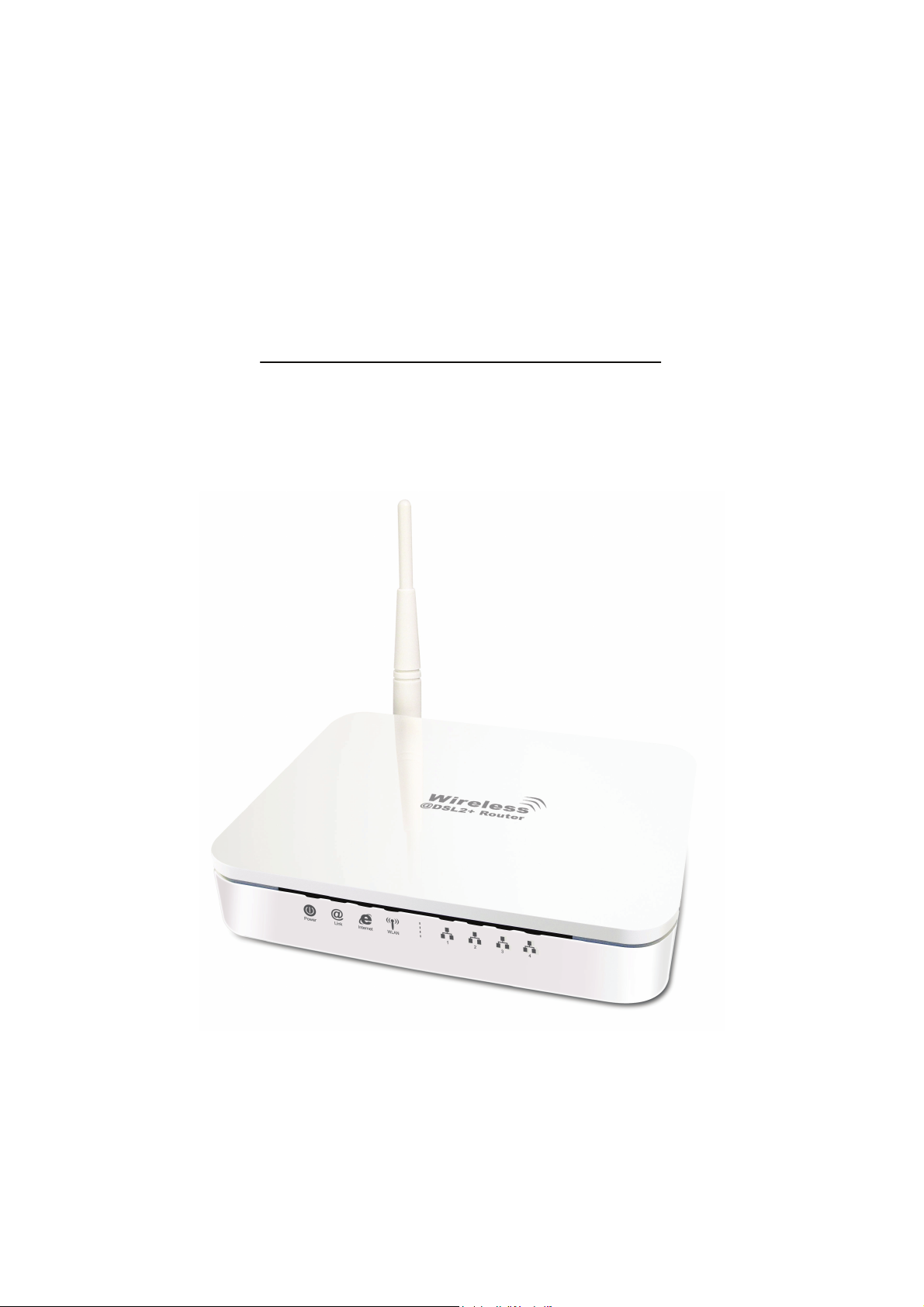
1.3 Product Description
WLAN ADSL2+ Router is a low cost, high performance and high-speed device that provides a
full rate ADSL2+ Router with the superb reliability and a complete solution for home and office
router. WLAN ADSL2+ Router can have a maximum downstream data rate of up to 24Mbps
and an upstream of up to 1Mbps. When configured as a DHCP server, it will assign IP address
to every connected PC and acts as the only externally recognized Internet device on your local
area network. With build-in NAT, WLAN ADSL2+ Router serves as an Internet firewall,
protecting your network from being accessed by outside users. You can safely enjoy the new
generation broadband Internet with WLAN ADSL2+ Router.
1

r
WLAN ADSL2+ Route
2.0 Specification
ADSL Standards supported
Compliant to ITU-T G.992.1 (G.dmt), G.992.2 (G.lite), G.992.3 (ADSL2), G.992.4 (splitterless
ADSL2), G.992.5 (ADSL2+) for Annex A, B
G.lite (G.992.2) with line rate support of up to 1.5Mbps downstream and 512Kbps upstream.
Supports Multi-Mode standard (ANSI T1.413, Issue 2; G.dmt (G.992.1); G.994.1 and
G.996.1(for ISDN only); G.991.1;G.lite (G992.2)).
Supports OAM F4/F5 loop-back, AIS and RDI OAM cells.
ATM Forum UNI 3.1/4.0 PVC.
Supports up to 8 PVCs (UBR, CBR, VBR).
Multiple Protocols over AAL5 (RFC 1483).
PPP over AAL5 (RFC 2364).
PPP over Ethernet (RFC 2516).
Wireless Ethernet 802.11g
With built-in 802.11g access point for extending the communication media to WLAN while
providing the WEP and WPA for securing your wireless networks.
Network Address Translation (NAT)
Network Address Translation (NAT) allows the translation of an Internet protocol address used
within one network (for example a private IP address used in a local network) to a different IP
address known within another network (for example a public IP address used on the Internet).
Universal Plug and Play (UPnP)
Using the standard TCP/IP protocol, the WLAN ADSL2+ Router and other UPnP enabled
devices can dynamically join a network, obtain an IP address and convey its capabilities to
other devices on the network.
10/100M Auto-negotiation Ethernet / Fast Ethernet Interface
This auto-negotiation feature allows the WLAN ADSL2+ Router to detect the speed of
incoming transmissions and adjust appropriately without manual intervention. It allows data
transfer of either 10 Mbps or 100 Mbps in either half-duplex or full-duplex mode depending on
your Ethernet network.
Dynamic DNS Support
With Dynamic DNS support, you can have a static hostname alias for a dynamic IP address,
Multiple PVC (Permanent Virtual Circuits) Support
Your WLAN ADSL2+ Router supports up to 8 PVC’s.
DHCP Support
DHCP (Dynamic Host Configuration Protocol) allows individual clients (computers) to obtain
TCP/IP configuration at start-up from a centralized DHCP server. The WLAN ADSL2+ Router
has built-in DHCP server capability enabled by default. It can assign IP addresses, an IP
default gateway and DNS servers to DHCP clients. The WLAN ADSL2+ Router can now also
act as a surrogate DHCP server (DHCP Relay) where it relays IP address assignment from the
actual real DHCP server to the clients.
2
r
r
r
r
WLAN ADSL2+ Route
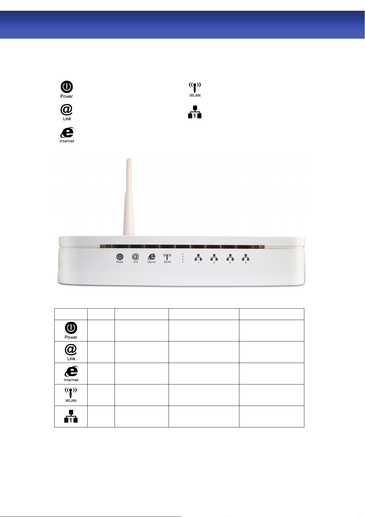
2.1 LED Meaning
Your WLAN ADSL2+ Router has indicator lights on the front side. Please see below for an
explanation of the function of each indicator light.
Power indicato
ADSL Link indicator
Internet Active indicator
Wireless Active indicato
Ethernet Active indicato
Table 1. LED function
Label Color On Flash Off
Green Ready Waiting for device ready Power Off
Green Connect to DSLAM Disconnect to DSLAM N/A
The device has a
Green
Green WLAN Ready Transmit / Receive Data WLAN Off
Green
The icons appear on the products are for application indication only.
The trademark or intellectual property is belonging to their respective owners.
WAN IP address
from ISP
Ethernet
Connected
Transmit / Receive Data N/A
Transmit / Receive Data
Ethernet
Disconnected
3
r
WLAN ADSL2+ Route
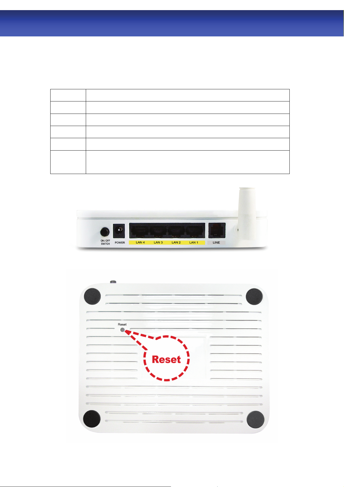
2.2 Connectors
Table 2 shows the function of each connector and switch of the device.
Table 2. Function / Description of Connectors
Connector Description
SWITCH
POWER
LAN1~4
LINE
RESET
Power Switch
Connects to your WLAN ADSL2+ Router 12Vac power adaptor
RJ-45 Jack (Ethernet Cable) connection to your PC, or HUB
Connects to your ADSL2+ line – for ADSL2+ Line input
Reset button. RESET the WLAN ADSL2+ Router to its default settings.
Press this button for at least 6 full seconds to start to reset it to its default
settings.
Figure1. Rear View of the WLAN ADSL2+ Router
Figure2. RESET button
4

r
2.3 Factory Default Settings
Before configuration, please refer to following default settings,
Web interface:
Username: admin
Password: 1234
LAN IP Settings:
IP Address: 192.168.1.1
Subnet Mask: 255.255.255.0
DHCP:
DHCP Server: Enable
WLAN ADSL2+ Route
5

r
WLAN ADSL2+ Route
3.0 Hardware Requirements
To use WLAN ADSL2+ Router, please have following hardware / accessories ready.
A PC with Pre-installed Ethernet Adapter (Required)
12Vac power adaptor (Included in the package)
RJ-45 Ethernet cable (Included in the package)
RJ-11cable (Included in the package)
3.1 Setting up the Hardware Environment
Please kindly refer to chapter 4.2 “Installation & Setup”
Note! Be sure that you are well insulated from any power source to avoid
electricity shock.
3.2 Powering on WLAN ADSL2+ Router
Please kindly refer to chapter 4.2 “Installation & Setup”
Note! Use only the manufacturer-approved power supply that shipped with the
WLAN ADSL2+ Router.
1. Connect the power to the WLAN ADSL2+ Router by plugging the power supply into
an appropriate electrical outlet.
2. If the Power LED is off, refer to “Troubleshooting” for information.
6

r
WLAN ADSL2+ Route
4.0 System Requirements
1. Pentium 200MHZ processor or above
2. Windows 98SE / Windows Me / Windows 2000 / Windows XP / Windows Vista and
Windows 7
3. 64MB of RAM or above
4. 25MB free disk space
4.1 Package Contents
For Annex-B WLAN ADSL2+ Router
1. WLAN ADSL2+ Router
2. CD-ROM (Software & Manual)
3. Quick Installation Guide
4. 1 x Telephone Cable (RJ-11)
5. Ethernet Cable (RJ-45)
6. Power Adaptor
7. Annex-B Splitter (Optional, with an extra RJ-11 Telephone cable)
For Annex-A WLAN ADSL2+ Router
1. WLAN ADSL2+ Router
2. CD-ROM (Software & Manual)
3. Quick Installation Guide
4. 1 x Telephone Cable (RJ-11)
5. Ethernet Cable (RJ-45)
6. Power Adaptor
7. Annex-A Splitter (Optional, with an extra RJ-11 Telephone cable)
7
r
WLAN ADSL2+ Route
4.2 Installation & Setup
Follow each STEP carefully and only go to the next step once you have completed the
previous STEP.
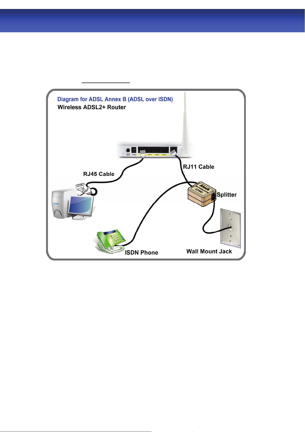
Connection of WLAN ADSL2+ Router
If you have an ISDN telephone line
connect the modem router as shown below:
1. Connect the supplied RJ45 Ethernet cable from your PC's Ethernet port to any of the 4
WLAN ADSL2+ Router's LAN Ports.
2. Connect the supplied RJ11 telephone cable from your home's telephone jack to the “LINE”
port of the supplied splitter. Connect another RJ11 telephone cable to the “MODEM” port
of the splitter and connect the other end of this cable to the LINE port of your WLAN
ADSL2+ Router.
cable from your home's telephone jack to the “LINE” port of your WLAN ADSL2+ Router.)
3. Connect a RJ11 telephone cable to the “PHONE” port of the splitter and connect the other
end to your telephone.
4. Connect the power adapter to the power inlet “POWER” of the WLAN ADSL2+ Router and
turn the “ON/OFF SWITCH” switch of your WLAN ADSL2+ Router on.
(If there is no option Splitter, please connect the supplied RJ11 telephone
8
r
WLAN ADSL2+ Route
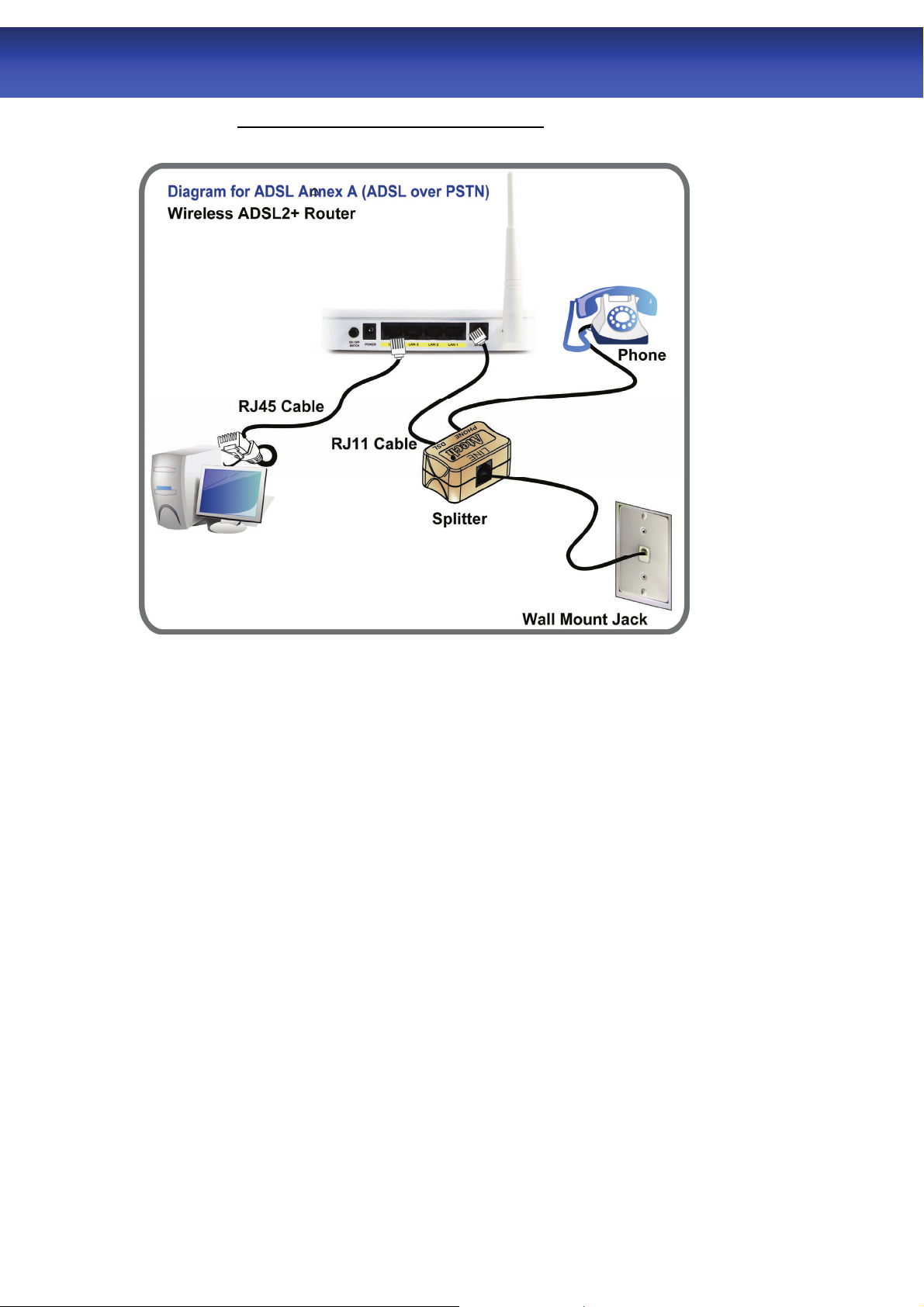
If you have a PSTN telephone line (normal analog line) connect the router as shown
below:
1. Connect the supplied RJ45 Ethernet cable from your PC's Ethernet port to any of the 4
WLAN ADSL2+ Router's LAN Ports.
2. Connect the supplied RJ11 telephone cable from your home's telephone jack to the “LINE”
port of the supplied splitter. Connect the other supplied RJ11 telephone cable to the “DSL”
port of the splitter and connect the other end of this cable to the “LINE” port of your WLAN
ADSL2+ Router. (If there is no option Splitter, please connect the supplied RJ11 telephone
cable from your home's telephone jack to the “LINE” port of your WLAN ADSL2+ Router.)
3. Connect a RJ11 telephone cable to the “PHONE” port of the splitter and connect the other
end to your telephone.
4. Connect the power adapter to the power inlet “POWER” of the WLAN ADSL2+ Router and
turn the “ON/OFF SWITCH” switch of your WLAN ADSL2+ Router on.
9

r
WLAN ADSL2+ Route
5.0 Configuration Procedures
Before starting the WLAN ADSL2+ Router configuration, please kindly configure the PC
computer as below, to have automatic IP address / DNS Server.
For Windows 98SE/ME/2000/XP
1. Click on “Start” -> “Control Panel” (in Classic View). In the Control Panel; double click on
“Network Connections” to continue.
2. Single RIGHT click on “Local Area connection”, then click “Properties”.
10
r
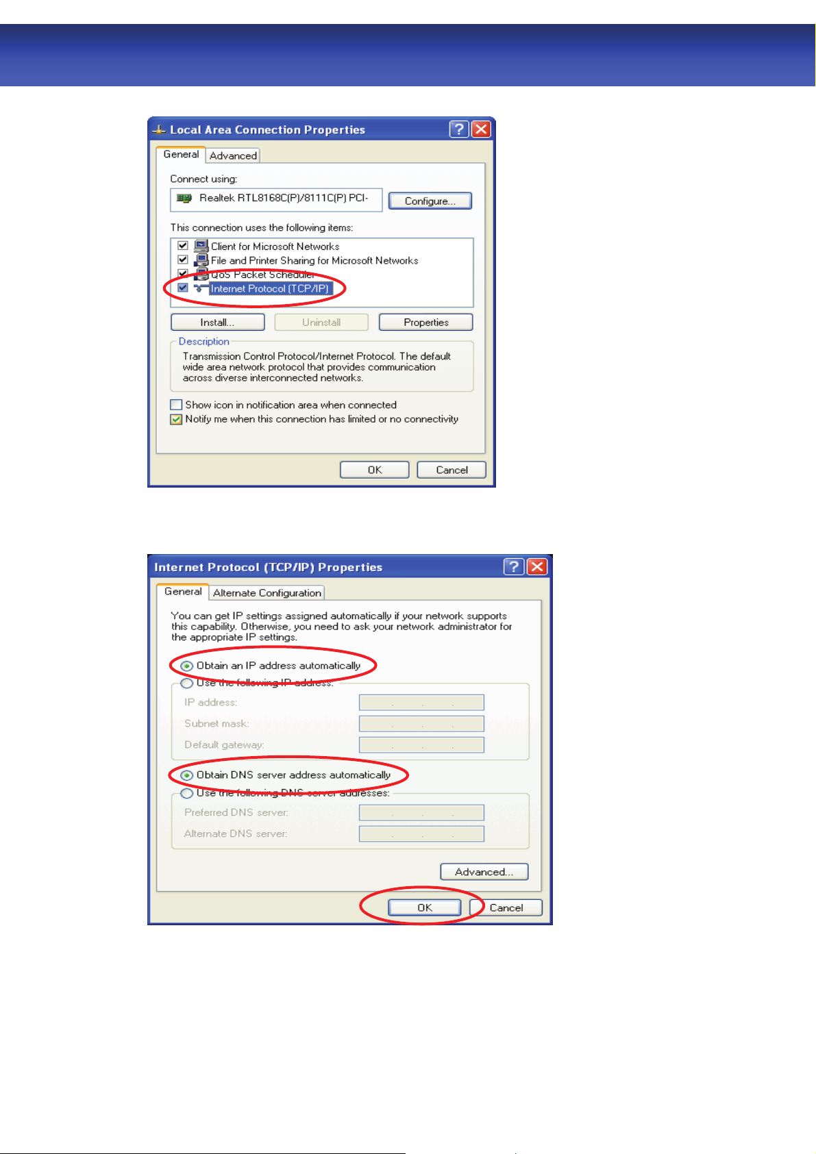
3. Double click on “Internet Protocol (TCP/IP)”.
WLAN ADSL2+ Route
4. Check “Obtain an IP address automatically” and “Obtain DNS server address
automatically” then click on “OK” to continue.
5. Click “Show icon in notification area when connected” (see screen image in 3. above)
then click on “OK” to complete the setup procedures.
11
r
WLAN ADSL2+ Route
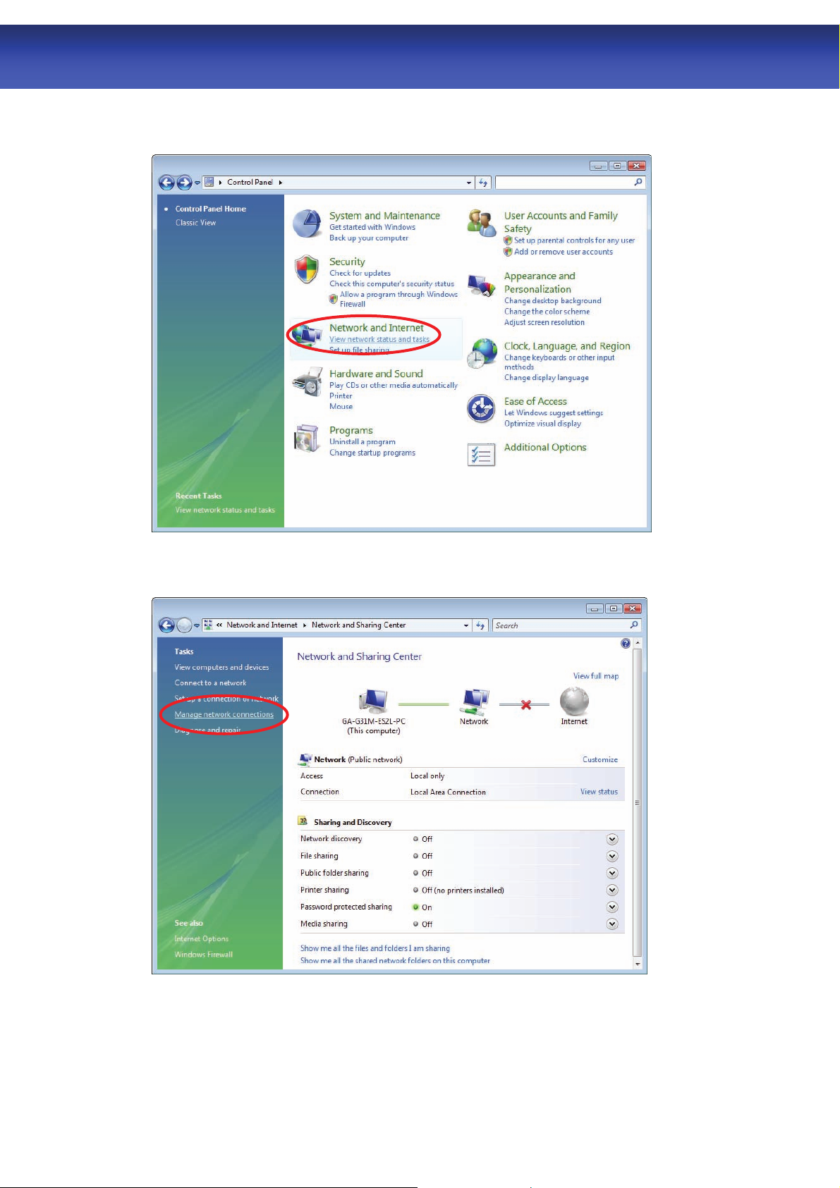
For Windows Vista-32/64
1. Click on “Start” -> “Control Panel” -> “Network and Sharing Center”.
2. In the Manage network connections, click on “Manage network connections” to
continue.
12

r
WLAN ADSL2+ Route
3. Single RIGHT click on “Local Area connection”, then click “Properties”.
4. The screen will display the information “User Account Control” and click
“Continue” to continue.
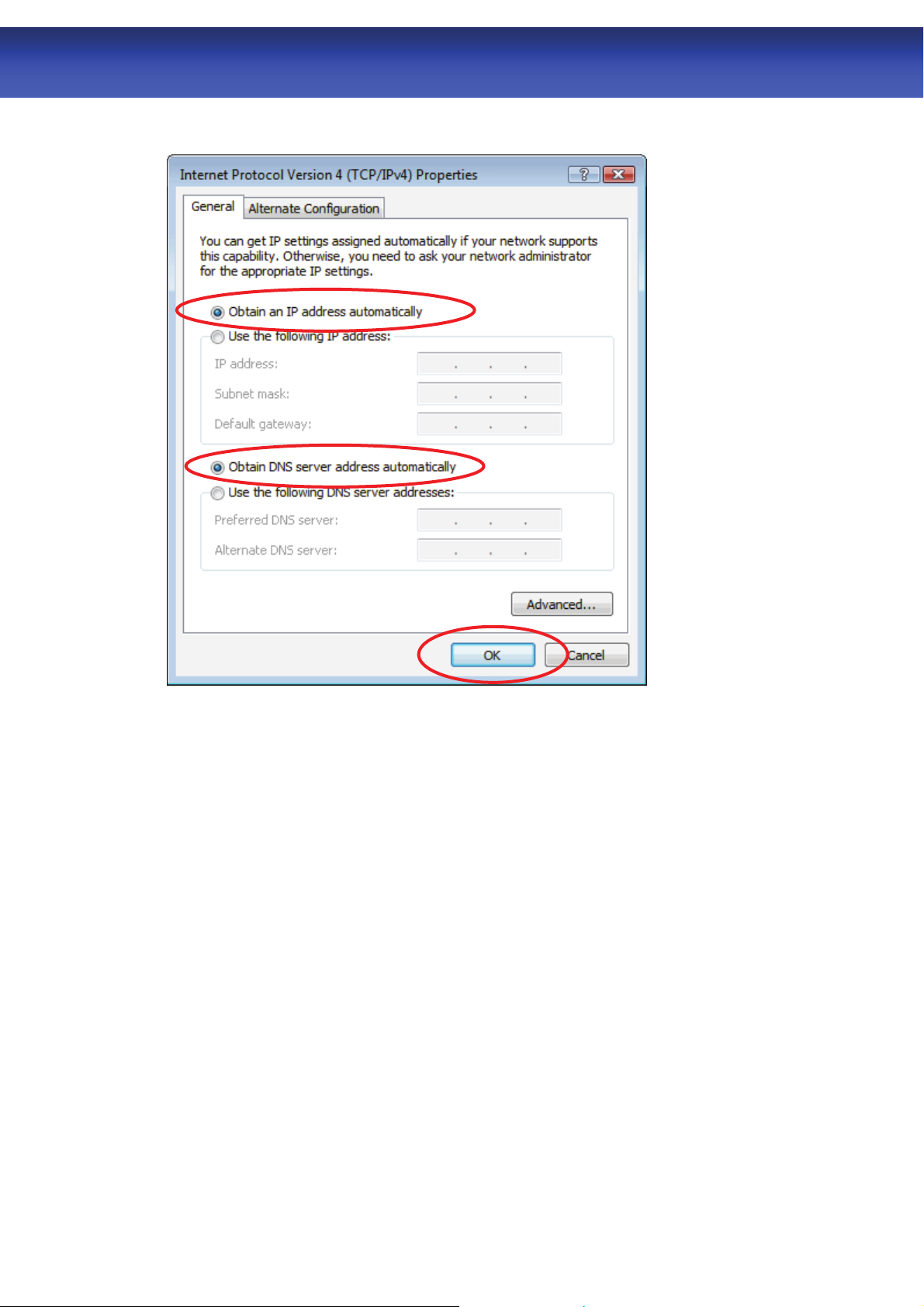
5. Double click on “Internet Protocol Version 4 (TCP/IPv4)”.
13
r
WLAN ADSL2+ Route
6. Check “Obtain an IP address automatically” and “Obtain DNS server address
automatically” then click on “OK” to continue.
14
r
WLAN ADSL2+ Route
For Windows 7-32/64
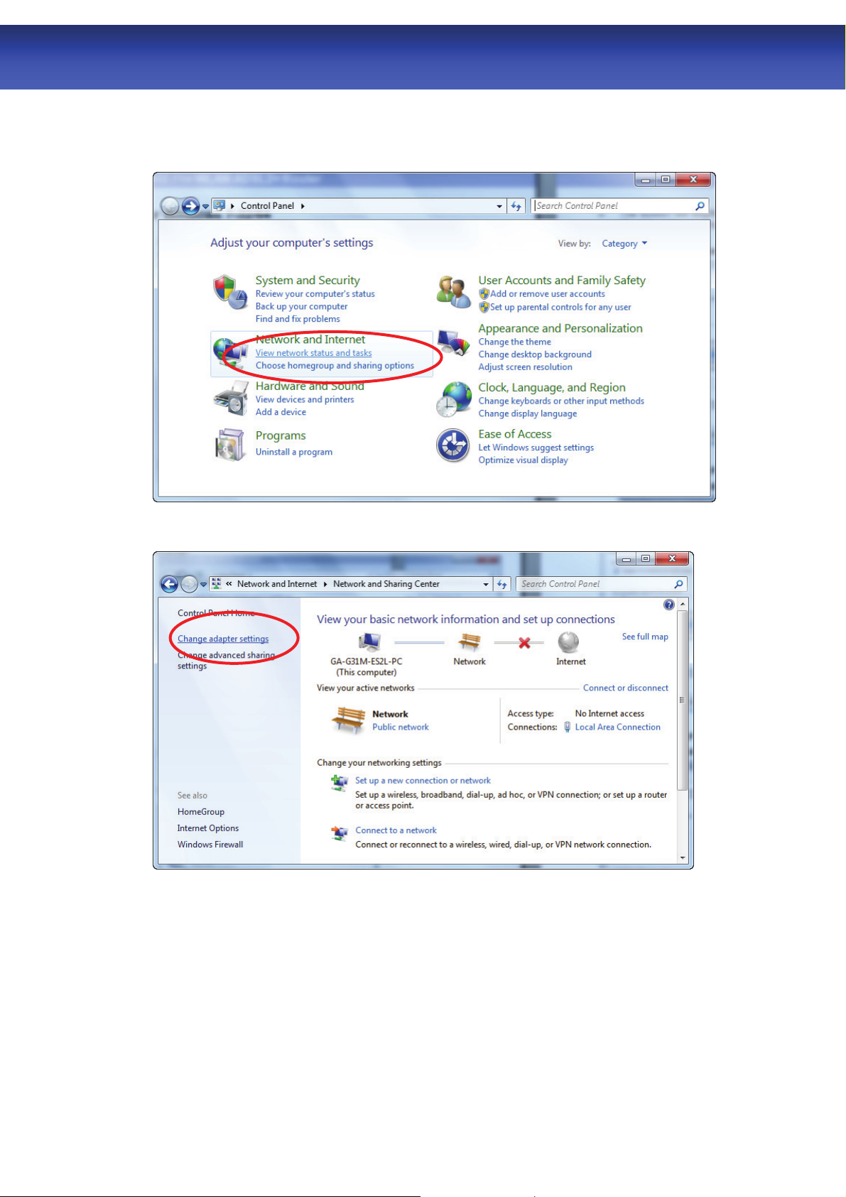
1. Click on “Start” -> “Control Panel” (in Category View) -> “View network status and
tasks”.
2. In the Control Panel Home, click on “Change adapter settings” to continue.
15
r
WLAN ADSL2+ Route
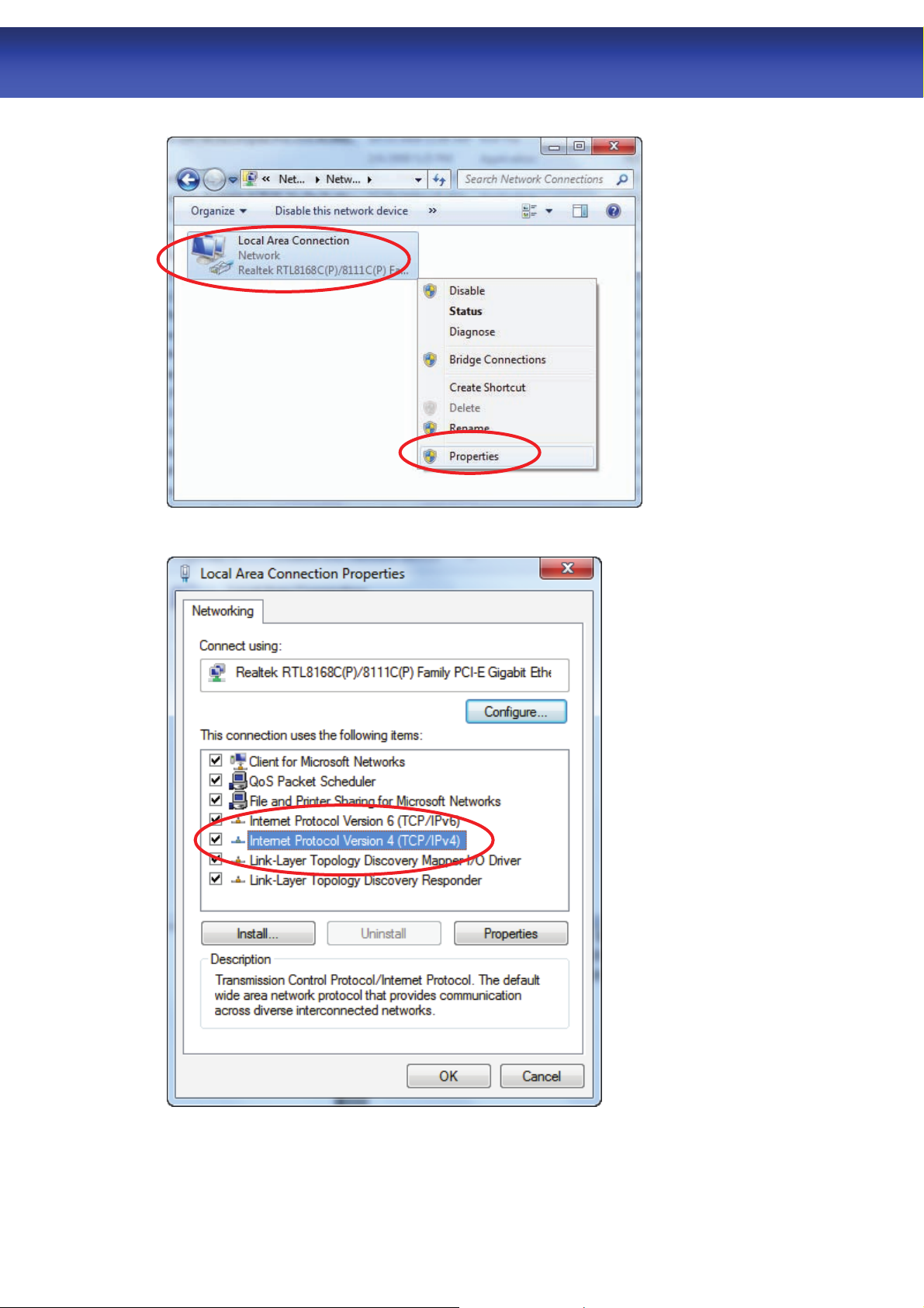
3. Single RIGHT click on “Local Area Connection”, then click “Properties”.
4. Double click on “Internet Protocol Version 4 (TCP/IPv4)”.
16
r
WLAN ADSL2+ Route
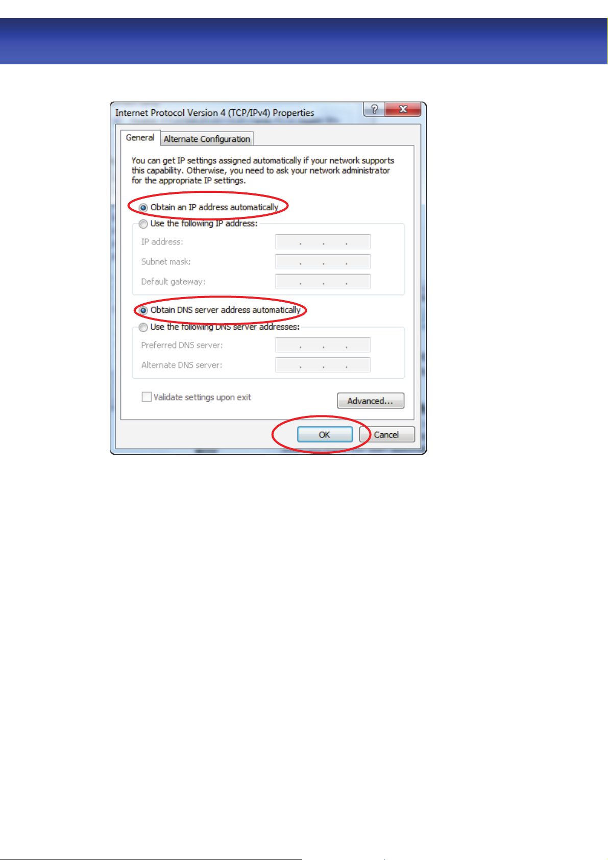
5. Check “Obtain an IP address automatically” and “Obtain DNS server address
automatically” then click on “OK” to continue.
17
r
WLAN ADSL2+ Route
6.0 WLAN ADSL2+ Router Configuration
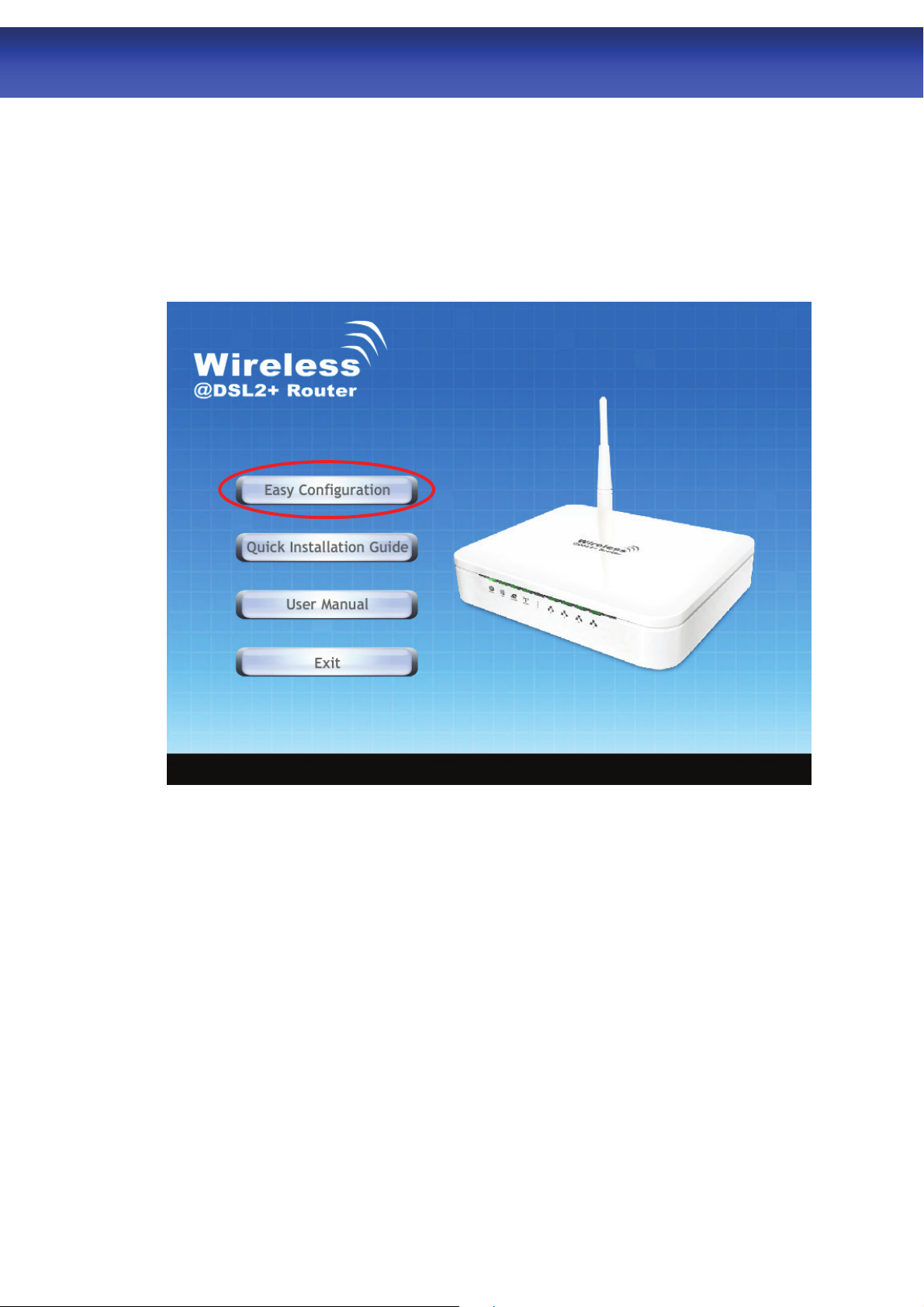
1. Please insert the supplied CD into your CD-ROM drive.
2. The CD should auto-start, displaying the window shown in 3. below. If your CD does not
start automatically, go to Windows Explorer, Select your CD drive and double click
“autorun.exe”.
3. To configure the device, please click “Easy Configuration”.
18
r
WLAN ADSL2+ Route
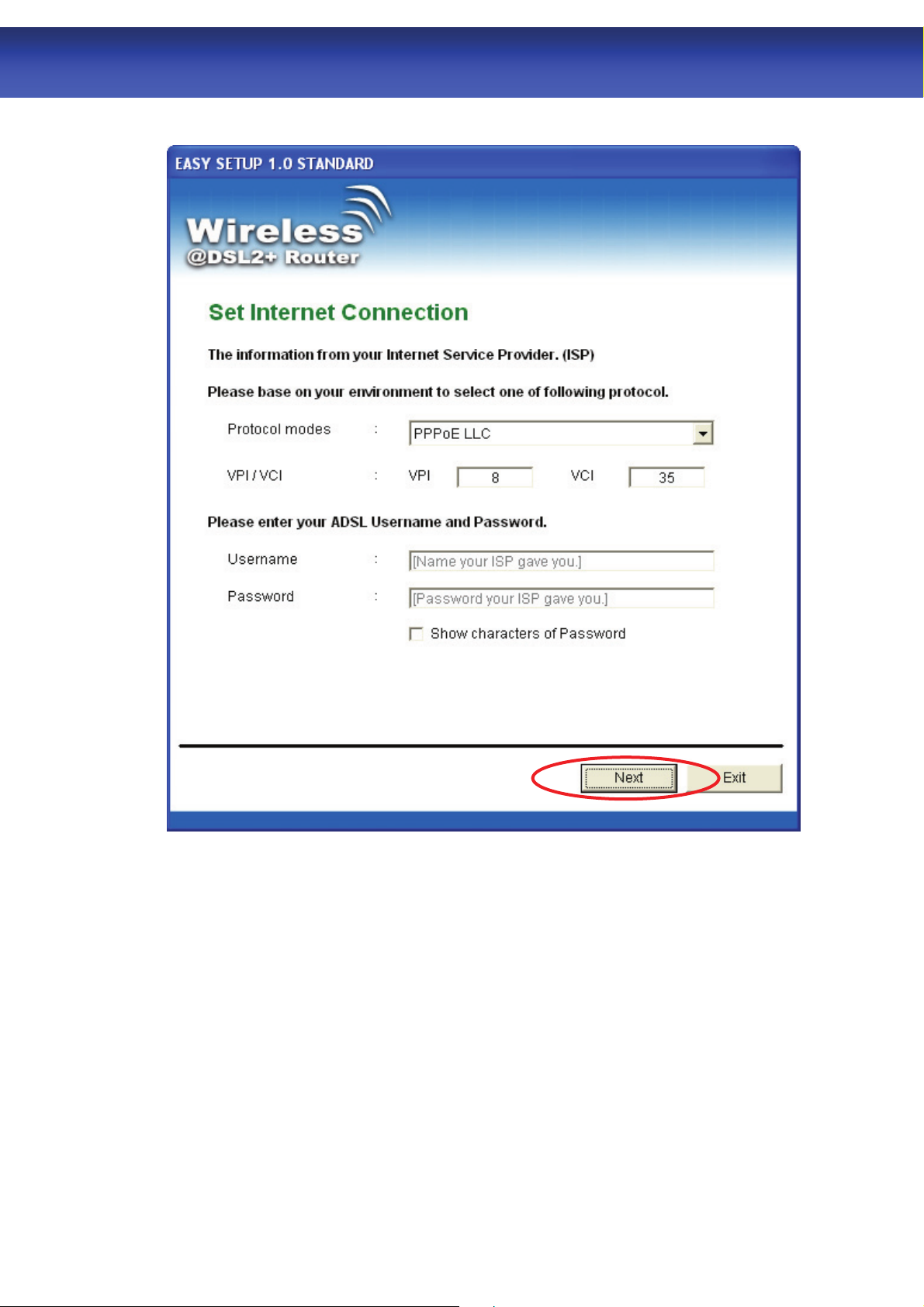
4. Enter the VPI, VCI, Username and Password your ISP (Internet Services Provider)
provided, and Protocol mode. Then press “Next”.
19
r
WLAN ADSL2+ Route
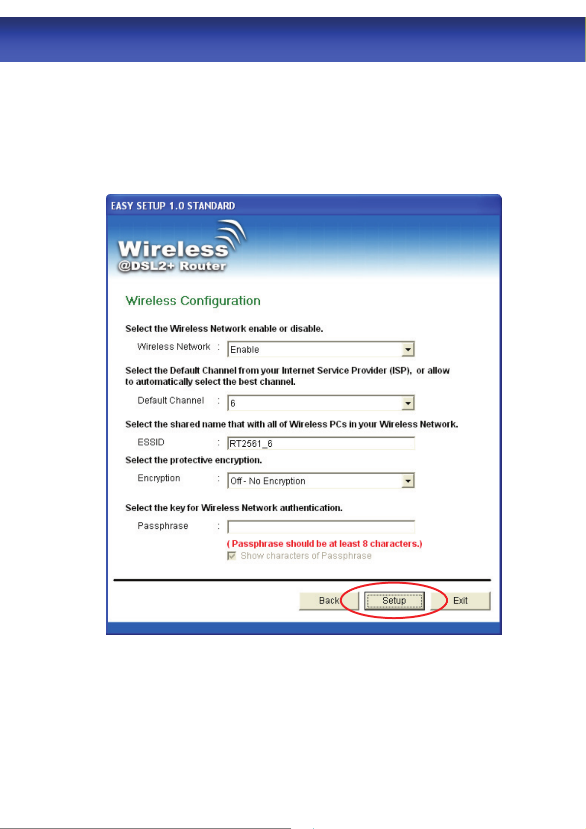
5. Please enter the “ESSID” and Wireless “Default Channel” if you want to change (the
default settings Network= Enable, ESSID = TW263R4, Default Channel=6).
6. Choose the Encryption type if necessary, as Off – No Encryption (Default) / 64 Bit
Encryption / 128 Bit Encryption / Wi-Fi Protected Access (TKIP) / Wi-Fi Protected Access2
(AES-CCMP) and WPA Mixed Mode. For example, you choose the WPA Mixed Mode type
and configure Passphrase.
7. Please click “Setup” button, when the procedure is completed, it will start to configure the
device for a while.
20
 Loading...