

HiRO Game of Drones Build Instructions
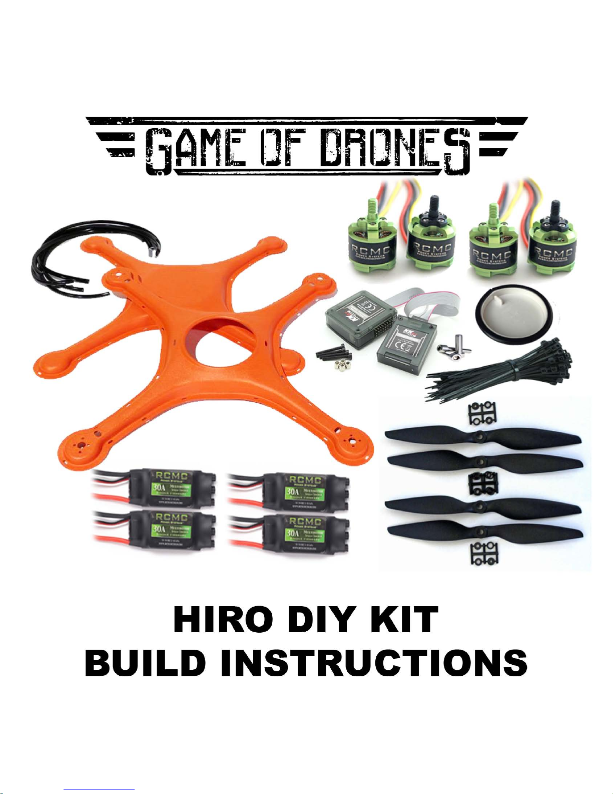

Congratulations on your purchase of the Game of Drones® Hiro Build-It-Yourself kit.
When you’re done, you’ll have your very own Hiro drone ready to bind to a transmitter. We designed this kit to be easy to use, fun, and educational. When you’ve completed the Game of Drones® Hiro Build-It-Yourself kit, you will not only have a drone
to y, you’ll also know more about how drones work. This may be your rst drone you
build, but don’t let it be your last. There’s a lot of building out there, and you’ve just
taken your rst step.
Content list
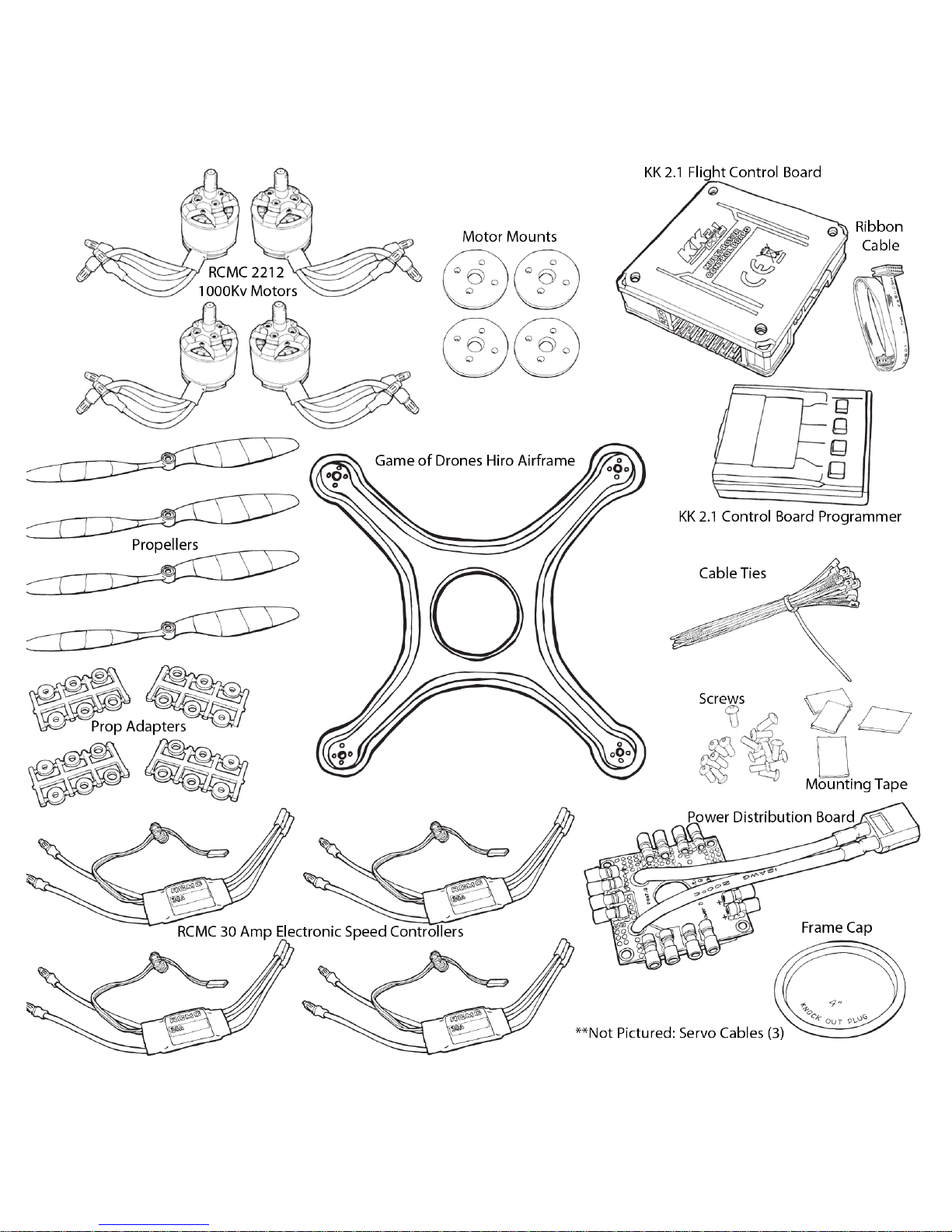
Your Game of Drones® Hiro Build-It-Yourself kit should include the following:
One Game of Drones® Hiro airframe;
Five lengths of plastic trim (four longer, one
shorter);
Cable ties;
Four wood motor mounts;
One KK 2.1 HC Multi-Rotor Control Board
with Programmer;
Two clockwise (CW) RCMC 2212 1000Kv V2
motors;
Two counterclockwise (CCW) RCMC 2212
1000Kv V2 motors;
16 small black screws;
5 servo wires;
1 grey ribbon cable;
Four RCMC 30Amp SimonK Firmware Electronic Speed Controllers (ESCs);
One power distribution board;
Four tabs of mounting tape;
Four propellers;
Four sets of propeller adapters;
One frame cap
Tools you’ll need:
Phillips screwdriver
Allen wrenches size 2 mm, 2.5 mm
Small-nose pliers
Wire cutters
Scotch or masking tape
Pliers or a ½-inch mini rachet
Pen
Other parts you’ll need:
RC transmitter
Receiver compatible with your transmitter
A 2200mAh 3S 30C LiPo battery with an
XT60 plug

Laying out your components
Estimated time to complete: 5 minutes
Remove the airframe from the box and separate the two sides. Lay them out and
become familiar with them.
The side with the hole in the center is the “top shell.” The “front” of your drone is
adorned with the “Game of Drones” sticker. Keep that in mind when you’re building.
The side without the hole is the “bottom shell.” The bottom shell is symmetrical, so
you don’t need to worry about a front or back.
Now, take your components out of the box and verify you have all the parts and pieces. If you nd something missing, contact us immediately.
Ready to build a drone?
Attaching motors to your frame
Estimated time to complete: 25 minutes
Start your drone-building odyssey by attaching the motors to your frame. You have
four motors and four arms. One motor is attached to each arm.
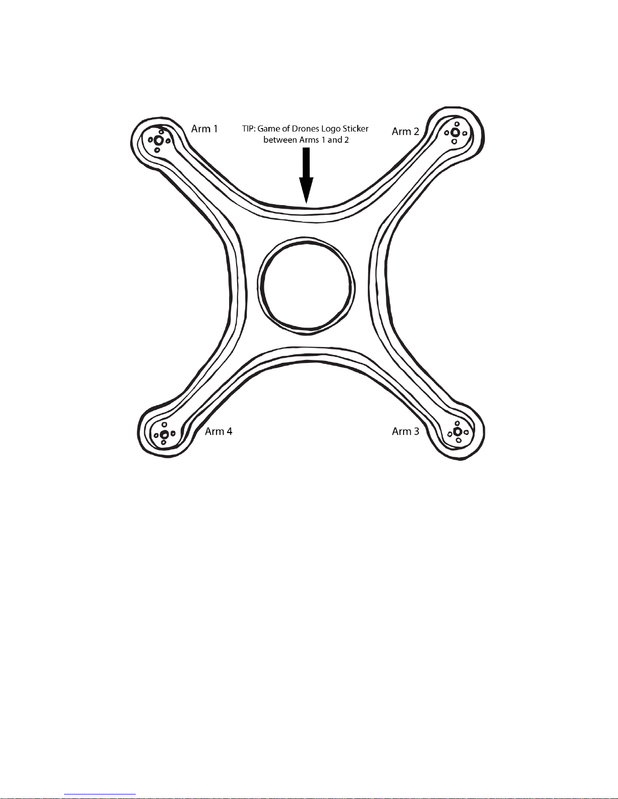
First take a moment to become familiar with your arms. Not the ones on your body;
the ones on your frame. Arm 1 is a friend, and you and it will spend a lot of time together. After you’ve identied Arm 1 through 4, use a small piece of tape and a pen
to number your arms so you can easily nd them later.
Pull out the box of two motors with black cap screws, the box of two motors with
green cap screws, the four wood motor mount disks, and the baggie of small black
screws.
Using your allen wrench, attach the two counterclockwise (green-capped) motors to
Arm 1 and Arm 3, and the two clockwise (black capped) motors to Arm 2 and Arm 4.

Starting with your old friend, Arm 1, place one of the wood motor mount disks inside the
frame and make sure all the holes on the disk align with the holes on the frame. The holes
are not in a perfect square, so if they don’t align, turn the mount 90 degrees and look again.
Eventually, you will get the mount so the holes all line up. Then use one of the small black
screws to secure the mount to the frame, screwing in until just the tip of the screw can be
seen coming through the top of the frame.
This step is a bit ddly and can be challenging the rst time you do it, but once you get the
hang, the other three will go on fairly quickly.
NOTE: DO NOT USE LOCTITE OR ANY SCREW
ADHESIVE ON YOUR SCREWS. We promise the
Screw Gods will not smite you and send your
motor inging o your frame if you don’t.
The motor mount was specially designed to
grip your screws and help prevent the need
for Loctite. If you do use Loctite, however, the
Frame Gods, who are division of the Plastics
and Chemistry Gods, will reign down cracks
on your frame. (That’s our way of saying the
chemicals in Loctite interact badly with the
plastics in the frame. So don’t do it.)

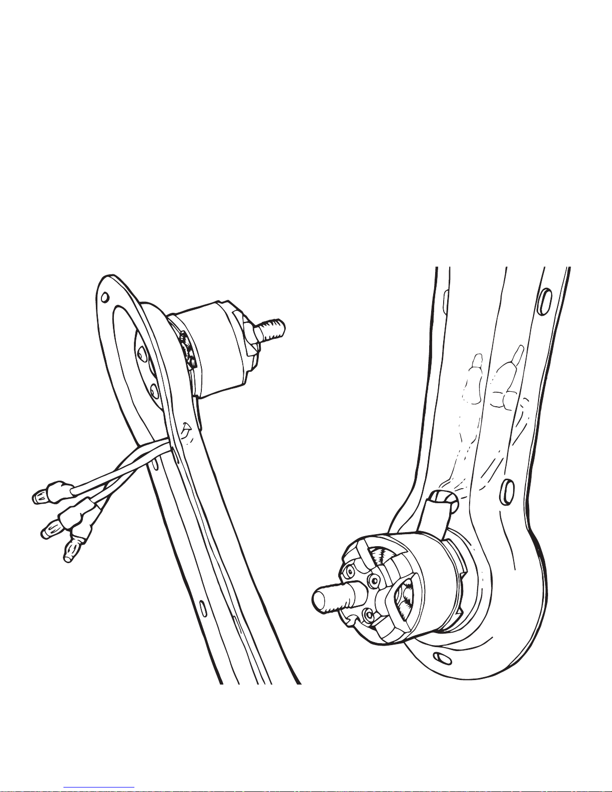
Then get a CCW motor (double check you’ve got the right one!) and align it so its wires
are pointed toward the center of the frame. Then line up the screw hole in the bottom of
the motor with the tip of the screw sticking out of your frame. Screw in the motor until it
is rm, but not so rm you can’t swivel the motor a bit to get the other three holes to line
up. Then screw in the other three screws.
Once you’ve got all four screws in
place, go back and tighten all four
screws rmly but not too tightly.
The head of the screw should be
ush with the wood mount. DO
NOT OVERTIGHTEN. If you screw
in as hard as possible, you’ll drive
the screw into the motor’s internal
parts and permanently damage it.
If you’re sinking the screw into the
wood, you’ve gone too far. Just a
rm t is good.
Do this for all four motors, making sure your CCW motors go on Arm 1 and Arm 3 and your
CW motors go on Arm 2 and Arm 4.
Now string all the wires coming out of the motors through the little slot in the frame next to
the motor. It’s easiest to string these through one at a time rather than all three at once.
Mounting your Control Board to your Power Distribution Board
Estimated time to complete: 10 minutes
Set your frame aside and get out your KK 2.1 Control Board (The one that has a “Multi-Rotor
Control Board” sticker) and your Power Distribution Board. Inside the Control Board box
you’ll nd four long black bolts with little silver nuts. Now take a moment to get familiar with
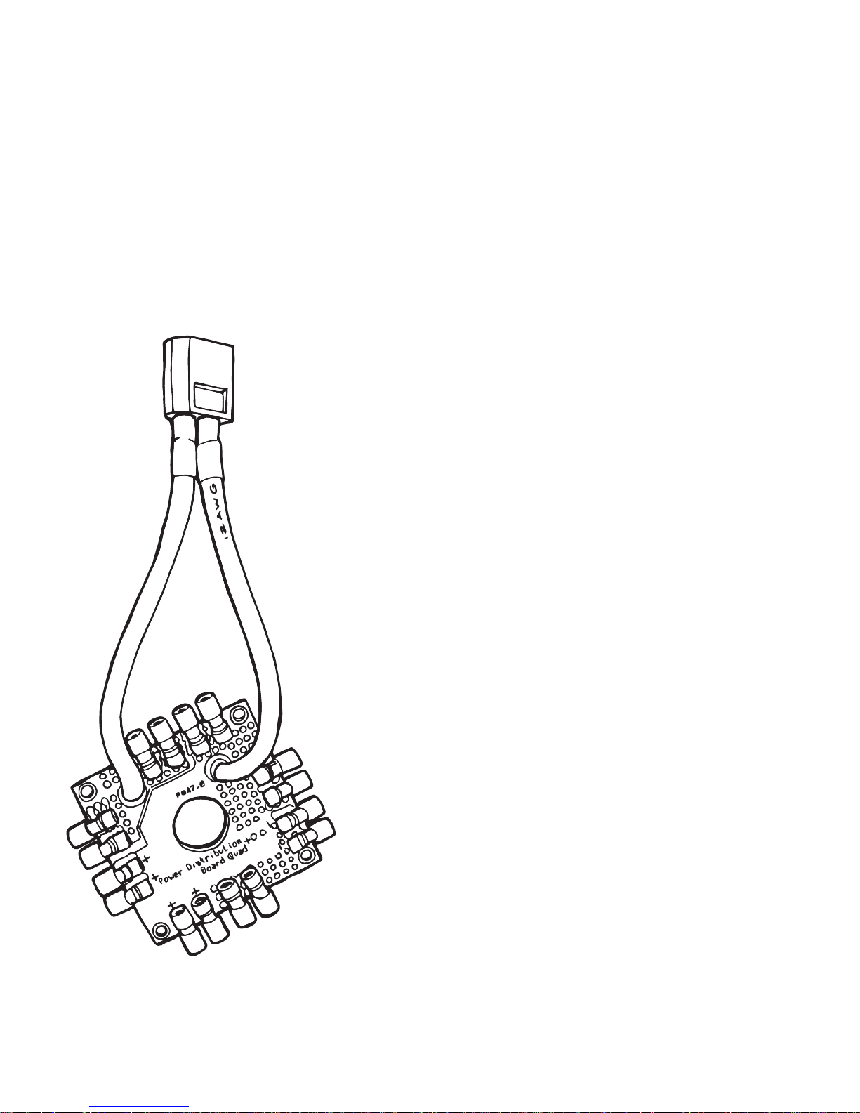
Grab your Power Distribution Board and you’ll
see a thick red and black wire with a yellow tip
coming o of it. This is your power cable, which
will connect to your battery. You’ll need to make
your Power Distribution Board as at as possible,
so split the red and black wires apart and orient
the wires so the black wire is to the left of the
plugs closest to where it attaches to the board
and the red wire is to the left of the plugs closest
to where that wire is attached.
NOTE: If you squint, it looks like a little heart.
your Control Board. On the bottom of its case
you’ll see a small arrow and the word “forward.”
On the top is a label that reads “Multi-Rotor
Control Board.”
Place your Control Board on the table with the
label-side up and the forward arrow pointing
away from you. You’ll know you’re in the right
position if the words on the label are right-side
up. If they’re upside down, spin it around. If you
are seeing the arrow, ip it over.
 Loading...