

HiRO 160 Q Installation Instructions Manual
Version 1.01
Installation instructions
for stair lift
HIRO 160 Q

1. Contents
2
Contents
1. Contents ............................................................................................................................. Page 2
2. Key to symbols .................................................................................................................. Page 3
3. Assembly and installation procedure HIRO 160 Q .......................................................... Page 4
3.1 Tools ............................................................................................................................ Page 4
3.2 Preparations for work.................................................................................................... Page 5
3.3. Installation of guide rails ............................................................................................... Page 7
3.4 Installation of drive unit ............................................................................................... Page 12
3.5 Installation of chair ...................................................................................................... Page 18
3.6 Installation of upper/lower stops ................................................................................. Page 20
3.7 Setting and testing the safety switches ....................................................................... Page 24
Please keep these instructions for further reference!
2. Key to symbols
3
Key to symbols
Caution! Risk of personal injury!
Attention! Risk of material damage!
Note
HIRO LIFT Hillenkötter + Ronsieck GmbH
Tel. + 49 / 521/ 9 65 52- 0 Fax + 49 / 521/ 9 65 52- 40 Meller Straße 6
Service + 49 / 521/ 9 65 52-39 D 33613 Bielefeld
Email: info@hiro.de . Internet: www.hiro.de
Germany

3. Assembly and installation procedure HIRO 160 Q
4
3.1 Tools
The following tools are required for assembling and
installing a HIRO 160 Q stair lift:
• Percussion drill
• Percussion drill bits 6 - 14 mm
• Power drill
• Set of drill bits and taps for metric thread sizes
M4 - M12
• Power screwdriver
• Angle grinder
• Vacuum cleaner
• Set of socket spanners
• Set of open-ended/ring spanners
• Torx spanner T40
• Set of screwdrivers
• Electric power tool
• 2 x chain hoist 250 kg
• Set of metric Allen keys
• Hydraulic jack
• Spirit level
• Tape measure

3. Assembly and installation procedure HIRO 160 Q
5
3.2 Preparations for work
The lift unit is supplied in the following packages:
1. Drive unit
2. Seat
3. Cover panels
4. Guide rail beams
5. Production parts list, lift unit drawing with list of
supports and fixing materials for the stops
6. Guide rail supports
7. Fixing brackets and screws for anchoring guide
rails and supports
8. Wall mount for charger unit
9. Electrical accessories kit with charger unit,
charging cable, charging bars, fixing materials,
magnets and bolts and screws
10. Lift unit drawing and documentation
11. Circuit diagram, list of parameters and
operating instructions for the control
12. Instructions and acceptance inspection
documentation
3. Assembly and installation procedure HIRO 160 Q
6
Before starting installation work, please check
whether the dimensions given in the lift unit drawing
agree with the actual dimensions on the installation
site.
Check against the lift unit drawing and the
production parts list to ensure that the lift unit
delivered is complete.
Arrange the guide rail supports according to length
and position.
Please refer to the list of supports to see which
support length is required in each case. The
position of the supports is shown in the lift unit
drawing.
All the dimensions relevant for the installation work
are shown in red on the lift unit drawing.
All dimensions on the lift unit drawing refer to the
centre of the guide rail tube.
The guide rail supports are shown as S1/S... in the
lift unit drawing and are indicated in the parts list
with their various lengths.
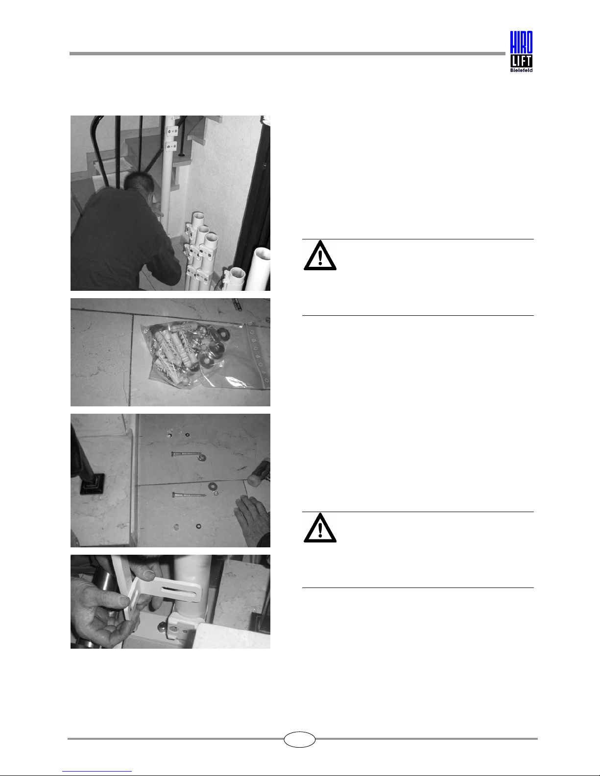
Take the fixing brackets out of the enclosed
accessories kit and take out the accompanying
screws for assembling the supports.
Place the guide rail supports, guide rail brackets,
clips and fixing screws on the staircase treads
specified in the lift unit drawing.
3. Assembly and installation procedure HIRO 160 Q
7
3.3 Installation of guide rails
In lift units where the guide rails are fixed to the
wall only, be sure to use through bolts or wall
anchors.
Where guide rails are fixed to the wall, the fixing
points are shown as W1 - W... on the lift unit
drawing.
If the guide rails are to be fixed to concrete, only
approved adhesive anchors or stud bolts must be
used.
When fixing the supports, they must be supported
with a bracket attached to the nearest wall
wherever possible.
The lift unit drawing specifies the distances
between the guide rail and the staircase tread.
Lay the lower end of the guide rail track on the
floor. The lower edge of the guide rail track is
specified in the lift unit drawing from the outer
edge of the staircase tread (zero point).
For lifts with a horizontal travel path, the height
dimension specified is that of the guide rail track.
Adjust the guide rail track with the supports loosely
attached or using a hydraulic jack.
Particular attention must be paid to ensure that the
guide rail track and the supports are properly
anchored.
3. Assembly and installation procedure HIRO 160 Q
8
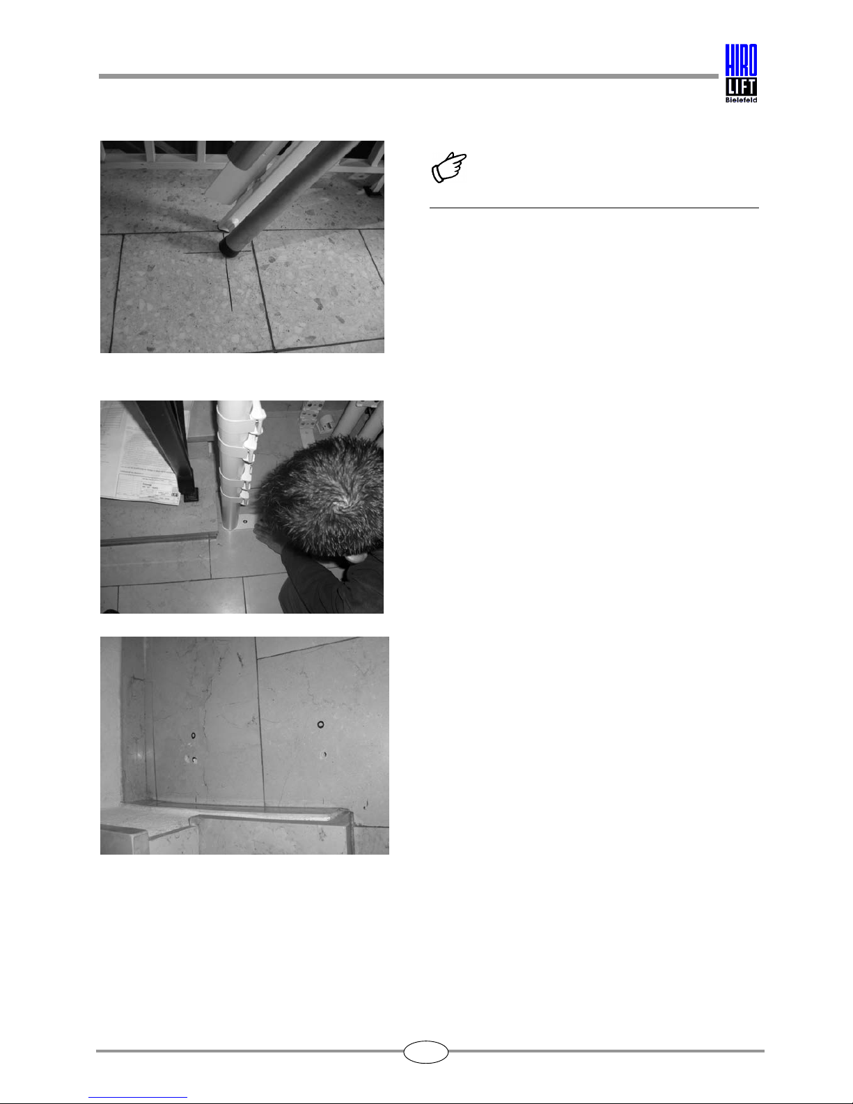
Note!
Before installing the guide rails, the lower guide rail
cap must first be attached.
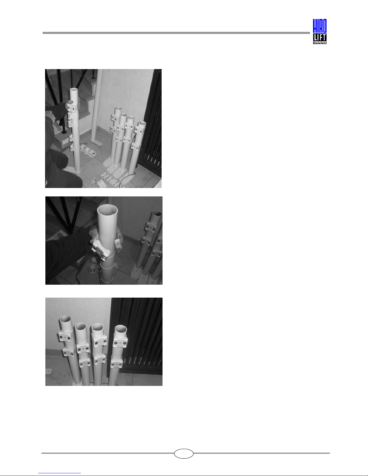
For lift units with guide rail supports in the stairwell,
the supports must be fitted first as shown in the lift
unit drawing.
The dimensions for each of the supports are given
in the lift unit drawing.
All dimensions refer to the centre of the tubular
supports.
Mark the positions of the supports.
Place the supports on the pencilled in positions
and mark the position of the screw holes.
3. Assembly and installation procedure HIRO 160 Q
9
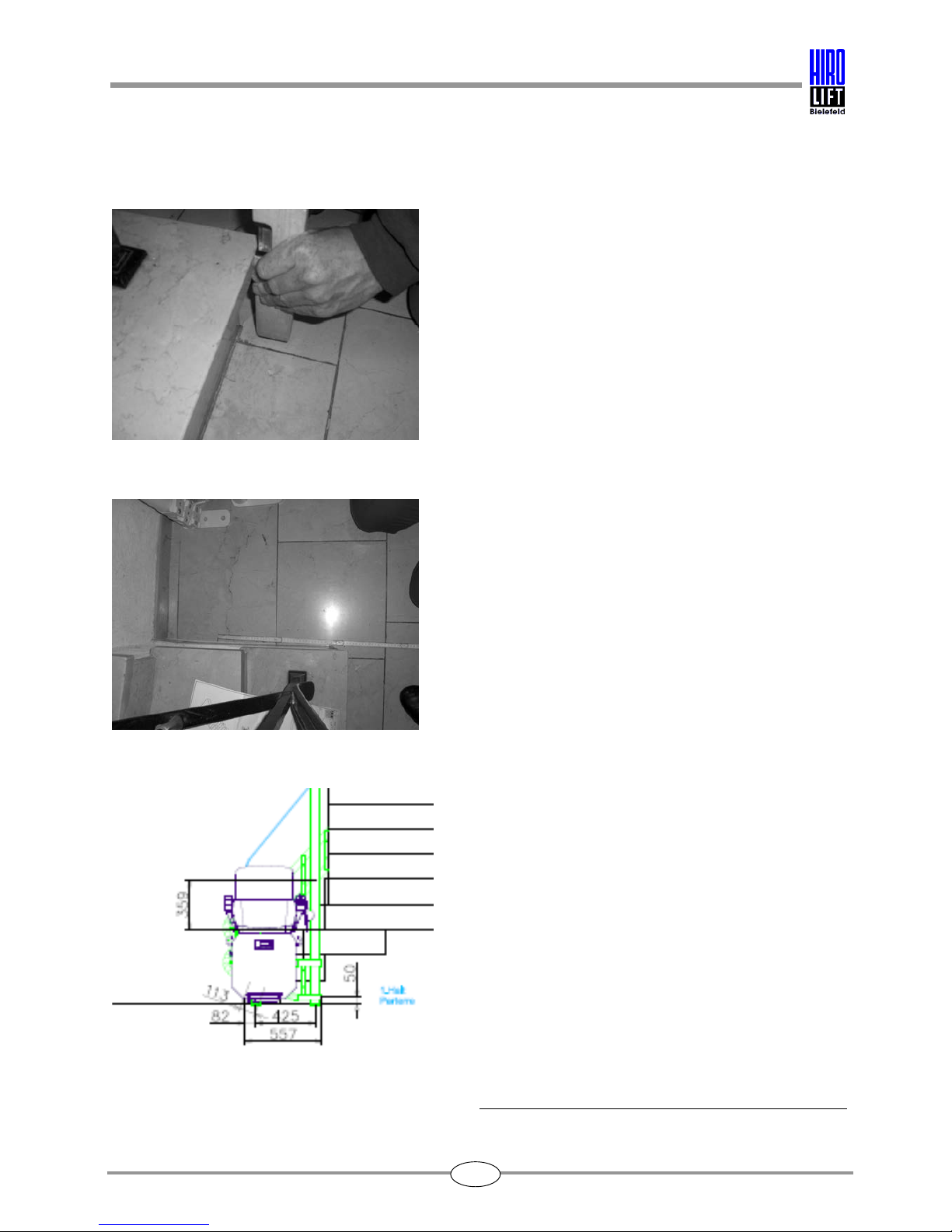
The size of drill bit to be used depends upon the
fixing materials contained in the enclosed
accessories kit and shown in the list enclosed with
the accessories.
Attention!
Before drilling, ensure that there are no cables or
underfloor heating present in the area concerned.
Different types of fixings are possible depending
on the subsurface and the floor covering.
Attention!
If the subsurface is loose, then the supports must
be fixed to concrete.
 Loading...