

Page 1
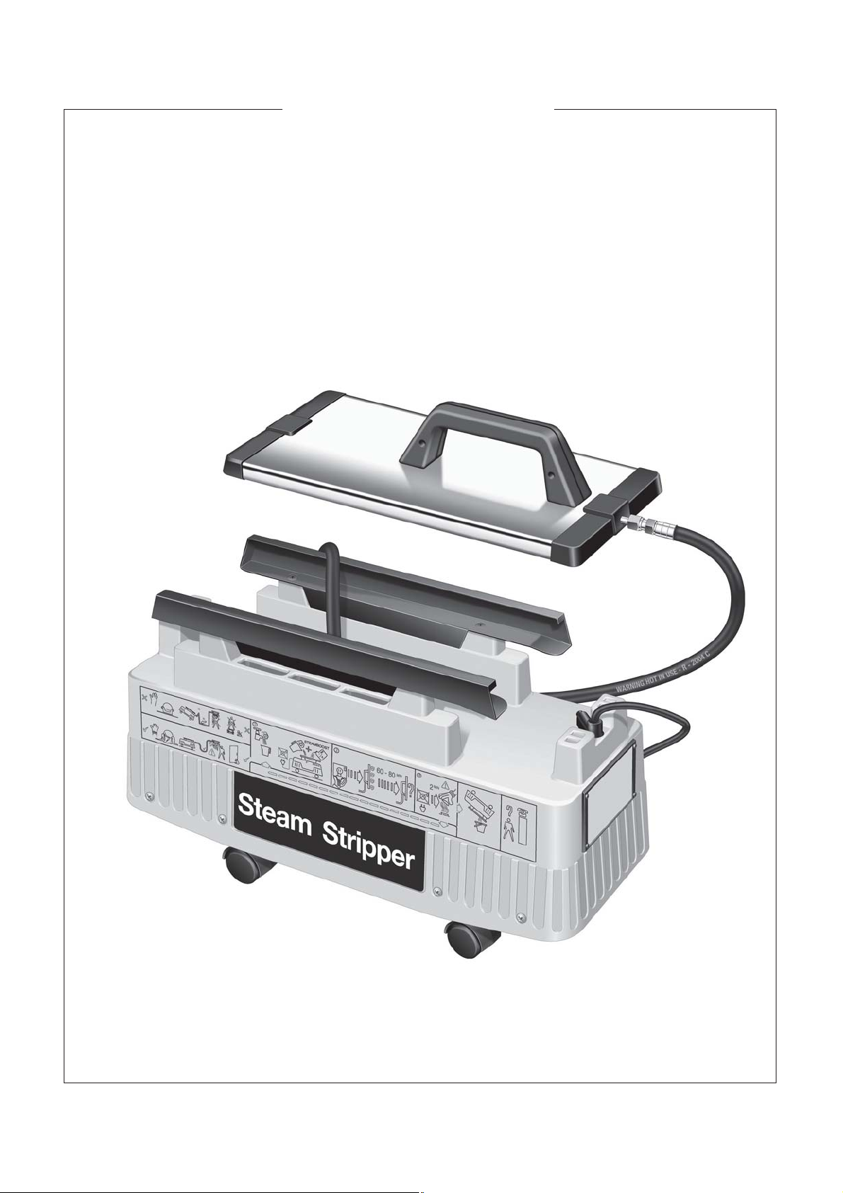
ABC
STEAM WALLPAPER STRIPPER
MODEL HTW-5
PRINTED IN THE UK
NOVEMBER 2011
OWNERS MANUAL & OPERATING INSTRUCTIONS
© Hiretech
REF. 73 PART # 007716
Page 2
NORTH AMERICAN SAFETY INSTRUCTIONS
WARNING: This steam wallpaper stripping machine must be grounded.
This steam wallpaper stripping machine shall be grounded while in use to protect the operator
from electric shock. The machine is provided with a three-conductor cord and a moulded threecontact grounding type attachment plug to fit the proper grounding type receptacle. The Green
(or Green and Yellow) conductor in the cord is the grounding wire. Never connect this wire to
other than the grounding pin of the attachment plug.
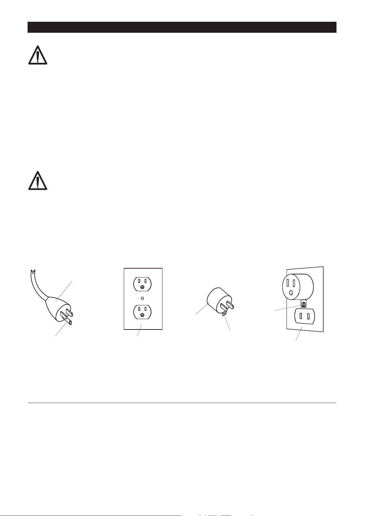
This steam wallpaper stripping machine is provided with an attachment plug as shown in sketch
A. It is intended for use on a nominal 120 volt circuit. If a properly grounded receptacle as shown
in sketch A is not available, an adaptor as shown in sketch 'C' should be installed as shown in
sketch B if the outlet box that houses the receptacle is grounded. Be sure to fasten the grounding
tab with a metal faceplate screw.
WARNING: Steam under pressure and hot surfaces.
DO NOT remove or tamper with the steam cap when in operation. If a fault occurs allow steam
stripper to cool for a minimum of 2 minutes. Follow instructions detailed in this manual for fitting
and removing the steam cap.
ATTACHMENT PLUG
GROUNDING PIN
COVER OF GROUNDED
OUTLET BOX SKETCH ‘A’
SKETCH ‘C’
ADAPTER
GROUNDING
MEANS
METAL
SCREW
COVER OF GROUNDED
OUTLET BOX SKETCH ‘B’
This manual covers machines starting from the following serial numbers;
(220/240 Volt) (excluding North America)84264
84258 (110/120 Volt) (excluding North America)
75154 (110/120 Volt) (North America)
Page 3
CONTENTS
WARNING i
MAINS CABLE WIRING - PLUG i
SPARE PARTS i
SPECIFICATION 1
SAFETY 1
OPERATION 1,2
STRIPPING TECHNIQUE 2
OPERATING HINTS 2
MAINTENANCE AND SERVICING 2
FAULT FINDING 3
HTW-5 PARTS DRAWING 4
(excluding North America)
HTW-5 PARTS DRAWING 5
(North America only)
HTW-5 PARTS LIST 6
DECLARATION OF CONFORMITY 7
SERVICE & REPAIR 8
DEALER LIST 9
HTW-5 CIRCUIT DIAGRAMS 7
WARNING
For safe operationof this machine, read and understand all instructions. Look for the ‘warning/caution’ symbol.
This symbol means that if you do not follow the instructions injury can occur to the operator and
damage to the machine and work surface may result.
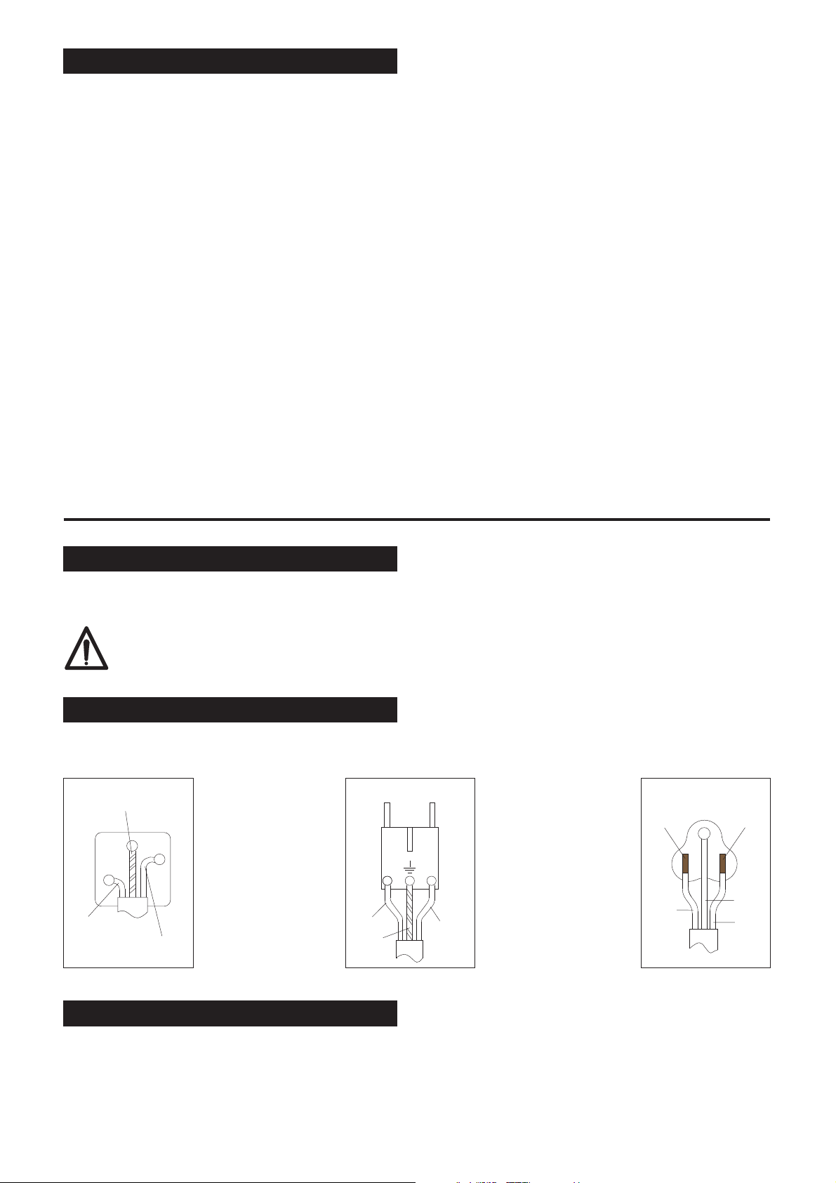
MAINS CABLE WIRING - PLUG
UNITED KINGDOM
GREEN/YELLOW
(E - EARTH)
EU
NORTH AMERICA
BRASS
TERMINAL
SILVER
TERMINAL
GREEN
WHITE
BLUE
(N - NEUTRAL)
BROWN
(L - LINE)
BLUE
GREEN/
YELLOW
BROWN
BLACK
SPARE PARTS
Use Hiretech genuine spare parts only for service and repair. Use of non-approved parts will void the product
warranty. See the back cover of this manual for the terms and conditions of the Hiretech Limited Warranty.
Hiretech reserves the right to make changes or improvements to it's products without prior notice.
®
®
®
i
Page 4

SPECIFICATION
The Hiretech Steam Team® Steam Stripper will
remove multiple layers of wallpaper and painted
Anaglypta, foils and flocks, also papers covered in
paint, distemper or varnish.
Power Supply: 110/120 V~ or 220/250 V~
®
Check data plate.
12. DO NOT use a power socket directly below the
area being stripped. Take precautions to prevent
water entering power sockets and light switches.
13. The power cable and steam hose must be
maintained in good condition.
14. Operate the steam stripper on a level surface DO
NOTuse this product as a step.
Heater Element: 1.4/1.6 kw or 2.2/2.5 kw.
Water Tank: 7 litres (1.5 gallons) capacity.
Weight Dry: 7.5 kg (16.5lbs).
CAUTION: Read the following Safety and
Operational notes before using your
Steam Team® Steam Stripper.
SAFETY
1. For your safety it is recommended that a residual
current circuit breaker (ground fault interrupter)
is used with this product.
2. Ensure the electrical supply conforms to that
detailed on data label of this product. If in doubt
consult a qualified electrician. The supply cable
must be earthed.
3. The steam generated by this product is
DANGEROUS. Keep children well away from
work site.
4. Ensure the steam hose is sound and securely
fitted before use and that it is not kinked or
becomes kinked or flattened in use.
5. NEVER remove filler cap on the steam tank when
the steam stripper is in operation or attempt to
adjust or tighten it if steam is seen to be escaping
from around the filler cap area. Disconnect from
power supply, allow to cool for a MINIMUM OF 2
MINUTES then check and refit the cap.
6. DO NOT attempt to move the steam stripper to a
new work site unless the power has been
disconnected and the machine has been allowed
to cool for a MINIMUM OF 5 MINUTES. To move
the steam stripper to a new work site lift by steam
plate rails only.
7. Ensure adequate ventilation of work site.
8. Use clean WATERonly to fill the steam tank.
9. NEVER operate the steam stripper without water.
10. Always disconnect from the power supply before
filling with water or when not in use.
OPERATION
1. Set up by clearing furniture from the work area.
Prepare for slight spillage, carpets and floors
must be protected. Roll carpets back or protect
with plastic sheet and dust sheet. Layout tools
required ready to start work.
2. Place steam stripper on floor or stable level work
surface near to the area to be stripped. Remove
the steam plate and lay out the steam hose and
power lead. DO NOT plug into power supply.
3. Remove the filler cap (see 11) and fill water tank
with clean hot or cold tap water to a maximum of
5cm (2") from top of tank. DO NOT over fill or
cover rubber safety valve located at the base of
the tank filling neck.
4. Replace the filler cap ensuring a correct fit.
NEVER force or attempt to over tighten the filler
cap (see 11).
5. Place the steam plate face up on the floor or work
surface which should be protected from
condensation when steam is first produced.
Alternatively place steam plate in a bucket or
large plastic container ready to collect water
which will have condensed from the steam in the
steam plate.
6. Plug in to a suitable power supply. The steam
stripper will switch itself on automatically. Allow
the steam stripper to heat the water until it turns
to steam, 10 to 30 minutes.
7. When steady jets of steam are produced the
steam stripper is ready to use. Lift the steam
plate above the steam stripper this will allow
water condensed in the steam hose from the
steam to run back into the water tank.
8. Now begin stripping (see Stripping Technique).
Continue using the steam stripper until the steam
stops, about 60 to 80 minutes. When the steam
stops the steam stripper is ready to be refilled.
The steam stripper will switch off automatically
when a low water level is reached. Of course you
can stop when ever you wish, just disconnect
from the power supply to switch off.
11. Take care when stripping paper from ceilings,
hot water may run from the steam plate.
1
Page 5

9. Refilling - DISCONNECT power supply and then
allow the steam stripper to cool down for a
MINIMUM OF 2 MINUTES.
10. ENSURE that the steam outlet holes in the steam
plate are clear and that the steam hose is not
kinked or flattened otherwise steam pressure in
the water tank will be maintained for a long
period.
11. The filler cap will be HOT, use a glove and do not
stand directly over the steam stripper when
removing it. Remove the cap at arms length. Lift
the filler cap lever and wait for excess steam to
vent. Then turn the cap anti-clockwise a
QUARTER of a turn only. If steam continues to
escape wait until it stops. ONLY THEN push
down the filler cap against spring pressure and
turn anti-clockwise a further quarter turn and pull
up gently to remove. To refit cap push down
against spring pressure and turn clockwise
approximately half a turn to stop position. Lower
filler cap lever to lock.
12. On finishing stripping allow the steam stripper to
continue to run until it switches off automatically.
Use a suitable container to catch the steam as it
condenses to water. When the steam stripper
switches off DISCONNECT power supply. Before
the steam stripper cools completely carefully
wipe down the body, steam hose andsteam plate
to clean.
13. Now allow the steam stripper to cool completely,
carefully store the steam hose and cable and
replace the steam plate. If work is completed and
the steam stripper is to be stored prepare the
machine as detailed in Maintenance and
Servicing.
STRIPPING TECHNIQUE
1. To help steam to penetrate more quickly and
speed up stripping perforate the wallpaper
covering with a Hiretech HTP-2 Wallpaper
Perforator. This is important where papers are in
multiple layers, painted over or are a vinyl type.
To save even more time perforate the covering
while waiting for the steam stripper to produce
steam.
2. Start at the top of the wall and work across and
down-wards. Place the steam plate against the
surface of the covering to be stripped.
will quickly learn how long you need to steam the
wallpaper to make it easy to strip.
5. Using the stripping knife in a downwards
direction at a 45 angle towards the steam plate,
begin to strip the covering from the top of the wall
and downwards all the time moving the steam
plate ahead of the area just stripped.
6. During stripping steam will be collecting in the
trough at the bottom of the steam plate and
condensing into water, which should be drained
away from time to time.
7. On completion of stripping the wall or ceiling
surface should be washed down to remove any
remaining pieces of covering and glue.
o
OPERATING HINTS
1. Care should be taken to check the condition of
the surface to be stripped. Should plaster on the
wall be loose, it is probable that when the
covering is removed the plaster or parts will
come away. Check by gently tapping the wall all
over, a hollow sound will indicate that the plaster
is loose. In such circumstances repairs should be
made.
2. Clean the steam stripper while it is still warm to
the touch. When cold any pieces of paper stuck
to the steam stripper will be difficult to remove.
3. When not in use ensure that the steam stripper is
empty and dry. Always store in a dry place.
MAINTENANCE AND SERVICING
1. On completion of work allow the steam stripper
to cool completely for a MINIMUM OF 4
HOURS. Remove the steam cap, turn the
machine over and drain off remaining water by
depressing the rubber safety valve located at the
base of the tank filler neck. Replace cap, wipe
down body and replace the steam hose, cable
and steam plate. Store in a dry place.
IMPORTANT. The filler cap and filler neck must
be maintained in good condition. Inspect both
regularly and ensure that the filler cap locates
properly and that both cap and filler neck are not
worn or damaged in any way. If damage is noted
do not use the steam stripper under any
circumstances, return it to you dealer for service.
3. Wait about 15 seconds, then move the steam
plate across the wall to the next area slightly over
lapping the area just steamed.
4. Loosen the edge of the covering with a stripping
knife. A broad blade stripping knife is
recommended for best results. If the covering is
difficult to strip allow a little longer to steam, you
2
Page 6

FAULT FINDING
FAULT
Machine does not heat up
ACTION
Check power supply and fuse in plug. If fuse
blows more than once return your steam stripper
to nearest dealer for service.
FAULT
Steam escaping from filler cap.
ACTION
Switch off and allow to cool for a MINIMUM OF
2 MINUTES. Using a glove and at arms length
carefully remove the filler cap. Inspect the filler
cap and filler neck for signs of damage or dirt. If
problem persists return machine to dealer for
service.
On no account attempt to adjust or tighten the
filler cap when the machine is switched on and
steam pressure remains.
FAULT
Machine overheats.
ACTION
Check machine is on a level surface. If fault
continues return to dealer for service.
FAULT
Escape of water and/or steam from below
machine as steam stripper heats up - safety vent.
ACTION
Machine has been over filled. Avoid over filling.
CAUTION Carpets and flooring should be
protected to avoid damage as water and liquids
are present at all times during stripping.
FAULT
Steam stops prematurely (could be
accompanied by an escape of steam from below
machine - safety vent).
ACTION
CAUTION steam hose or steam outlets could be
blocked. Disconnect from power supply. First
check to see if hose is kinked or flattened. If not
proceed with caution. Allow the machine to cool
for a MINIMUM OF 2 HOURS to allow steam
pressure to drop. Remove filler cap using gloves
at arms length.
If cause can not be found return the machine to
nearest dealer for service.
FAULT
Filler cap rotates past ‘stop’ position.
ACTION
CAUTION Do not use machine, return to nearest
dealer for service
3
Page 7
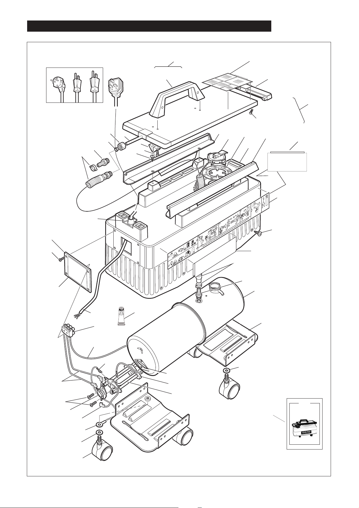
STEAM WALLPAPER STRIPPER HTW-5 (excluding North America)
All markets excluding North America
1
3
33
34
17
15
10
41
40
2
9
55
7
4
11
5
6
8
13
14
12
11
steam team
steam wallpaper stripper
Made with pride in the United Kingdom by
ABC
Part No. 007689
42
®
38
32
6
®
31
43
27
25
23
26
16
37
36
28
35
37
30
29
22
21
steam team
steam wallpaper strippersteam wallpaper stripper
Part No. 007626Part No. 007626
17
16
15
18
20
50
ABC
STEAM WALLPAPER STRIPPER
MODEL HTW-5
From Serial Number
75431 (220/240 Volt) & 75154 (110/120 Volt)
K
U
E
H
T
N
I
D
E
T
N
I
R
P
OWNERS MANUAL & OPERATING INSTRUCTIONS
© Hiretech
AUGUST2005
REF. 73 PART# 007716
19
Page 8
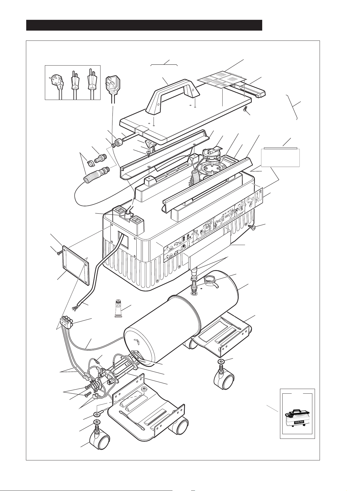
STEAM WALLPAPER STRIPPER HTW-5 (North America only)
STEAM WALLAPER STRIPPER HTW-5 (North America)
North America Only
1
3
33
34
17
15
10
41
40
2
9
55
7
4
11
5
6
8
13
14
12
11
steam team
steam wallpaper stripper
Made with pride in the United Kingdom by
ABC
Part No. 007689
42
®
38
32
6
®
31
43
27
25
23
26
16
37
36
28
35
37
30
29
22
21
steam team
steam wallpaper strippersteam wallpaper stripper
Part No. 007626Part No. 007626
17
16
15
18
20
50
ABC
STEAM WALLPAPER STRIPPER
MODEL HTW-5
From Serial Number
75431 (220/240 Volt) & 75154 (110/120 Volt)
K
U
E
H
T
IN
D
E
T
N
I
R
P
OWNERS MANUAL & OPERATING INSTRUCTIONS
© Hiretech
AUGUST2005
REF. 73 PART# 007716
19
5
Page 9

STEAM WALLAPER STRIPPER HTW-5
Ref. PSTK Pack Description
Qty.
1 007613 1 Steam Plate Complete
2 007609 1 Handle Assembly
3 007610 1 Label Steam Plate
4 007611 1 Tube Steam Plate
5 007612 2 Bracket Steam Tube
6 007642 12 Screw
7 007614 4 Rivet
8 007645 4 Screw
9 007636 2 End Caps Steam Plate
10 007721 1 Strain Relief
11 007950 2 Rail Steam Plate Kit
12 007708 1 Cover Tank Assembly
13 007884 1 Cap Filler and Chain
14 007685 1 Label Steam Warning
15 007655 1 Swivel Set
16 007623 4 Spacer Castor
17 007661 1 Hose Assembly
18 007654 1 Tank Assembly
19 007624 4 Castor
20 007683 2 Castor Bracket
21 007632 1 Heater Element 110/120 Volt
21 007682 1 Heater Element 220/240 Volt
22 007637 1 Seal Heater
23 007872 1 Cut Out Single Pole
(excluding North America)
23 007873 1 Cut Out Double Pole (North America only)
23 007638 1 Cut Out Kit Single Pole
(excluding North America)
25 007640 2 Screw
26 007662 2 Lead Cut Out Heater
27 007702 2 Lead Connector Block Cut Out
28 007880 1 Lead Connector Block Tank Earth
29 007881 1 Lead Tank/Heater Earth
30 007633 1 Heat Sink Compound
31 007626 2 Label Product Name
31 007689 1 Label End Product Name
32 007876 2 Label Instructions
33 007700 1 Cover Access
34 007701 4 Screw
35 007705 1 Connector Block
36 007711 1 Lead Mains 240 Volt (UK)
36 007712 1 Lead Mains 110 Volt (UK)
36 007713 1 Lead Mains 220 Volt (EEC)
36 007714 1 Leads Main 110 Volt (NA)
36 007715 1 Lead Mains 240 Volt (AUS)
37 007710 1 Lead Heater Earth
38 007507 1 Label Set
40 007686 1 Nut Swivel
41 007697 1 Olive Swivel
43 007709 1 Data Plate 220/240 Volt
43 007907 1 Data Plate 110 Volt (UK)
50 007716 1 Owners Manual & Operating Instructions
55 007965 1 Steam Plate & Rail Kit Complete
Consumables (not illustrated)
007625 1 Carton Transit
6
Page 10
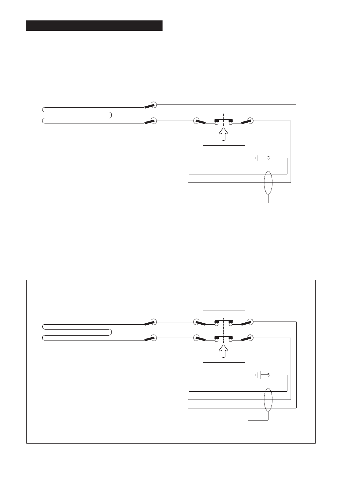
HTW-5 CIRCUIT DIAGRAM
Circuit Diagram for all markets excluding North America (single pole)
THERMAL SWITCH
CUT OUT REF 23
GREEN/YELLOW
BROWN
BLUE
SUPPLY LEAD
Circuit Diagram for North America only (double pole)
THERMAL SWITCH
CUT OUT REF 23
4
1
5
3
GREEN
BLACK
WHITE
7
SUPPLY LEAD
Page 11
DECLARATION OF CONFORMITY
This declaration identifies the product, manufacturer's name and address, and applicable specifications
recognised in the European community.
DECLARATION OF CONFORMITY
Manufacturer's Name: Hire Technicians Group Ltd.
Manufacturer's Address: Chalk Hill House
8 Chalk Hill
Watford
Herts WD1 4BH
declares that the product:
Product Name: Steam Team Steam Wallpaper Stripper
Model Name: HTW-5 230 Volt 50Hz Insulation Class 1
HTW-5 110 Volt 50Hz Insulation Class 1
conforms to the following:
Low Voltage Directive (Harmonised) 73/23/EU as amended
Electromagnetic Compatibility Directive 89/336/EU as amended
following the provisions of the directives:
89/392/EU, 93/44EU, 73/23/EU, 93/68/EU, 89/336/EU, 91/368/EU,
92/31/EU
harmonised standards applied:
EN60 335-1-88 (BS 3456-201 EN292-2-91
EN292-1-91 EN60 335-1-15
EN 50082-1-92 EN55014-93 (BS 800)
approvals held:
North America - CSA LR 65239
electrical safety test procedures comply with:
IEC 335 pt. 1-2, HD251 1-3 1982, BS 3456-201, CSA C22.2,
KEMA K78A1/W1 & W3, NEMKO 503./89, DIN VDE 0700 1/04.88
HD 264.S2 15/07.86, UL 561
Where the product is licensed to carry a National Approval Mark it is
certified that all such products comply with the terms of that license.
C.J. Hedger, Director of Engineering. 1 April 2012
8
Page 12
SERVICE & REPAIR
Name Address
Hiretech Pty Ltd Unit 2
62 Owen Street
Glendenning
NSW 2761
AUSTRALIA
Tel:
Fax:
Email:
Web:
+61 29625 9337
+61 29625 4770
[email protected]
www.hiretech.com.au
Abmast Inc
(Canada East)
6935 Rue Picard
Saint-Hyacinthe
QC
J2S 1H3
CANADA
Tel:
Fax:
Email:
Web:
(800) 361-0854
(800) 341 0554
asimar [email protected]
www.abmast.com
S T C as Praha Konevova 33
130 00 Praha 3
CZECH REPUBLIC
Tel:
Fax:
Email:
+ 4202 22585810
+42 02 22584421
[email protected]
Tool Matic A/S Vedskollevej
Herfolge
4681
DENMARK
Tel:
Fax:
Email:
Web:
+45 56250708
+45 56250705
[email protected]
www.tool-matic.dk
VIF Diff usion rue du Chateau-BP70112
59052 Roubaix
Cedex 1
FRANCE
Tel:
Fax:
Email:
+33 320 207880
+33 320 207889
[email protected]
Tucks Limited Hume Avenue
Park West Industrial Estate
Dublin 12
REP UBLIC OF IRELAND
Tel:
Fax:
Email:
Web:
+353 (01) 621 5555
+353 (01) 621 5563
[email protected]
www.tucks.ie
Turner Morris (Pty) Ltd 39 Robyn Road
Benrose
P.O. Box 27252
2011
SOUTH AFRICA
Tel:
Fax:
Email:
Web:
+27 11 618 4313
+27 11 618 2620
dbnsales@turner morris.co.z a
www.turnermorris.co.za
Hi r e Tec hni c i ans G roup Ltd Chalk Hill House
8 Chalk Hill
Watford
Herts
WD1 4BH
UNITED KINGDOM
Tel:
Fax:
Email:
Web:
+44 01923 252230
+44 01923 238799
[email protected]
www.hiretech.biz
Hir e te ch North Ame r ic a Inc PO Box 1564
Cliffotn Park
NY 12065
USA
Tel:
Fax:
Email:
Web:
+1 518 348 1300
(800) 563 2472
+1 518 348 1400
(800) 465 5981
[email protected]
www.hiretech.biz
Telephone, Facsimile, Email & Web
Contact your reseller for the name of your local service agent. Service and repairs undertaken by non-approved
service agents will void the product warranty. If you should have difficulty in obtaining service please contact your
distributor nearest to you at the address given below.
For the latestlist of Hiretech dealers check on the Hiretech web site at www.hiretech biz/contact/dealerlist.html.
9
Page 13

page left blank
10
Page 14

HIRETECH LIMITED WARRANTY
Hiretech warrants to the original purchaser that the Hiretech machine covered by this warranty is free from defects
in workmanship and materials. Should any part fail in the period of two years from the date of the original
purchase as a result of a defect, Hiretech will (at it’s option) either repair or replace the part without charge
provided that the machine has been operated in accordance withthe Owners Manual and Operating Instructions.
Should any such defect arise, please contact your nearest authorised repair agent. Standard service over land
mainland freight costs will be refunded on warranty repairs at the sole discretion of Hiretech or the authorised
repair agent. If the repair is non-warranty, the customer will be advised before any work is undertaken.
This warranty is the sole warranty by Hiretech and is in lieu of all other warranties express or implied and releases
Hiretech from all other obligations and liabilities.
This warranty does not apply to normal wear and tear to the machine, and in particular does not cover normal
wear parts such as mains cable, wheels, switches, relays, brushes, rubber parts, hoses and bearings. This
warranty also does not cover, and Hiretech will not be liable for, excessive wear caused by abnormal use.
Hiretech will under no circumstances be liable for alterations to the machine or for damage caused by third
persons, or for misuse or abuse of the machine, or damage caused during transportation. Repairs of the machine
made or attempted by persons other than those specifically authorised by Hiretech shall render this warranty void
and Hiretech will not be liable for such repairs, the cost of such repairs, or the consequences of such repairs.
Where spare parts are used on the machine and they do not conform to Hiretech specifications, this warranty will
be rendered void and Hiretech will not be liable.
Hiretech will not be liable for any indirect or consequential loss, damage, cost or expense of any kind whatever
and however caused whether arising under contract, tort (including negligence) or otherwise including (without
limitation) loss of production, loss of profits or contracts orof operating time or goodwill or anticipated savings.
Every effort has been made to present all information in this publication accurately, however no liability is
accepted for any inclusions or advice given or for omissions from this publication. Hiretech reserves the right to
make changes or improvements to its products without prior notice. Hiretech is a registered trademark of Hire
®
Technicians Group Ltd., all other trademarks are the property of their respective owners.
© Hire Technicians Group Ltd.
MANUFACTURED BY
HIRE TECHNICIANS GROUP LIMITED
CHALK HILL HOUSE, 8 CHALK HILL, WATFORD,
HERTS, WD19 4BH. UNITED KINGDOM
TEL: +44 (0)1923 332424 FAX: +44 (0)1923 332425
E-mail: [email protected] Web: www.hiretech.biz
 Loading...