

Page 1
Highly Reliable Systems
RAIDPac-II Operations Manual
1 Copyright © 2011 by Highly Reliable Systems. All rights reserved.
Documentation V1.1
Page 2

READ THIS FIRST
Important Quick Start Information for your High-Rely drive
● DO NOT ATTEMPT TO REMOVE RAIDPacs from their drive bays without fully depressing
the drive release lever. Forced removal of the drive will void your warranty and damaged the
units.
● The latest Service Packs are important! Microsoft has continued to Debug removable drives on
the Windows platforms. Make sure you have the latest service packs installed.
● Not all eSATA ports are created equal. And many hosts are finicky about working with third
party disk controllers. We offer eSATA controllers tested to work with our systems but can not
guarantee those cards will work properly in your host computer. If you have difficulties getting
your host controller card to work, see the Read First page on our website under tech support or
directly at:
https://www.high-rely.com/HR3/includes/SupportReadFirst.php
Other eSATA ports may only recognize the first drive in a multi-drive system or may not
function at all. Host controller ESATA Ports should support hot-Swap and “port multiplier”
capabilities.
● For USB 3.0 connections, be sure to have the absolute LATEST drivers for your USB 3.0 host
controller.
● If you are using multiple RAIDPacs in a single bay RAIDFrame, you may have a drive letter
problem as you change your media. Windows will assign drive letters based on the next
available letter and sometimes in a manner that appears random, which could cause your
backup software to fail depending on how it is configured. You can use the High-Rely Drive
Manager utility HRDM2.MSI to solve this problem. To do this, install HRDM2 on the
machine that the High-Rely system will be connected to.
● Particular photos in this manual may not be your exact unit.
2 Copyright © 2011 by Highly Reliable Systems. All rights reserved.
Page 3

Table of Contents
1.Introduction.......................................................................................................................................4
2.Front Face features............................................................................................................................5
3.Rear Features.....................................................................................................................................6
4.Side Features.....................................................................................................................................7
5.Installation and Use...........................................................................................................................7
6.Status And Indicators.........................................................................................................................8
7.Changing RAID configuration..........................................................................................................9
7.1.Using Jumpers to change your RAID settings............................................................................9
8.Using HW RAID Manager..............................................................................................................13
8.1.Monitoring your RAIDPacs with HW RAID manager.............................................................14
9.Troubleshooting and Maintenance..................................................................................................16
9.1.RP2 Service Access..................................................................................................................17
9.2.Changing failed drives..............................................................................................................17
9.3.Changing failed fan...................................................................................................................18
9.4.Installing new drives.................................................................................................................19
10.Emergency (Field) Access to RP2 data from outside of a RAIDFrame........................................19
3 Copyright © 2011 by Highly Reliable Systems. All rights reserved.
Page 4

1. Introduction
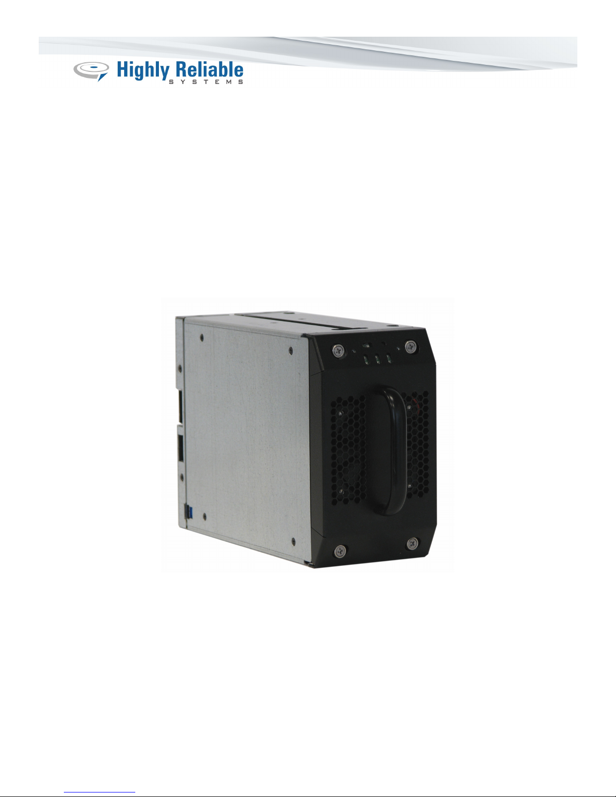
High-Rely's new RAIDPac-II (RP2) is a completely self-contained, hot-pluggable RAIDed drive
system. It includes its own RAID controller, cooling system and up to 3) 3.5” hard drives. It is
designed to be used inside RAIDFrame devices but can also be accessed stand-alone via either SATA or
USB 3.0 and a standard Molex drive power connector with adequate power.
The RP2 is compatible with all existing RAIDFrame units and can co-exist with older RAIDPacs in the
same unit simultaneously. This manual is dedicated to the features of the RP2 and operational notes.
The previous version of RAIDPac is covered in the manual for each particular RAIDFrame unit.
4 Copyright © 2011 by Highly Reliable Systems. All rights reserved.
Page 5
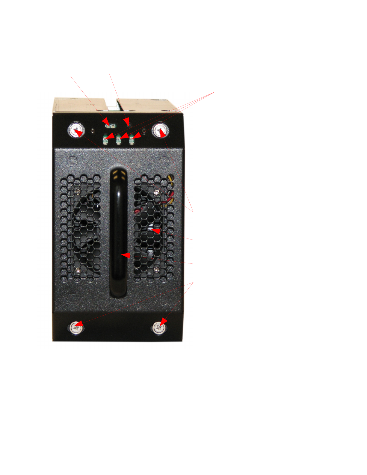
2. Front Face features
RAID Activity/Status
Indicator
Error Reset Button
Drive Activity/Status Indicators
for RAIDPacII internal bays
1,2 and 3.
Spring-out Retained
Screws for service
access.
Cooling Fan
Pull/Carry Handle
Spring-out Retained
Screws for service
access.
Figure 1 - RP2 front face features.
5 Copyright © 2011 by Highly Reliable Systems. All rights reserved.
Page 6
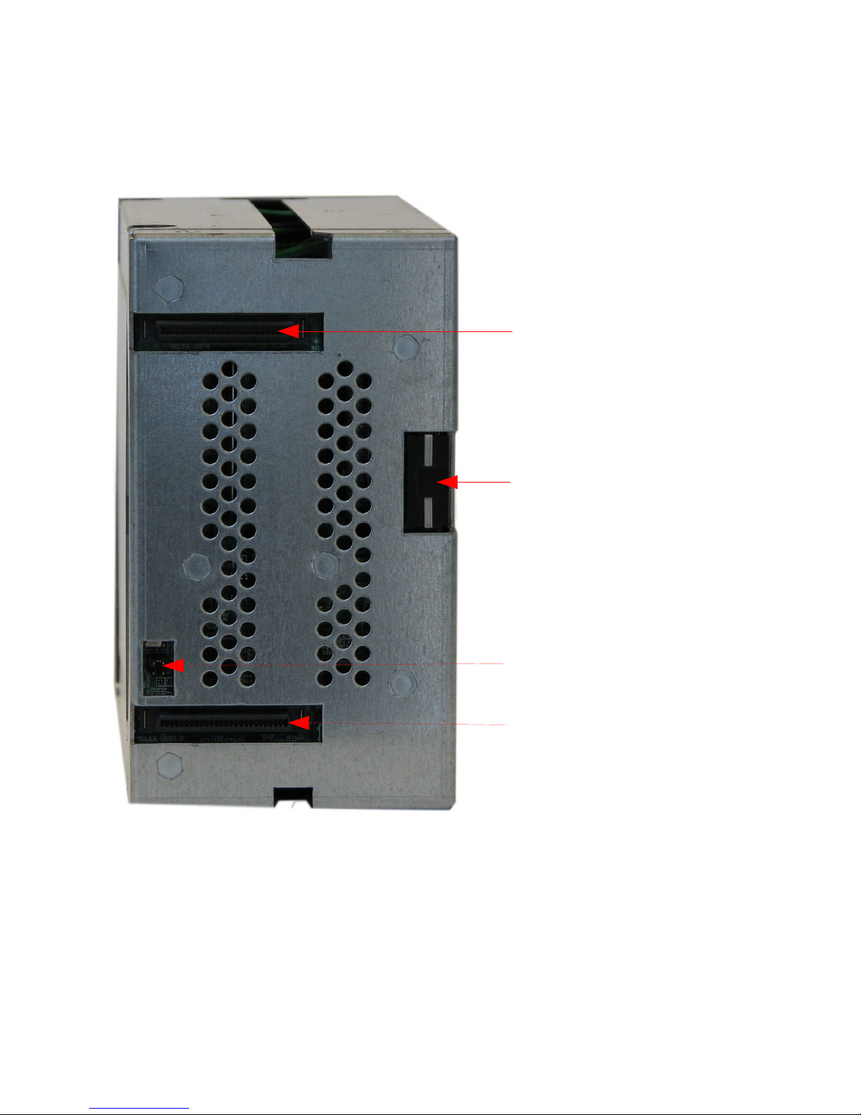
3. Rear Features
SATA Docking connector
MOLEX drive power
connector (for field use).
RAID type selection
jumpers.
USB 3.0 Docking connector (for
future use).
Figure 2 - RP2 Rear side features.
6 Copyright © 2011 by Highly Reliable Systems. All rights reserved.
Page 7
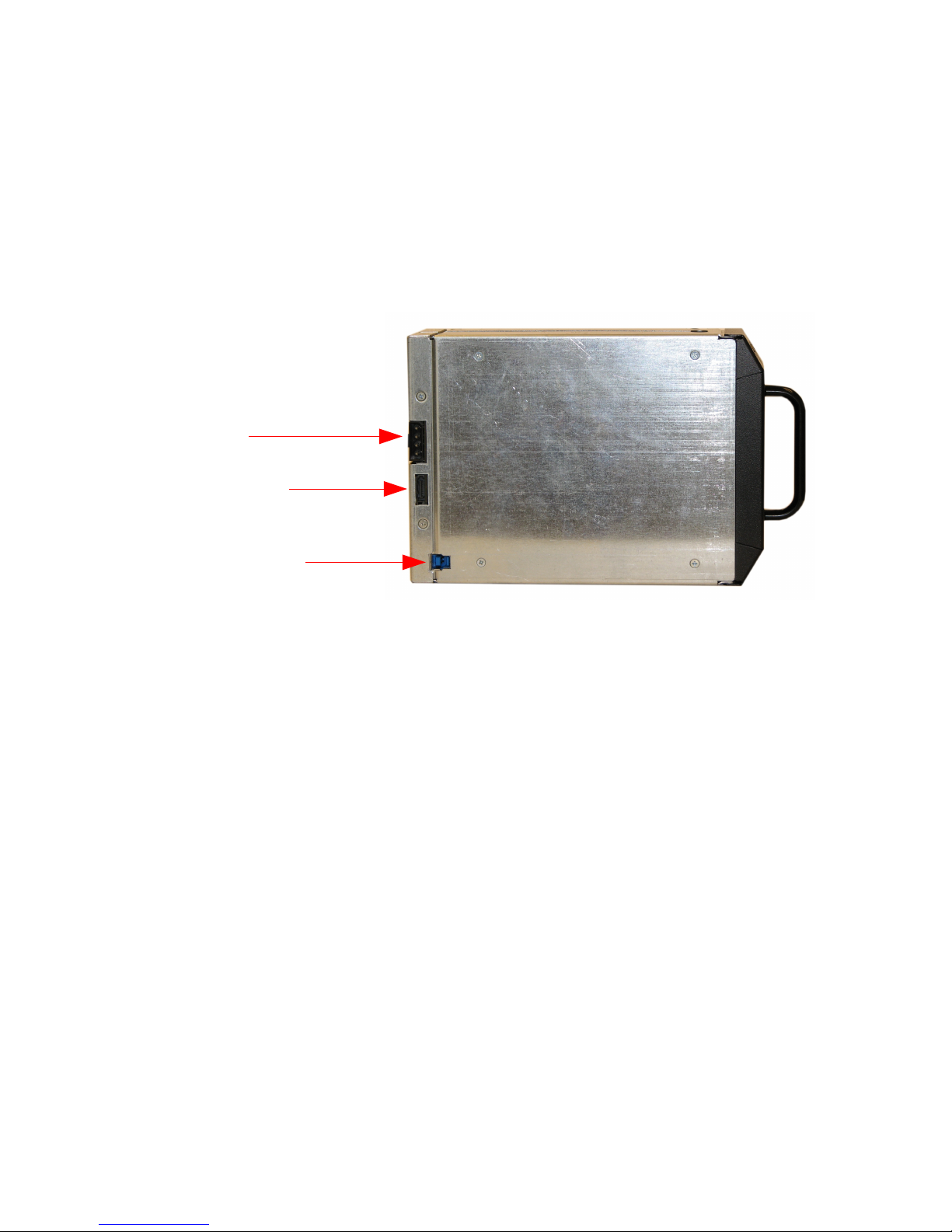
4. Side Features
Standard MOLEX
Hard Drive Power
Connector
ISATA connector
USB 3.0 connector
Figure 3 - RP2 Side features.
5. Installation and Use
Like the previous version of RAIDPac (RP1), RP2's are already in a RAID configuration and formatted
from the factory. By inserting the unit into your RAIDFrame, within 2 minutes you should see the
volume appear on-line.
You may need to reformat the drive for your operating system's needs or your configuration. But no
further processes or configurations should be necessary unless you need to change the configuration
from the way it was ordered. Please note that most drives with useable capacities in excess of 2 TB
will be partitioned as GPT. Some older operating systems may not recognize a GPT (GUID Partition
Table) partition.
7 Copyright © 2011 by Highly Reliable Systems. All rights reserved.
Page 8
6. Status And Indicators
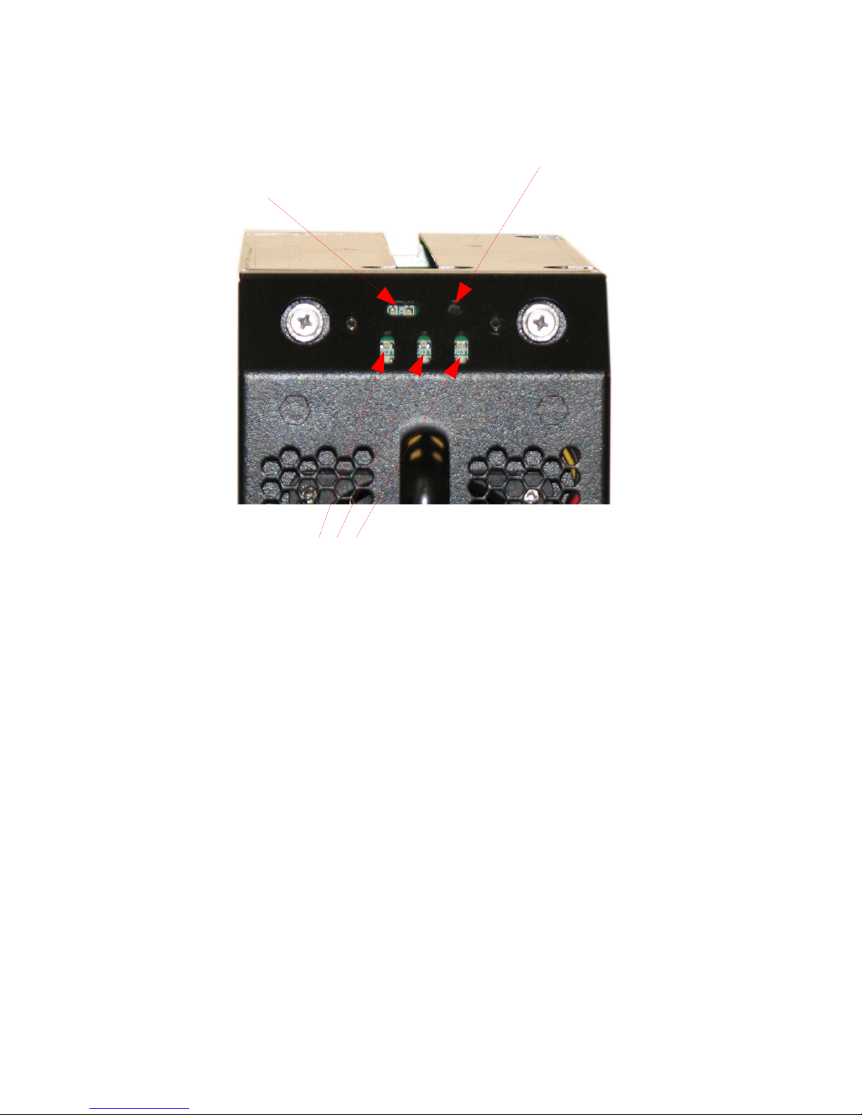
RAID Status:
-Green: online working.
-Red: offline/error or degraded.
Mute/Silence Alarm – use
pen.
Audible Alarm conditions:
-Drive(s) fail.
-RAID fail.
-Over temperature.
Drive Status (Disks 1, 2, 3):
-Blue: Online
-Blue Blinking: Online with activity
-Red: Offline/Error.
-Red/Blue Blinking: Rebuilding.
Figure 4 - Indicators Status
The RP2's visual and audible indicators will alert you to trouble. The drive status indicators
immediately indicate proper, improper or compromised operations. A properly running RP2 will be
silent (no alarm tone), have a green light at the top and a blue light for each functioning drive installed
in the RP2.
Should a drive fail, the audible alarm will sound, a red light will light corresponding to the drive
position which failed.
Should should the failure be severe enough to break the RAID, the green light at the top will be red, the
unit will go off-line and there maybe red lights also on the drive(s) which are not operating properly.
See the section below on troubleshooting for more information.
8 Copyright © 2011 by Highly Reliable Systems. All rights reserved.
Page 9

7. Changing RAID configuration
The RP2 supports several RAID configurations. Those configurations are set at the factory but can
easily be changed again in the field by two methods. One method is to use the jumpers on the back of
the RP2 itself. The other is to use a free windows program called HW RAID Manager (available for
download from our website). Using the jumper method allows quick change without running the
program and maybe the only way in installations which a windows machine is not connected to the
RAIDFrame.
7.1. Using Jumpers to change your RAID settings
On the back of the RP2 is a small cutout with two .100" standard center pin jumpers. Each time the
RP2 is inserted, it checks to see if these jumpers have changed from the last time. If they have, it
erases the current configuration and sets up the new configuration. WARNING! CHANGING THESE
JUMPERS WILL CAUSE COMPLETE DATA LOSS! Only move them if loosing your data is
acceptable.
Once a RAID type has been set, that type is branded onto the hard drives. Even though the jumpers
may change thereafter, the RAID type will not change while a branded drive set is in the RP2. RAID
type branding has priority over the jumpers. However, should the jumpers be set to the Single Drive
setting, the branding is removed and the next RAID type change will become the new branding.
For example, if you had 3 1TB drives in a RAID 5 configuration that you wished to change to RAID 0,
you would first put the jumpers in the Single Drive setting (remove them both). Then install the RP2
and let it power up. Once you hear the beep, it will have cleared the RAID branding from the drives
and only a single drive's capacity will be shown to the system. Then, remove the RP2, set the jumpers
to the RAID 0 setting. Insert the RP2 again. When you hear the beep again, it will have reconfigured
itself to the RAID 0 setting. Any changes to the jumpers after this will have no effect on this drive set
until it is placed in the Single Drive setting again.
See Figure 5 and 6 below for different RAID settings.
9 Copyright © 2011 by Highly Reliable Systems. All rights reserved.
Page 10
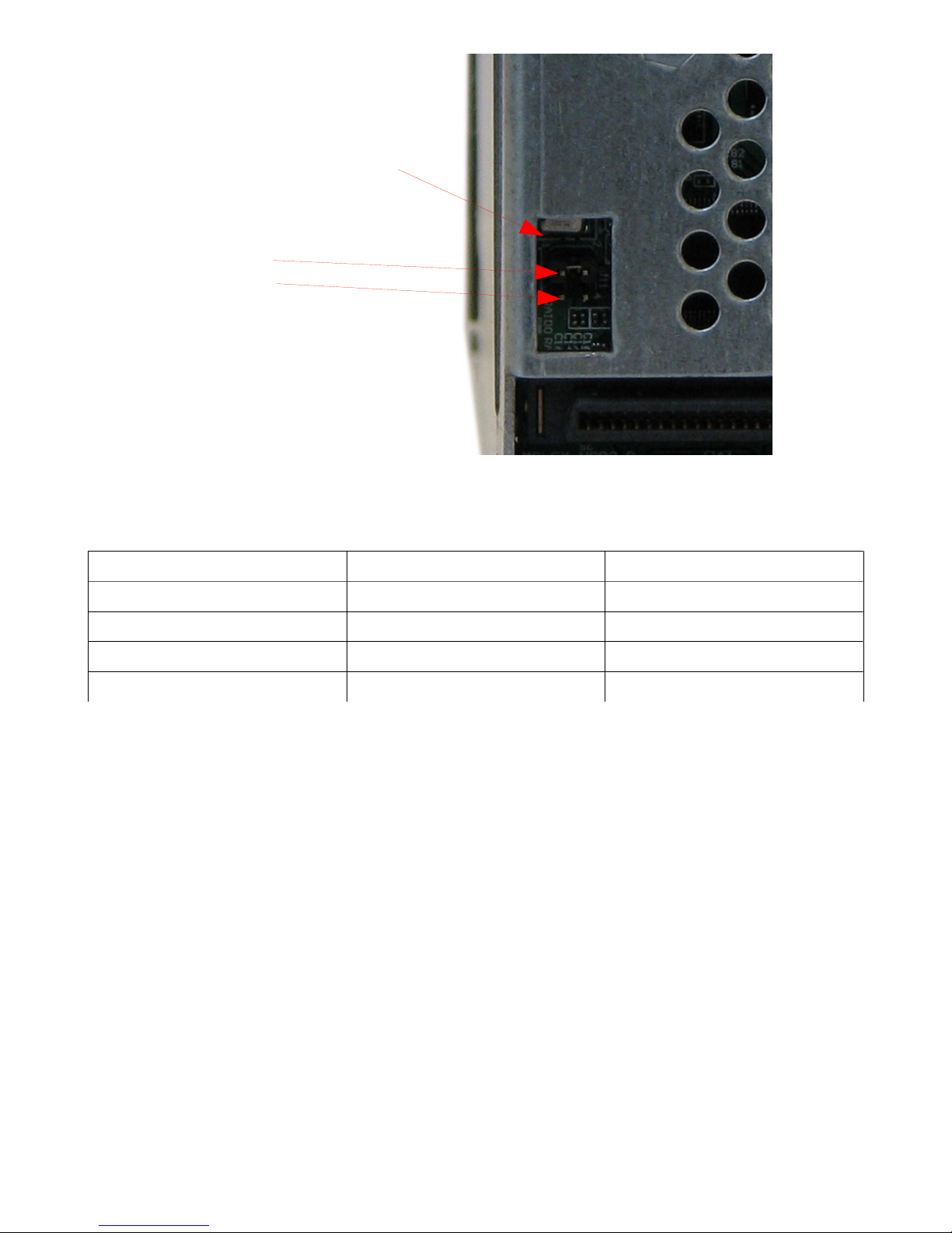
RAID Type selection
jumpers:
Position 1
Position 2
Figure 5 - RAID setting jumper pins.
RAID Type Jumper Position 1 Jumper Position 2
RAID 0 Open (Off) Covered (On)
RAID 1 Covered (On) Open (Off)
RAID 5 Covered (On) Covered (On)
Single Drive (Clear Branding) Open (Off) Open (Off)
10 Copyright © 2011 by Highly Reliable Systems. All rights reserved.
Page 11

RAID Type (*= settable in HW Manager only, may not
apply to use in RP2)
Description
0 RAID 0: Striped, is the segmentation of logically
sequential data, such as a single file, so that
segments can be assigned to multiple hard disks in
a round-robin fashion and thus written
concurrently.
The advantages of RAID 0 are that it achieves
higher performance and capacity by accumulating
each individual hard disks performance and
capacity. However, if any one hard disk becomes
defective, information stored in the entire RAID0
array will be invalid!
The RAID group controller will make use of the
same smallest size disk space in each hard disk
under RAID 0 condition. For example, if a RAID
0 consists of 5 different size hard disks, the total
size of usable space of this RAID0 will be (the
capacity of smallest size hard disk) X (the number
of hard disks in this RAID0).
1 RAID 1 : Mirror, is the replication of data onto
separate hard disks in real time to ensure
continuous availability. In a RAID 1 system with
two hard disks, data in a hard disk will be exactly
the same as the data in the other hard disk.
The RAID group controller will also make use of
same smallest size disk space in each hard disk of
RAID 1. That is, the RAID group controller
controller will write data to the same disk space in
each hard disk. When reading data, RAID group
controller will read data from a favored hard disk.
Failure in a hard disk will cause the RAID group
controller to enter a degraded mode. The host
controller still could read/write data normally
without knowing any difference. Once the
defective drive is replaced, the RAID group
controller will then enter auto-rebuild mode
automatically. If there is only some partial defect
in a hard disk, the RAID group controller will
read data from the other healthy hard drive.
*10 RAID 10 (1+0 - mirrored and striped) two
11 Copyright © 2011 by Highly Reliable Systems. All rights reserved.
Page 12

mirrored sets in one striped set (minimum four
disks; even number of disks) provides fault
tolerance and improved performance but increases
complexity. RAID 1+0 creates a striped set from a
series of mirrored drives. The array can sustain
multiple drive losses so long as no mirror loses all
its drives. With 4 drives, this means that any one
drive can fail. But if two drives fail, the whole
RAID will break unless those two drives happen
to be in the same mirror. RAID 10 offers better
protection than RAID 5, 3 or RAID 1 because
there is the added possibility of survival if two
drives fail (under the right combination).
*3 RAID 3 (byte-level striping with dedicated
parity), data is striped such that each sequential
byte is on a different disk. Parity is calculated
across corresponding bytes on disks and stored on
a dedicated parity disk. Higher data transfer rates
are possible. A single drive failure is tolerated.
RAID group controller will rebuild the failed
drive upon replacement automatically.
5 RAID 5 (block-level striping with distributed
parity) distributes parity along with the data and
requires all drives but one to be present to operate;
drive failure requires replacement, but the array is
not destroyed by a single drive failure. Upon drive
failure, any subsequent reads can be calculated
from the distributed parity such that the drive
failure is masked from the end user. The array will
have data loss in the event of a second drive
failure and is vulnerable until the data that was on
the failed drive is rebuilt onto a replacement drive.
*LARGE LARGE: The designated drives are concatenated
into a single large volume. The difference
between LARGE and RAID0 is that RAID 0
offers better performance but at the cost of
flexibility. LARGE can concatenate drives of
different sizes and use the complete space of all
drives. HOWVER, LIKE RAID 0, LARGE CAN
BECOME UNUSABLE IF JUST A SINGLE
DRIVE FAILS.
*CLONE Clone: The designated drives are mirror copies of
each other.
12 Copyright © 2011 by Highly Reliable Systems. All rights reserved.
Page 13
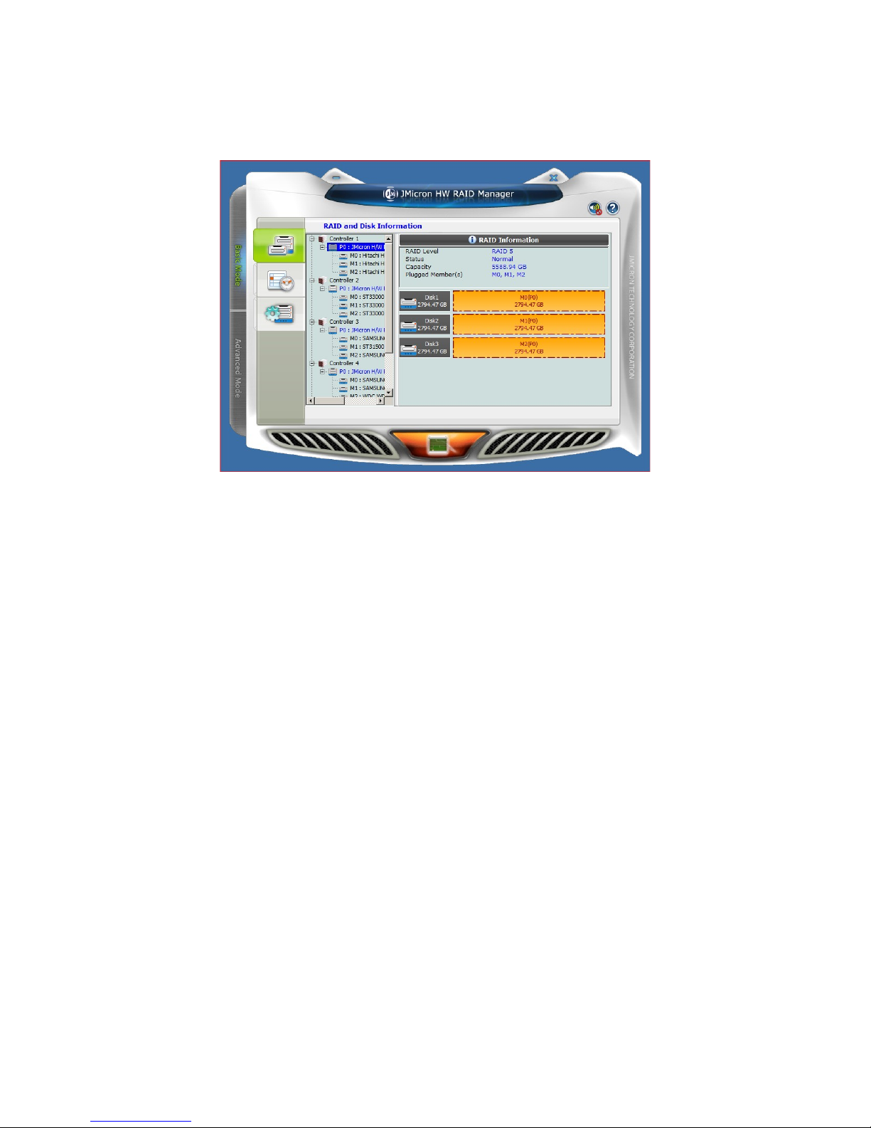
Figure 6 - RAID Type Descriptions
8. Using HW RAID Manager
Figure 7 – HW RAID Manager Screen. RAID Information
*This section is not intended to fully cover the features of the JMicron HW RAID Manager, as this is
not High-Rely's software, but rather software from the chip set maker of the chip set used in the RP2.
So, we will cover some basics. But, since this software is not under the control of High-Rely, it is
subject to change without notice. As of this writing, the version of software was 0.09.69 (check by
clicking the (?) in the top right corner).
The HW RAID Manager program is a Windows only program. The HW RAID manager program will
allow you to see RP2's internal drives, change RAID configurations, check the event log, and set up
SMTP alerts for the error conditions you select for the various RAIDPacs. If a drive RP2 is rebuilding,
it can tell you the percentage of completion of the rebuild. You can also change the RAID rebuild
priority.
On the left hand side of the panel are two tabs, "Basic Mode" and "Advanced Mode" Clicking in these
will allow you to use the corresponding feature sets.
At this time, the HW RAID Manager runs only in the tray for Windows XP and Server 2003. For
Windows Vista, 7 and Server 2008 and Server 2008 R 2, it runs as a service (JMRAID Manager). This
can cause problems for XP and Server 2003 users as it will not be present to log events or email
messages of events unless the user HW RAID Manager was installed for is logged in.
There are other software utilities, tools and ways to make a program run as a service. Google the
phrase, "running a program as a service" for a list of methods which may work.
13 Copyright © 2011 by Highly Reliable Systems. All rights reserved.
Page 14
8.1. Monitoring your RAIDPacs with HW RAID manager.
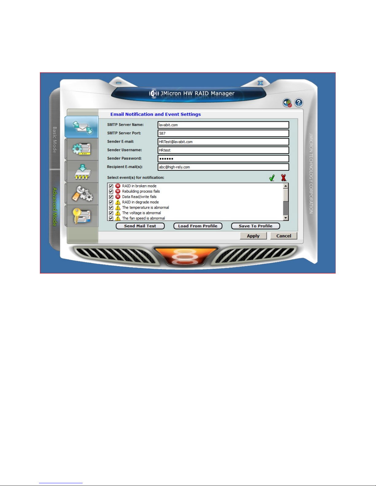
HW Manager can send you SMTP messages for certain events that you flag. In the JM Manager
Interface, click the Advanced Tab on the left, click the arrow/envelope icon at the top of the next tab set
to get to the screen shown below.
Figure 8 – HW RAID Manager. Email Notification and Event Settings.
As you can see, you can select a wide variety of events to receive notifications for.
This is a simple SMTP email interface. Some users may have troubles with their email servers and
SMTP without encryption. HW Manager does not currently support SSL or TLS encryption used in
many newer emails servers. High-rely does not support this program nor troubleshoot email problems.
If you're having difficulty, contact your service tech or try the suggestions below:
-Google for and download the program, SendEMail.exe.
-Use SendEMail.exe to perform this simple test:
-From the command prompt where you downloaded SendEMail.exe type:
sendEmail -f <Your Email> -t <Recipient's email> -s <Your Server's URL>:<Your Eserver's port> -xu
<Your User Name> -xp <Your Password> -u "This is a test email" -m "Hi buddy, this is a test
email. "
Here is an example using Lavabit.com:
sendEmail -f [email protected] -t [email protected] -s lavabit.com:587 -xu HRtest -xp HRtest -u
"This is a test email" -m "Hi buddy, this is a test email. "
14 Copyright © 2011 by Highly Reliable Systems. All rights reserved.
Page 15

If this test works, your email server should work with HW RAID Manager. But if not, you may need to
reconfigure your email server, routers or use an external server like Lavabit.
Here are some example settings in HW RAID manager using Lavabit.com:
SMTP Server Name: LAVABIT.COM
SMTP Server Port: 587
Sender Email: [email protected]
Sender Username: HRtest
Sender Passweord: HRtest
Recipient's Email: <your email address>
Then click Send Mail Test. And you see the test message appear in a few minutes.
Note: Port 587 is an alternate for port 25 which is often blocked in today's business routers.
We suggest you also try various target email addresses in case lavabit.com is blocked.
If this works for you but you can not configure your email server or firewalls to work, go to
lavabit.com and set up your own account. Currently at the time of this writing, the accounts are free
and simple to setup.
15 Copyright © 2011 by Highly Reliable Systems. All rights reserved.
Page 16
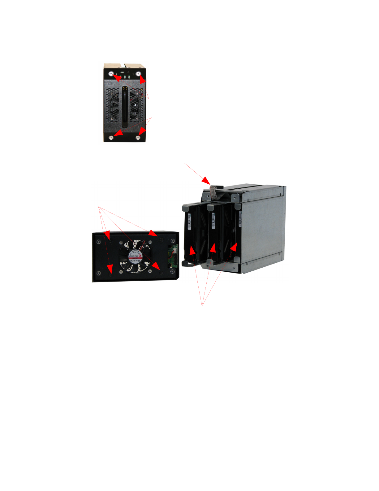
9. Troubleshooting and Maintenance
(4) Spring-out retained #2
phillips screws.
Front Panel connector
ribbon cable.
Back side of RP2's front
panel. For fan service
access, remove these four
#2 phillips screws.
Figure 9 - RP2's Service Access
RP2's serviceable parts can all be accessed and changed from the front panel of the device, EVEN
WHILE IN A RAIDFRAME BAY AND STILL RUNNING! The internal drives, fan and panel can all
actually be safely "hot-plugged" within the RP2 if the pack is running a mission critical function.
16 Copyright © 2011 by Highly Reliable Systems. All rights reserved.
3) 3.5“ SATA Hard Drives
mounted on RP2 rails (slide
out).
Page 17

9.1. RP2 Service Access
WARNINGS ABOUT REMOVING PANEL:
• If pulling the front panel while the unit is a chassis and running, do not leave the panel off for
an extended period of time. There is very little cooling once the fan is out of position and the
unit may overheat.
• The sheet metal around the ribbon cable is sharp, be careful to not cut the cable or wedge it
between any of the edges.
Be careful when reassembling to not let the ribbon cable stick out into the guide track and locking hole
on the top of the chassis.
To access the fan and hard drives area for service:
1. Loosen the four spring-out retained screws until they "pop-out" with a #2 Phillips screwdriver.
2. Pull the panel off by grasping the handle and pulling gently. There is a ribbon cable attached to
the top of the panel so be careful to not pull the panel out more than 2" from the rest of the
chassis. If necessary, you can unplug the front panel from the cable, EVEN WHILE THE UNIT
IS POWERED ON AND RUNNING if necessary. Note the direction of the cable, it is keyed
and should only fit properly in one direction.
9.2. Changing failed drives.
If a drive is erroring on an RP2, before attempting to change the drive, try removing the RP2 from the
chassis, wait 30 seconds, and install it again. If the error goes away and the drive starts to rebuild,
things are probably fine as the drive itself just needed a power reset. However, if the error persists,
then replacement of the drive in error is probably necessary. The position of the red light indicating the
error, corresponds to the position of the physical drive.
To change the failed drive, first, follow the RP2 Service Access procedure above. Then:
1. To remove the defective drive from the RP2 chassis, hold the chassis firm (if not installed in a
RAIDFrame bay). Pull straight out on the front edges of the slide rails for the drive you wish to
change. The drive maybe firm at first but should slide out once you overcome the drive
connector's holding force.
2. Unscrew the drive mounting rails from the defective drive and install them in same direction
and orientation of the new drive.
3. Re-insert the new drive back into the RP2 chassis all the way.
4. Re-install the ribbon cable on the front panel if it was disconnected.
5. Re-install the front panel.
6. Once the RP2 is powered on (or if it was powered on during the whole process), it will begin to
rebuild automatically if there were no further problems. It will also set the audible alarm
indicating the rebuild. Press the mute button on the front to stop the tone.
17 Copyright © 2011 by Highly Reliable Systems. All rights reserved.
Page 18

WARNINGS ABOUT REMOVING PANEL:
• If pulling the front panel while the unit is a chassis and running, do not leave the panel off for
an extended period of time. There is very little cooling once the fan is out of position and the
unit may overheat.
• The sheet metal around the ribbon cable is sharp, be careful to not cut the cable or wedge it
between any of the edges.
• Be careful when reassembling to not let the ribbon cable stick out into the guide track and
locking hole on the top of the chassis.
9.3. Changing failed fan.
In the event the RP2's fan fails, the unit maybe fine and operate indefinitely provided the secondary
cooling fans in the RAIDFrame chassis is able to keep the unit cool enough. Since the RP2's fan sit
right up front in the RP2's front panel, checking if a fan is running is an easy audible or visual
inspection.
If you received messages via HW RAID manager of temperature problems, the RP2's fan is the first
suspect. If the fan is indeed stopped or sluggish, or making noises like the bearing is failing, the
replacement procedure is simple and can even be done while the pack is running in a RAIDFrame
chassis without interruption.
Follow the RP2's Service Access procedure above. Then:
1. Remove the four addition inner screws shown above that are located on the inside back of the
RP2 front panel.
2. Note the air flow direction: it draws air from outside and blows it inward. Also note the
position of the fan cable.
3. Remove the four fan screws on the fan mount plate.
4. Unplug the fan connector from the indicator board mounted on the RP2 front panel.
5. Install the replacement fan in the same airflow direction and with the fan cable orientation.
6. Plug the fan cable back in.
7. Install the fan plate.
8. Install the RP2 front panel in the reverse fashion described in the above Service Access
procedure.
18 Copyright © 2011 by Highly Reliable Systems. All rights reserved.
Page 19

9.4. Installing new drives.
Should the desire ever come to install a complete set of newer and/or larger drives, the procedure is
simple.
1. Follow the steps outline above in the section above for changing a failed drive. Except, do this
for all three drives then re-assemble the RP2.
2. Install the RP2 in a RAIDFrame.
3. Follow the procedure above for changing your RAID configuration to establish the RAID.
4. Initialize and format the new volume in your operating system. If you're using HRDM2, you
need to re-register the new volume with HRDM2.
10. Emergency (Field) Access to RP2 data from outside of a
RAIDFrame.
One of the great capabilities of the RP2 is the ability for you to access your volume in the field and
without a RAIDFrame bay. Original RAIDPacs supported this as well but some dis-assembly was
required and only an iSATA connection was available.
The RP2 requires no dis-assembly. It provides both a SATA connection as well as USB 3.0 (works
with USB 2.0 also). And, a standard hard drive MOLEX power plug allows you to plug it into almost
any standard PC power supply. WARNING! It will usually work to power the RP2 from the same
computer as the computer you're plugging it into is using. However, that power supply may not be
rated to power the computer and your RP2, DAMAGE to your power supply could occur.
Because the RP2 contains its own RAID controller which presents the whole RAID to the host as a
single volume, no special driver is needed. It's just a HUGE USB 3.0 thumb drive (for a giant's thumb)
but it needs the external supply voltage from a computer type of power supply.
An iSATA port is also available to connect the unit with if USB 3.0 or USB 2.0 are not practical.
Because iSATA can be more tricky to connect, we suggest trying USB 3.0 first. Only one or the other
maybe connected.
For the safest possible connection. Power off the computer and power supply. Make the connections
you need to the RP2. Then power everything on. Hot plugging the field connections on the RP2 is not
recommended.
19 Copyright © 2011 by Highly Reliable Systems. All rights reserved.
Page 20

Contact Information
Highly Reliable Systems
1900 Vassar Street
Reno Nevada 89502-2109
TEL: 775-329-5139
FAX: 775-322-5397
www.high-rely.com
20 Copyright © 2011 by Highly Reliable Systems. All rights reserved.
 Loading...