

Page 1
HTI
_CW
CW
5
HIGH
TECHNOLOGY
IN
REFRIGERATION
DEVICES
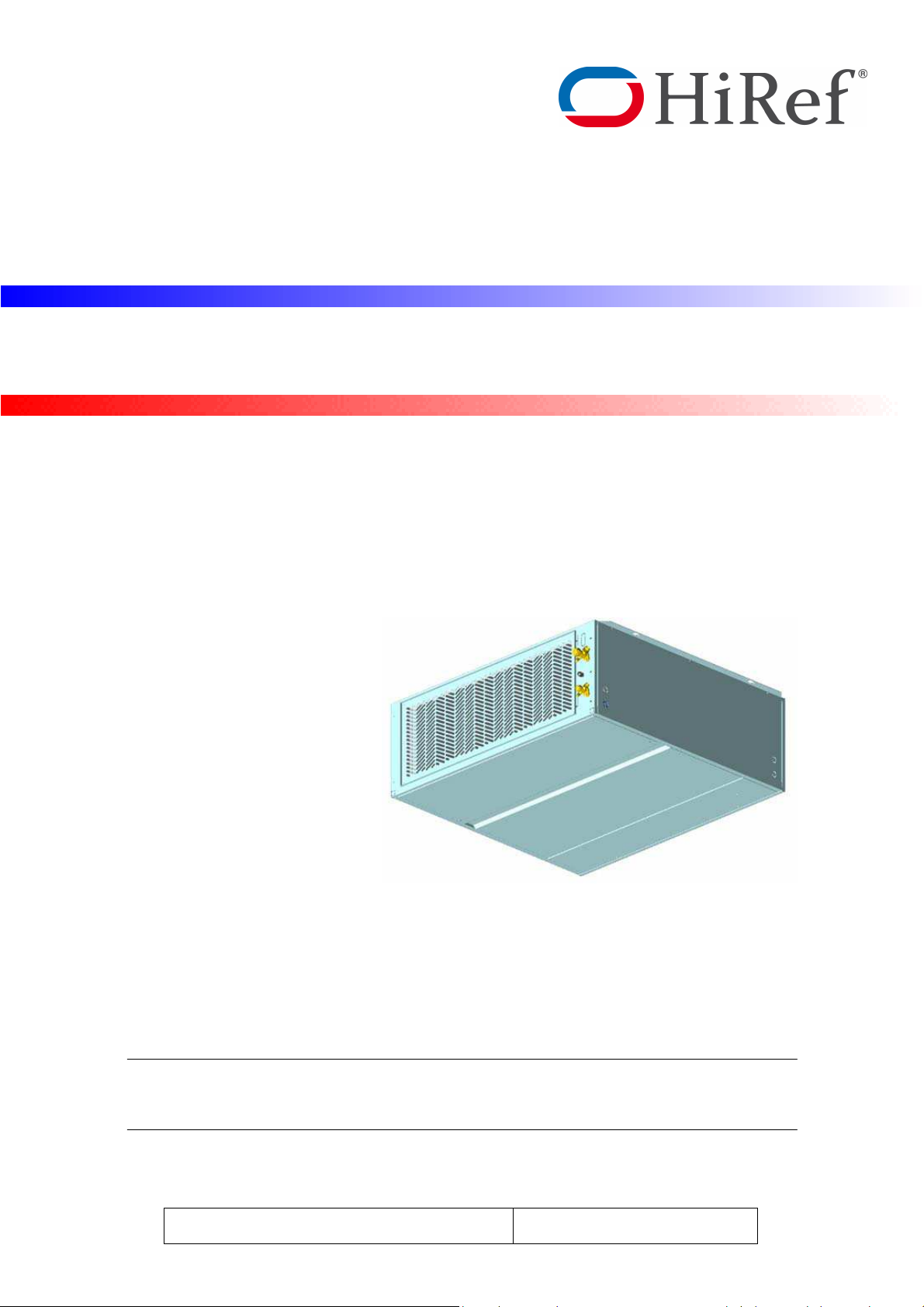
H T I - CW
Packaged Air Conditioning Unit
Chilled water unit
Users Manual
HF61G00269SB HTI-0-UM-GB_
GB
Rev. 20-05-201
Page 2

HIGH TECHNOLOGY IN REFRIGERATION DEVICES
2
HF61G00269SB HTI-0-UM-GB_CW
Page 3

3
HIGH TECHNOLOGY IN REFRIGERATION DEVICES
Index
1 General Description.................................................................................................................. 4
1.1 Structure ...........................................................................................................................................4
1.2 Field of application ...........................................................................................................................4
1.3 Cooling circuit ...................................................................................................................................4
1.4 Hydraulic section ..............................................................................................................................6
1.5 Installation warnings .........................................................................................................................7
2 Inspection / Transport .............................................................................................................. 8
2.1 Inspection on receipt ........................................................................................................................8
2.2 Lifting and transport .........................................................................................................................8
2.3 Unpacking ........................................................................................................................................8
3 Installation ................................................................................................................................ 9
3.1 HTI - Indoor unit positioning .............................................................................................................9
3.2 Free-cooling duct connections (optional) ......................................................................................... 10
4 Electrical Connections ........................................................................................................... 11
4.1 Generalities ................................................................................................................................... 11
4.2 Starting up for the first time ........................................................................................................... 12
4.3 Starting operation .......................................................................................................................... 12
5 Operating Parameters Setting ............................................................................................... 12
5.1 Generalities ................................................................................................................................... 12
6 Maintenance ............................................................................................................................ 13
6.1 Warnings ....................................................................................................................................... 13
6.2 Periodical checks .......................................................................................................................... 13
7 Troubleshooting ..................................................................................................................... 15
HF61G00269SA HTI-0-UM-GB_CW
Page 4
HIGH TECHNOLOGY IN REFRIGERATION DEVICES
1 General Description
HTS “HiRef Telecom Split” units composed by an evaporating indoor unit HTI for ceiling or wall installation, mainly
for electronic equipped shelters, process centers, telecommunications sites from 4.5 to 38 kW of nominal cooling
capacity.
The system provides air filtration, indoor ventilation, cooling, heating, free cooling with outdoor fresh air to assure
the useful climate in the site.
1.1 Structure
All HTS units have a galvanized sheet steel supporting base and enclosing panels are painted with epoxy polyester
powder coating cured at 180°C, or, on request, painted galvanized sheet steel (RALxxxx).
1.2 Field of application
All HTS units are to be used within the operating limits stated in this manual (see Tab. 1); failure to comply with said
limits will invalidate the warranties provided in the contract of sale.
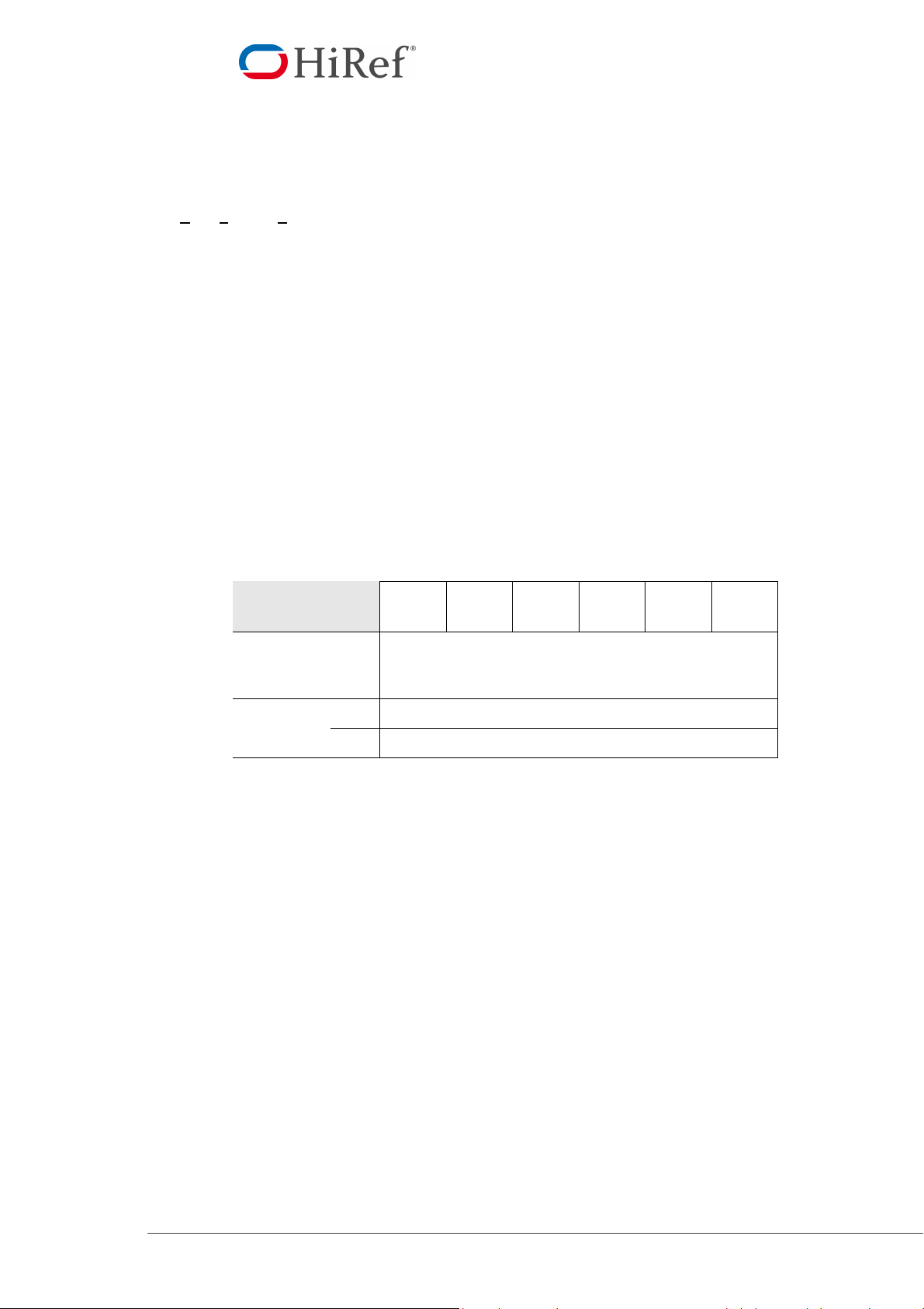
Tab. 1 Operating limits
Model: HTI
073
105
120
145
310
380
Power supply
400Vac ±10% / 3Ph+N+PE / 50Hz
Storage
conditions
Min
Max
-10 °C / 90% R.H.
55 °C / 90% R.H.
1.3 Cooling circuit
The entire cooling circuit is built in the HiRef factory using only components of the finest quality brands and
processes conforming to the specifications of “Directive 97/23” for brazing and testing.
Cooling components
• Water valves
• Airflow switch
• Filter
Electric control board
The electric control board is constructed and wired in accordance with Directives 73/23/EEC and 89/336/EEC and
related standards. All the remote controls use 24V signals powered by an insulating transformer.
Note: The mechanical safety devices such as the high pressure switch are of the kind that trigger directly; their
efficiency will not be affected by any faults occurring in the microprocessor control circuit, in compliance with
97/23 PED.
Microprocessor control
The microprocessor built into the unit allows the different operating parameters to be controlled from a set of
pushbuttons situated on the electric control board:
• Alarm management: -
- Dirty filters alarm;
- Air flow alarm.
4
HF61G00269SB HTI-0-UM-GB_CW
Page 5
5
HIGH TECHNOLOGY IN REFRIGERATION DEVICES
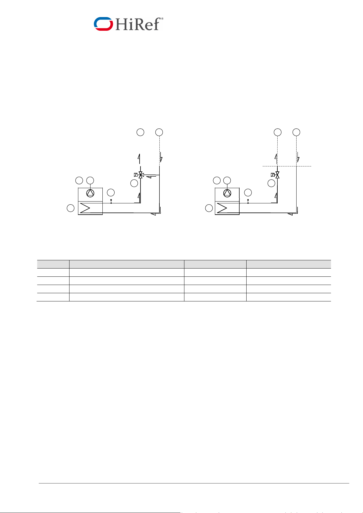
3 –
way valve
2-way valve
• Alarm signalling.
• Display of operating parameters.
• RS232, RS485 serial output management (optional).
• Phase sequence error (Not displayed by the mP, but prevents the compressor from starting up).
See microprocessor control manual for further details, also in relation to particular customer
specifications.
Fig. 1 Basic cooling circuits DX
2
1
2 1
5
M
4 M4
6
3
5
7
6
Pos Description Pos. Description
1 Chilled water inlet 5 Coil heat exchanger
2 Chilled water outlet 6 Breather valve
3 3-way valve 7 2-way valve (Opt.)
4 Plug fan
-
HF61G00269SA HTI-0-UM-GB_CW
Page 6

HIGH TECHNOLOGY IN REFRIGERATION DEVICES
1.4 Hydraulic section
Three-way valve
The 3-way valve used on HTI0105 version unit for inlet water flow regulation allowing a foundamentally maximum
precision’s regulation on CCAC applications.
Tab. 3 Technical characteristics
HTI 0073-0105
Kvs valve (m3/h)
PN valve
P max. (kPa)
Connections (inch)
6.3 6.3 16,0
200 200 200
3/4” 3/4” 1 1/4”
16 16 16
120-145 310-380
Air presence in hydraulic circuit
It is necessary to leak air from the hydraulic circuit of unit after the connection to the external circuit. To do this,
open the below panel to valve access and use adapted tools for the manual valve’s setting.
6
HF61G00269SB HTI-0-UM-GB_CW
Page 7

7
HIGH TECHNOLOGY IN REFRIGERATION DEVICES
1.5 Installation warnings
General rules
• When installing or servicing the unit, you must strictly follow the rules provided in this manual, comply with
the directions on the units themselves and take all such precautions as are necessary.
• The fluids under pressure in the cooling circuit and the presence of electrical components may cause
hazardous situations during installation and maintenance work.
All work on the unit must be carried out by qualified personnel only, trained to do their job
in accordance with current laws and regulations.
• Failure to comply with the rules provided in this manual or any modification made to the unit without prior
authorisation will result in the immediate invalidation of the warranty.
Warning: Before performing any kind of work on the unit, make sure it has been
disconnected from the power supply.
HF61G00269SA HTI-0-UM-GB_CW
Page 8

HIGH TECHNOLOGY IN REFRIGERATION DEVICES
2 Inspection / Transport
2.1 Inspection on receipt
On receiving the unit, check that it is perfectly intact: the unit left the factory in perfect conditions; immediately report
any signs of damage to the carrier and note them on the Delivery Slip before signing it. HiRef S.p.A. or its Agent
must be promptly notified of the entity of the damage. The Customer must submit a written report describing every
significant sign of damage.
2.2 Lifting and transport
While the unit is being unloaded and positioned, utmost care must be taken to avoid abrupt or violent maneuvers.
The unit must be handled carefully and gently; avoid using machine components as anchorages or holds and
always keep it in an upright position.
The unit should be lifted using the pallet it is packed on; a trans pallet or similar conveyance means should be used.
Warning: In all lifting operations make sure that the unit is securely anchored in order
to prevent accidental falls or overturning.
2.3 Unpacking
The packing must be carefully removed to avoid the risk of damaging the unit. Different packing materials are used:
wood, cardboard, nylon etc.
It is recommended to keep them separately and deliver them to suitable waste disposal or recycling facilities in
order to minimize their environmental impact.
8
HF61G00269SB HTI-0-UM-GB_CW
Page 9

9
HIGH TECHNOLOGY IN REFRIGERATION DEVICES
A
3 Installation
The HTS package air-conditioning unit is suitable for all environments except aggressive ones. Do not place any
obstacles near the units and make sure that the air flow is not impeded by obstacles and/or situations causing back
suction.
3.1 HTI - Indoor unit positioning
Bear in mind the following aspects when choosing the best site for installing the unit and the relative connections:
• position of the indoor unit next to the main heat source;
• location of power supply;
• solidity of the supporting ceiling / wall.
It is recommended to first prepare holes in the ceiling / wall for the screw anchors.
The dimensions and the positions of the holes for the screw anchors are shown below.
14.2
14.2
170
B
200
Model: HTI
073-0105
120-145
Model: HTI
310 - 380
ONLY FOR CEILING MOUNTING
A
(mm) B (mm)
1021.6 560
1121.6 650
A
(mm) B (mm)
1475 445
HF61G00269SA HTI-0-UM-GB_CW
Page 10

HIGH TECHNOLOGY IN REFRIGERATION DEVICES
D
B
A
C
Fig. 2 Service area
HTI
unit
HTI unit
DX VERSION
Model A
HTI -073-105-120-310-380
(mm)
0 200 200 200
B
(mm)
C
(mm)
D
(mm)
3.2 Free-cooling duct connections (optional)
The air conditioner may be supplied with an integrated free-cooling device (optional), which uses fresh air from
outside to cool the ambient without starting up the compressor.
The device supplies the correct cooling capacity required, through a modulating motor damper.
In this case, the back side of the unit is equipped with connections collect the outside air, as follows:
10
HF61G00269SB HTI-0-UM-GB_CW
Page 11

11
HIGH TECHNOLOGY IN REFRIGERATION DEVICES
4 Electrical Connections
4.1 Generalities
Before carrying out any job on electrical parts, make sure the power supply is disconnected.
Check that the mains electricity supply is compatible with the specifications (voltage, number of phases, frequency)
shown on the unit rating plate.
The power connection for single-phase loads is to be made with a three-pole cable and “N” wire at the centre of the
star (optional: power supply w/o neutral).
The size of the cable and line protections must conform to the specifications provided in the
wiring diagram.
The supply voltage may not undergo fluctuations exceeding ±5% and the unbalance between phases must always
be below 2%.
The above operating conditions must always be complied with: failure to ensure said
conditions will result in the immediate invalidation of the warranty.
The electrical connections must be made in accordance with the information shown in the wiring diagram provided
with the unit and with current and local regulations. An earth connection is mandatory. The installer must connect
the earthing wire using the earthing terminal situated on the electric control board (yellow and green wire).
The power supply to the control circuit is taken from the power line through an insulating transformer situated on the
electric control board.
The control circuit is protected by suitable fuses or automatic breakers depending on the unit size.
HF61G00269SA HTI-0-UM-GB_CW
Page 12

HIGH TECHNOLOGY IN REFRIGERATION DEVICES
4.2 Starting up for the first time
Electrical connection
• Open the frontal panel of the units
• Turn HTI unit QS main switch OFF.
• Insert the power supply cable using one of the special holes you can find on HTI unit sides and connect it to
QS main switch.
• Connect user interface to microprocessor J10 connector (you can find it in HTS wiring diagram) using a
telephone cable.
• Turn HTI unit QS main switch ON.
4.3 Starting operation
Before starting the unit, turn the main switch on, select the operating mode desired from the control panel and press
the ”ON” button on the control panel.
If the unit fails to start-up, check if the service thermostat has been set according to the nominal values
provided.
You should not disconnect the unit from the power supply during periods when it is
inoperative but only when it is to be taken out of service for a prolonged period (e.g. at the end
of the season).
5 Operating Parameters Setting
5.1 Generalities
All the control devices are set and tested in the factory before the unit is dispatched. However, after the unit has
been in service for a reasonable period of time you can perform a check on the operating and safety devices.
The settings are shown in Tab. 4 and Tab. 5.
All servicing of the equipment is to be considered extraordinary maintenance and may be carried
out BY QUALIFIED TECHNICIANS ONLY: incorrect settings may cause serious damage
to the unit and injuries to persons.
The operating parameters and control system settings configurable by means of the microprocessor control are
password protected if they have a potential impact on the integrity of the unit.
Tab. 4 Setting of control devices
Control device Set point Differential
Differential air pressure switch (outlet air flow) Pa 50 30
Values to be calibrated depending on the application.
Differential air pressure switch (dirty filter) Pa 50 20
12
HF61G00269SB HTI-0-UM-GB_CW
Page 13

13
HIGH TECHNOLOGY IN REFRIGERATION DEVICES
6 Maintenance
The only operations to be performed by the user are to switch the unit On and Off.
All other operations are to be considered maintenance work and must thus be carried out by qualified personnel
trained to do their job in accordance with current laws and regulations.
6.1 Warnings
All the operations described in this chapter MUST ALWAYS BE PERFORMED BY QUALIFIED
PERSONNEL ONLY.
Before carrying out any work on the unit or accessing internal parts, make sure you have
disconnected it from the mains electricity supply.
The upper part and the outlet pipe of the compressor reach high temperatures. Be especially
careful when working in the surrounding area with the panels off.
Be especially careful when working in proximity to finned coils since the 0.11 mm thick
aluminium fins can cause superficial injuries due to cuts.
After completing maintenance jobs, always replace the panels enclosing the units and secure
them with the fastening screws provided.
6.2 Periodical checks
To guarantee a constantly satisfactory performance over time, it is advisable to carry out routine maintenance and
checks as described below. The indications below are related to standard tear and wear.
Tab. 6 Periodical checks
Operation Frequency
Check the efficiency of all the control and safety devices. Once a year
Check the terminals on the electric control board and compressor terminal boards to ensure that they are
securely tightened. The movable and fixed contacts of the circuit breakers must be periodically cleaned and
replaced whenever they show signs of deterioration.
Check the efficiency of the differential air pressure switch and dirty filter differential pressure switch. Every 6 mos.
Check the condition of the air filter and replace it if necessary. Every 6 mos.
Once a year
HF61G00269SA HTI-0-UM-GB_CW
Page 14

HIGH TECHNOLOGY IN REFRIGERATION DEVICES
Remove the grilled panel to access the damper and air filter compartment.
Servomotor
Remove the grilled panel to access the damper and air filter compartment.
Air filter
Fig. 7 Inspecting the air filter
Pull out the air filter.
Check the condition of the filter and replace it if necessary.
Grilled panel
Fig. 8 Inspecting the damper servomotor
Remove the damper fastening screws placed at the side.
Pull out the entire damper section to access the servomotor.
Grilled panel
14
HF61G00269SB HTI-0-UM-GB_CW
Page 15

15
HIGH TECHNOLOGY IN REFRIGERATION DEVICES
7 Troubleshooting
On this pages you will find a list of the most common reasons that may cause the package unit to fail or any
malfunction. This causes are broken down according to easily identifiable symptoms.
You should be extremely careful when attempting to implement any of the possible remedies
suggested: overconfidence can result in injuries, even serious ones, to inexpert individuals.
Therefore, once the cause has been identified, you are advised to contact the manufacturer or
a qualified technician for help.
Tab. 7 Fault-Causes-Corrections
FAULT POSSIBLE CAUSES CORRECTIVE ACTIONS
Check if power is being supplied both to the primary and
auxiliary circuits.
Check whether any alarms are signalled on the
microprocessor control panel, eliminate the causes and
restart the unit.
Invert two phases in the primary power line after
disconnecting them upstream from the unit.
Check the phase sequence relay. Invert the phases on the
terminal board after disconnecting the unit and contact the
manufacturer.
Check for the presence of obstructions in the condenser
section ventilation circuit.
Check whether the condenser coil surface is obstructed.
Check the condensation control device (optional).
Drain and pressurise the circuit and check for leaks.
Evacuate slowly (for more than 3 hours) until reaching a
pressure of 0.1 Pa and then recharge in the liquid phase.
Drain the circuit.
Check the temperatures upstream and downstream from
the valve and filter and replace them if necessary.
Check the efficiency of the condensation control device
(optional).
Warming the bulb with your hand, check whether the valve
opens and adjust it if necessary. If it does not respond,
replace it.
Pressure drops upstream and downstream from the filter
should not exceed 2°C. If they do, replace the filt er.
Check the efficiency of the condensation control device
(where present).
Check the refrigerant level by measuring the degree of
Sub-cooling; if it is below 2°C replenish the charg e.
Pinpoint the cause by measuring the resistance of the
individual windings and the insulation from the casing
before restoring power.
Check the phase sequence relay.
Open the front panels, remove the sheet metal just below
the e-panel (down flow units) and clean it.
The unit does
not start
The compressor
is noisy
Presence of
abnormally
high pressure
Low
condensation
pressure
Low evaporation
pressure
The compressor
does not start
Water out from
the unit
No power supply.
The electronic card is cut off from the power supply. Check the fuses.
Alarms have been released.
The phase sequence is wrong.
The compressor is rotating in the wrong direction.
Insufficient airflow through the condenser.
Presence of air in the refrigerant circuit, as revealed
by the presence of bubbles in the flow indicator
also with sub-cooling values exceeding 5 °C.
Unit overcharged, as revealed by a Sub-cooling of
more than 8 °C.
Thermostatic valve and/or filter obstructed. These
symptoms may also occur in the presence of an
abnormally low pressure.
Transducer fault.
Malfunctioning of thermostatic valve.
Filter dryer clogged.
Low condensation temperature.
Low level of refrigerant.
The circuit breakers or line fuses have been tripped
by a short circuit.
One of the HP or LP pressure switches has tripped. Check on the microprocessor, eliminate the causes.
The phases have been inverted in the distribution
compartment.
The drain pan hole is closed.
The siphon is missing. Check for the presence and provide for a new one.
Unit is not perfectly level Place correctly the unit.
HF61G00269SA HTI-0-UM-GB_CW
Page 16

HIGH TECHNOLOGY IN REFRIGERATION DEVICES
HIGH TECHNOLOGY IN REFRIGERATION DEVICES
Wolf (Schweiz) AG
Dorfstrasse 147
CH-8802 Kilchberg
Telefon +41 43 500 48 00
Fax +41 43 500 48 19
info@wolf-klimatechnik.ch
www.wolf-klimatechnik.ch
All rights reserved. No part of this publication may be reproduced without prior written permission from HiRef S.p.A. HiRef
S.p.A. reserves the right to make changes in specifications and other information contained in this manual without prior
notice. In no event shall HiRef S.p.A be liable for any incidental, special, indirect, or consequential damages whatsoever,
including but no limited to lost profits, arising out of or related to this manual or the information contained herein, even if
Hiref S.p.A. has been advised of, known, or should have known, the possibility of such damages.
16
HF61G00269SB HTI-0-UM-GB_CW
 Loading...