

HIRED-HAND SUPER-SAVER XL, HH-SS-200-XL, HH-SS-175-XL, HH-SS-120-XL, SS-75-XL Instruction Manual
...
♦
MODEL BTUH kW
HH-SS-225-XL 225,000 65.9
HH-SS-200-XL 200,000 58.6
HH-SS-175-XL 175,000 36.6
HH-SS-120-XL 120,000 35.2
SS-75-XL 75,000 21.9
SS-40-XL 40,000 11.7
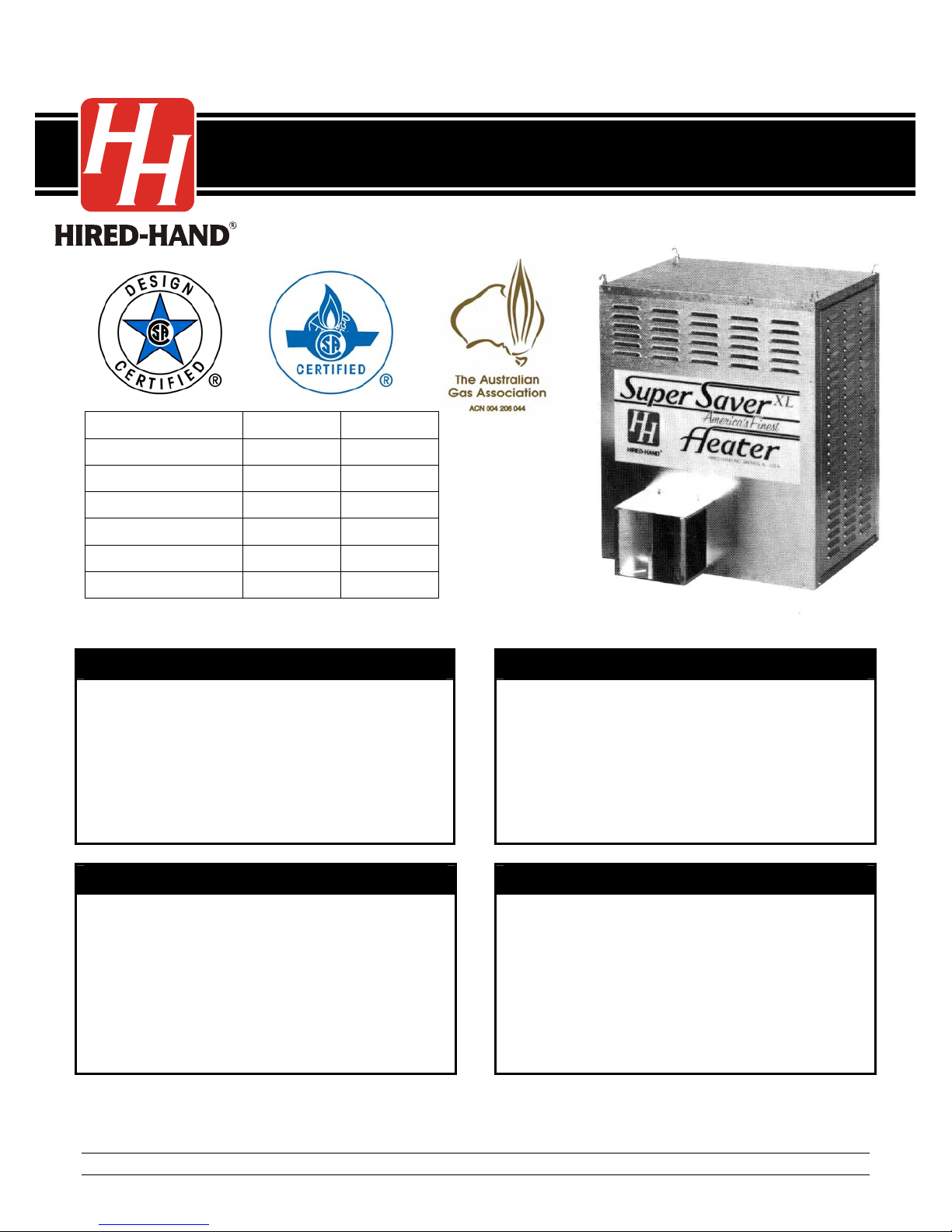
SUPER-SAVER XLTMHEATER
Agricultural Building Heater – 120 Volt
Hot Surface Ignition ♦ Wash Down Design ♦ 120 Volt (only)
FOR YOUR SAFETY
If you smell gas:
1. Open windows
2. Don’t touch electrical switches
3. Extinguish any open flames
4. Immediately call your gas supplier
CONSIGNES DE SECURITE
Si vous sentez une odeur de gaz:
1. Ouvrez les fenetres
2. Ne touchez pas aux interrupteurs electriques
3. Etegnex toute flamme hue
4. Contactez immediatement votre compangie
de gaz
Retain Instructions for Future Reference
FOR YOUR SAFETY
Do not store or use gasoline or any
flammable vapors and liquids in the
vicinity of this or any other appliance.
CONSIGNES DE SECURITE
II es interdit d′utiliser des liquides
inflammables ou degageant des
vapeurs inflammables, a proximite
de tout appareil fonctionnant au gaz
Part No. 4801-1015 Rev 6-09 Owners Manual Super-Saver XL Heater – 120 Volt
!
!
GENERAL HAZARD WARNING
Failure to comply with precautions and instructions provided with this heater can result
in death, serious bodily injury and property loss or damage from hazards of fire,
explosion, burn, asphyxiation, carbon monoxide poisoning, and/or electrical shock. If
you need assistance or heater information such as an instruction manual, labels, etc.
contact the manufacturer.
!
Keep solid combustibles, such as building materials, paper, cardboard, feathers, straw
and dust a safe distance away from the heater as recommended by the instructions.
Never use the heater in spaces which contain or may contain volatile or airborne
combustibles, or products such as gasoline, solvents, paint thinner, dust particles, or
unknown chemicals. Failure to follow these instructions may result in a fire or
explosion, property damage, personal injury or loss of life.
WARNING
WARNING
Not for home or recreational vehicle use. Installation of this heater in a home or
recreational vehicle may result in a fire or explosion, property damage, personal injury
or loss of life.
!
Proper gas supply pressure must be provided to the inlet of the appliance. Refer to
rating plate for proper gas supply pressure. Gas pressure in excess of the maximum
inlet pressure specified at the appliance inlet can cause fires or explosions, leading to
serious injury, death, building damage or loss of livestock.
WARNING
Likewise, gas pressure below the minimum inlet pressure specified at the appliance
inlet may cause improper combustion, leading to asphyxiation, carbon monoxide
poisoning and therefore serious injury or death to humans and livestock.
The intended use of this appliance is the heating of agricultural animal confinement
The electrical connections and grounding of the appliance shall be in compliance with
the National Electrical Code ANSI/NFPA 70.
Part No. 4801-1015 Rev 6-09 Super-Saver XL Heater – 120 Volt Page 2 of 25
USE OF EQUIPMENT
buildings
.
ELECTRICAL
Table Of Contents
1. Specifications And Requirements..................4
2. Warnings And Cautions.................................5
3. Maintenance And Warranty...........................6
4. Installation......................................................7
5. User Instructions............................................8
6. Outside Mount (Optional)...............................9
7. Component And Wiring Diagram.................10
8. Ladder Type Schematic Diagram................11
9. Servicing Instructions...................................12
10. Pipe Sizing Guidelines.................................17
11. Parts & Assemblies......................................19
HEATER DIMENSIONS
WEIGHT 130 lb. (60 kg)
HEIGHT 30 in. (76.2 cm)
WIDTH 24-1/2 in. (62.2 cm)
DEPTH 19-1/4 in. (48.9 cm)
Be Sure To Check Delivery!
Locate packing slip and make sure
all of the listed parts are enclosed.
If not, call your Hired-Hand
Distributor immediately.
Adjustable Wrench
Pipe Glue
Install screw hooks with hammer or drill.
Gas Leak Testing Solution
1/4″ (7 mm)
Nut Driver
MINIMUM CLEARANCES
The heater must be located a minimum of 12 inches (305 mm) from the ceiling, a minimum of 12 inches (305 mm)
from the wall on the sides and back, a minimum of 20 inches (305 mm) from the ground, and positioned such that
livestock and combustible materials are unable to come in contact with the heater or within 10 feet (3 meters) of the
hot air discharge. (See Figure 1 - Installation Instructions).
1. Specifications and Requirements
(air required to support combustion)
LP/Propane
Gas
Natural
Gas
Part No. 4801-1015 Rev 6-09 Super-Saver XL Heater – 120 Volt Page 3 of 25
Model No. Maximum Input Ventilation
SS-40-XL 40,000 BTUH (11.7 kW) 500 CFM (849.5 m3/hr)
SS-75-XL 75,000 BTUH (21.9 kW) 500 CFM (849.5 m3/hr)
HH-SS-120-XL 120,000 BTUH (35.2 kW) 1000 CFM (1699 m3/hr)
HH-SS-175-XL 175,000 BTUH (36.6 kW) 1000 CFM (1699 m3/hr)
HH-SS-200-XL 200,000 BTUH (58.6 kW) 1000 CFM (1699 m3/hr)
HH-SS-225-XL 225,000 BTUH (65.9 kW) 1000 CFM (1699 m3/hr)
Maximum 14 in. W.C. (34.8 mbar) and minimum 12.5 in. W.C. (31.1 mbar) inlet gas supply
pressure acceptable at gas regulator connection. Burner manifold pressure 11 in. W. C. (27.4
mbar) at maximum input. Gas pressure should be checked by a certified gas technician while
heater is in operation.
Maximum 14 in. W.C. (34.8 mbar) and minimum 5 in. W.C. (12.5 mbar) inlet gas supply pressure
acceptable at gas regulator connection. Burner manifold pressure of 3.5 in. W. C. (8.7 mbar) at
maximum input. Gas pressure should be checked by a certified gas technician while heater is in
operation.
Refer to heater ratings plate for unit voltage, amperage, and frequency ratings.
2. Warnings and Cautions
!
This appliance is equipped with a three prong (grounding) plug for your
protection against electrical shock and should be plugged directly into a
properly grounded three-prong receptacle. Failure to use a properly grounded
When Heater Is Connected To Remote Thermostat
Heater May Start At Any Time!
ELECTRICAL GROUNDING INSTRUCTIONS
receptacle can result in electrical shock, personal injury or death.
WARNING
CAUTION!
1. Installation must conform with local, state, and national codes, or in the absence of local codes, with the
Standard for the Storage and Handling of Liquefied Petroleum Gases, in accordance with ANSI/NFPA 58
and/or the National Fuel Gas Code, ANSI Z223.1, as applicable.
2. Follow safety, maintenance, and test firing instructions packaged with Heater.
3. Refer to model specifications label for gas type (LP or Natural Gas).
4. Check all connections for gas leaks.
5. Gas supply and regulator must be installed outside building.
6. The hose assembly should be protected from traffic, building materials, and any contact with hot surfaces
both during and while in storage.
7. Do not open heater doors, or remove a heater panel, or move or handle the heater while it is operating,
hot, or connected to power supply.
8. Turn power off before servicing. (Heater may start at any time if power is connected).
9. Heater is not recommended for heating human living quarters.
10. Not to be used for heating where flammable liquids and vapors are stored or used.
11. Inadequate gas volume and (or) pressure will directly influence the combustion efficiency of the heater.
Adequate gas volume and (or) pressure is the responsibility of the installer.
12. Adequate ventilation is required.
13. Combustion and ventilation air must not be obstructed.
14. Not for use with duct work other than types provided by manufacturer.
15. Position heater properly before us e. Heater must be level and in ac cordance with minimum clearances.
16. For safety, this heater is equipped with air flow proving switch and manual-reset high limit switch.
17. Keep temperature of fuel containers below 100° F (37.8°C). Containers must be installed outside
building.
18. Heater must not be operated for one hour following wash-down.
Part No. 4801-1015 Rev 6-09 Super-Saver XL Heater – 120 Volt Page 4 of 25
3. Maintenance and Warranty
MAINTENANCE
1. The appliance area should be kept clear & free from combustible materials, gasoline and other flammable
vapors, and liquids.
2 The flow of combustion and ventilation air must not be ob structed.
3. Your Super Saver XL Heater should be inspected before each use, and at least annually by a qu alified
service person.
4. The hose should be visually inspected prior to each use of the heater. If it is evident there is excessive
abrasion or wear or the hose is cut, it must be replaced prio r to the heater being put into operation. The
replacement hose assembly shall be that specifi ed by the manufacturer. (See parts list).
5. Inspect heater and gas connections periodically for gas leaks with an approved gas leak testing sol ution;
applying a soapy water mixture to gas connections works well. Bubble formation indicates a leak.
6. Keep heater clean at all times.
A. Open doors and blow out dust with high pressure air hose. Be sure interior of burner and flared
end are kept clean.
B. Burner orifice and hot surface ignition assembly must be kept clean and free of carbon build-up.
C. Check blower wheel regularly for dust accumulation and clean periodically for maximum airflow.
D. Thermostat coils must be kept clean to assure proper temperature control.
E. Igniter must be cool before wash down. Do not operate heater for one hour following wash-down.
WARRANTY
Your Super-Saver XL Heater has been manufactured with the finest materials and components
available, and is backed by a one-year warranty against electrical and mechanical defects in
material and workmanship. If this heater fails to operate during this period, return it intact and
prepaid to Hired-Hand, Inc., 1733 Co Rd 68, Bremen, AL 35033 for repair or replacement without
charge at the manufacturer’s option.
Damage by accident or abuse is not covered by this warranty.
This warranty gives you specific legal rights.
You may also have other rights which vary by location.
Warrantor: Hired-Hand, Inc. Bremen, AL 35033 USA
This appliance rating is based on the use of ANSI LC-2 test gases including LP (2500 BTU/ft3,
93.15 MJ/m
regarding the proper operation of this appliance when these conditions a re not met.
3
) and natural gas (1075 BTU/ft3, 40 MJ/m3). Hired-Hand, Inc. makes no guarantees
DISCLAIMER
Part No. 4801-1015 Rev 6-09 Super-Saver XL Heater – 120 Volt Page 5 of 25
4. Installation
r
4.1 Hanging The Heater
Chain Suspension Cable Suspension
Mount the heater with screw hooks and chains so that
the back of the heater is at least 12 inches (305 mm)
from the ceiling and wall. The heater must be a
minimum of 20 inches (500 mm) from floor, and
located so that livestock and combustible materials
are unable to come in contact with heater or within 10
ft (3 meters) of the hot air discharge.
4.2 Directions for Leveling
Adjust cables or chains as required
to level the heater. Use a
carpenter's level to check that the
heater is level.
4.3 Installing Dual-Flare Duct
Fold Dual-Flare duct to shape as
shown in Fig. 1. Install Dual-Flare
duct to heater exhaust (Fig. 1) as
shown with sheet metal screws
provided. This provides a multidirectional heat flow that may be set
by bending flaps.
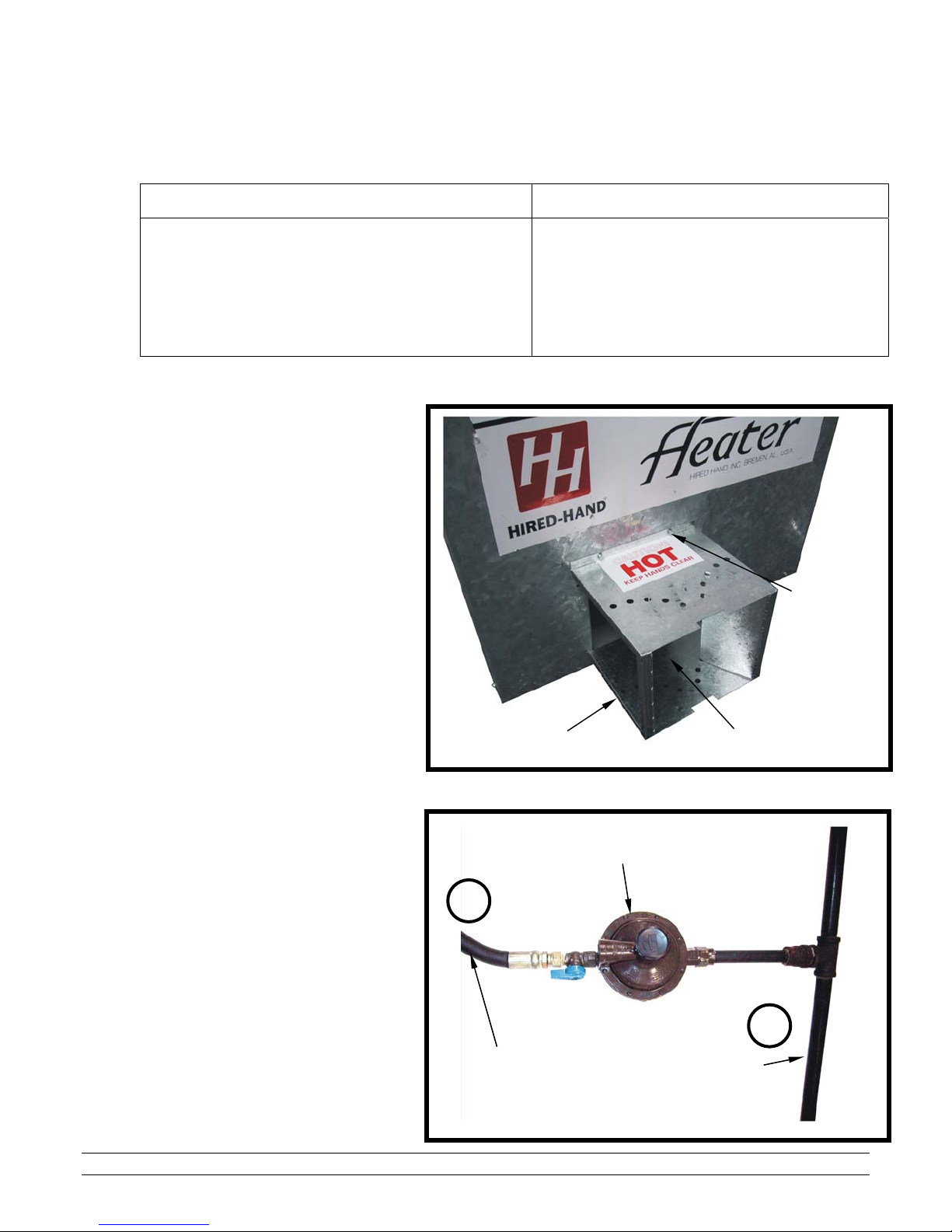
4.4 Connecting the Gas Supply
For gas connection (Fig. 2) attach
regulator to the Hi-Pressure Line (A)
at outside of building. Connect
flexible hose (B) to low pressure end
of regulator with special brass
coupling. See page 1 for LP, and
natural gas requirements.
Fig. 1
Fig. 2
B
If frequent height adjustment is required, use
cables and pulleys. Main line cable would be
connected to a winch.
Flare Duct
Gas Regulato
Fig. 2
Flexible
hose
Adjust Flap To
Direct Heat Flow
High Pressure
Line
Attach Flare
Duct To
Heater With
Sheet Metal
Screws
A
Part No. 4801-1015 Rev 6-09 Super-Saver XL Heater – 120 Volt Page 6 of 25
5. User Instructions
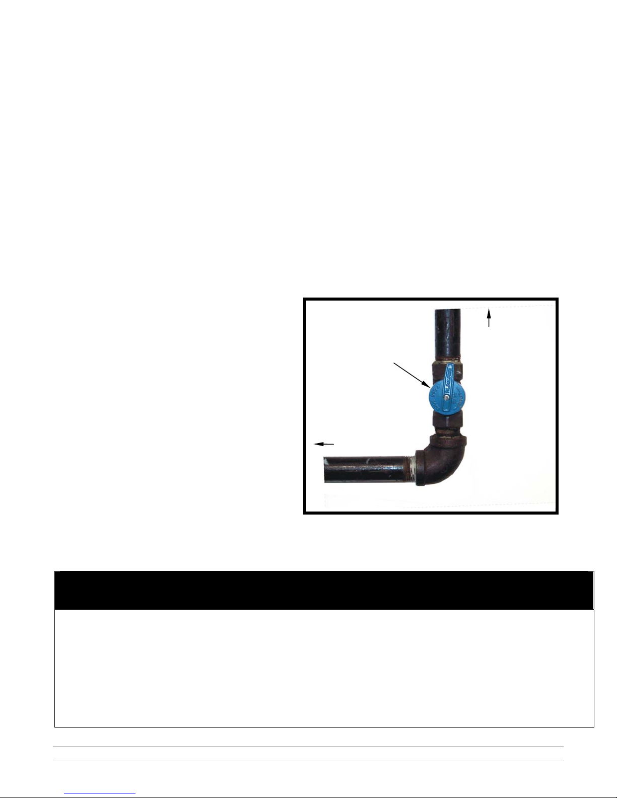
Before turning on gas, check main supply valve to be sure it is open (Fig. 3). Be sure to check all
connections for leaks with a Gas Leak Testing solution, (soap and water work well). Check to see if gas
valve knob is in the ON position. If not, turn counter-clockwise until knob “clicks” into the ON position.
(This may not apply to all units). Turn on gas by turning ball valve handle into vertical position.
5.1 Connecting Electrical Power
Make sure a circuit breaker or similar cutoff device is provided to permit disconnection of
electrical power to heater for service and cleaning. This heater is designed to be wired directly,
with no plugs and outlets necessary. All electrical work should be performed by a certified electrician.
The wiring diagrams on pages 7-8 show how to wire a line power supply directly to the heater’s
terminal block. If no adjustments are made, the heater will operate every time power is supplied and
the on/off switch is activated. If an external thermostat is to be used (See Component & Wiring
Diagram), the heater will operate only when power is supplied, the on/off switch is activated, and the
thermostat indicates a call for heat.
5.2 Starting Up
Adjust thermostat higher than house
temperature. Allow 20 seconds for
heater to ignite. On initial start up or
when heater has not been in service
for some time, heater may require
more than one attempt to purge air
and ignite heater. (IF HEATER
FAILS TO IGNITE. REFER TO
TROUBLE SHOOTING GUIDE).
Adjust thermostat to desired house
temperature.
5.3 Shutting OFF Heater
Shut off main gas supply valve, close
ball valve, and disconnect electrical
power.
Fig. 3
Gas Valve
Shown in
"ON" Position
To Heater
To Gas
Supply
In order to prevent hazardous accumulation of CO2 gases, the heater must
Ventilation requirements are given in 'Specifications and Requirements' on page 1.
Both installer and operator must ensure that the building’s ventilation rate never drops
Part No. 4801-1015 Rev 6-09 Super-Saver XL Heater – 120 Volt Page 7 of 25
CAUTION!
LIMITING EXCESS CARBON DIOXIDE (CO2 )
operate ONLY in a properly ventilated room.
below the noted limits.
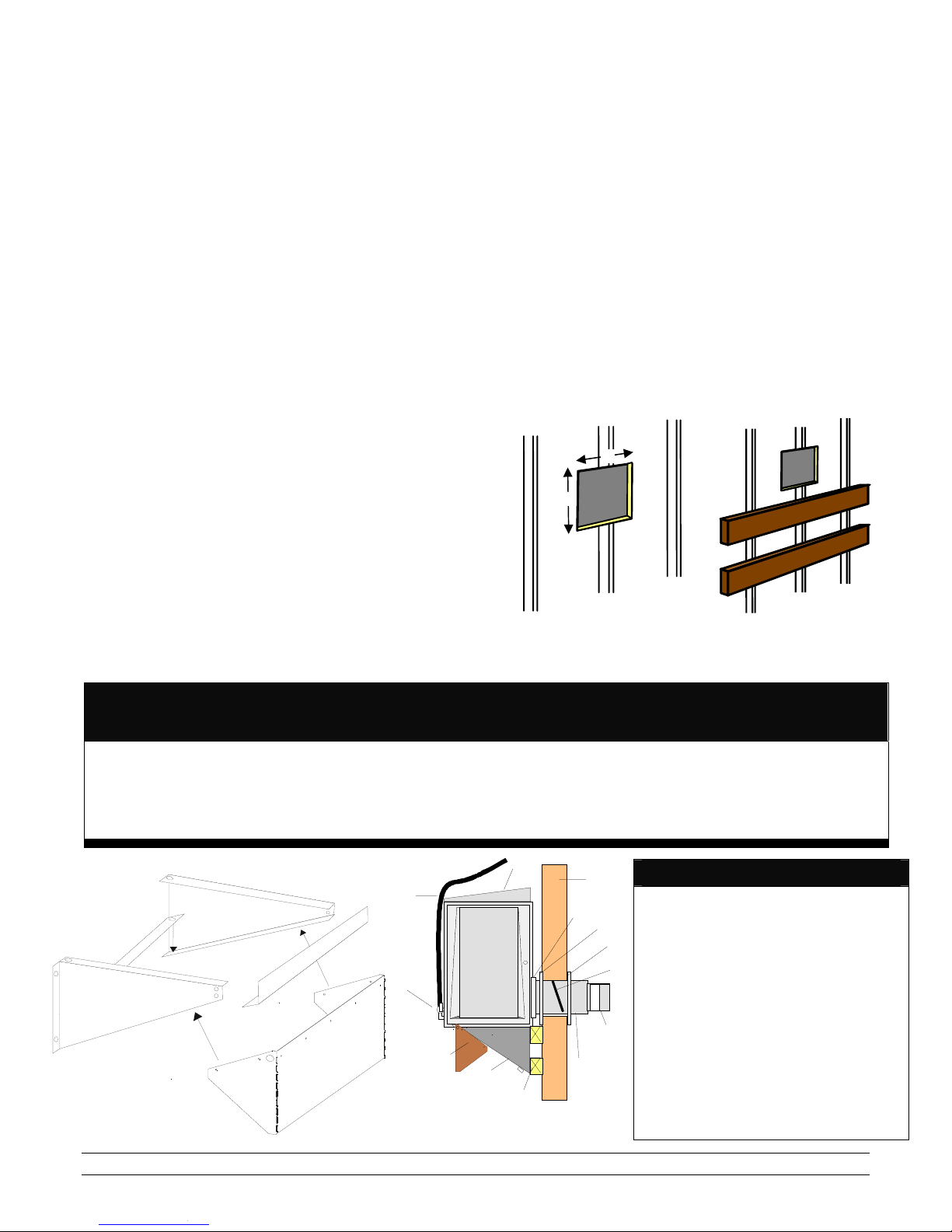
6. Outside Mount (Optional)
″
Hired-Hand heaters are available in Outs ide Mount (OSM) models. These heaters are designed to be mounted to
the outside wall of a building. This saves valuable space inside the building and ensures fresh air intake for the
heater. If you have purchased one of our OSM heaters, please read the following before install ing your new heater.
1. Before disposing of the box, cut the installation template
from the side.
2. Position template on outside of building where heater is
to be mounted. Be sure the template is level.
3. Drill 6.3 mm (1/4″) holes through all 8 X’s shown on
template. NOTE: Opening for duct measures 254 mm
(10″) width (W) x 254mm (10″) height (H). See Detail A.
4. Locate 4 X’s for thru-wall extension duct and cut from
one hole to the next until opening is removed. See Detail
A.
5. If additional support is needed, add support by fastening
two 2' x 4' boards on outside of wall where heater
support brackets are to be positioned. The two 2' x 4'
boards are to be fastened to studs inside the wall. See
Detail B.
6. Assemble heater support bracket as shown in Detail C.
7. Attach Insert thru-wall extension duct assembly through
opening in wall. The ‘varmint’ flap, located inside the
thru-wall extension duct, should be positioned as shown
in Detail D.
8. Bend extension duct mounting flange into a rectangle
and fasten around exhaust outlet on front of heater with
sheet metal screws provided.
9. Place heater on support bracket. Support bracket must
be level before heater is set in place.
10. Slide thru-wall extension duct assembly into flange,
and secure with sheet metal screws.
11. Place outer flashing seal around thru-wall extension
duct and secure with sheet metal screws to inside
of wall.
12. Fasten directional duct to extension duct mounting
flange, then bend deflectors until they force heated
air in the desired direction.
13. To continue with installation of your heater, see
‘User Instructions’ section on the next page.
Detail A
Detail B
W
H
W = 254 mm (10
H = 254 mm (10″)
)
CAUTION!
The minimum side clearance to combustible walls must be 305 mm (12 inches).
The minimum clearance between the appliance and rear wall must be 305 mm (12 inches).
Weeds, snow, or other materials must not be allowed to accumulate on heater or adjacent to heater. Heat er and thru-
Part No. 4801-1015 Rev 6-09 Super-Saver XL Heater – 120 Volt Page 8 of 25
wall extension duct must be a minimum of 500 mm (20 inches) above ground and out of reach of livestock.
Detail C
Detail D
9
5
2
3
14
4
10
1
8
6
1. Wall (By others)
2. Rain shield, included with OSM heater.
3. Door, included with OSM heater.
13
4. Mounting brace, included with OSM kit.
12
5. Gas shutoff valve, included with heater.
11
6. Thru-wall extension duct, included with OSM kit.
7. Dual flare duct. Use T-duct included with heater
or use optional OSM Y-duct ordered separately.
8. Extension flange, included with OSM kit.
7
9. Gas hose, optional ordered separately.
10. 2 x 4 Framing for Brace, not included
11. ‘Varmint’ flap, included with OSM kit.
12. Inner flashing seal, included with OSM kit.
13. Outer flashing, included with OSM kit.
14. Wind Guard, included with OSM kit.
Legend
 Loading...