


SLS
SLS----500
SLSSLS
Master Controller
Master Controller
Master ControllerMaster Controller
Graphical programing with
SLS-500-Configurator
500
500500
SLS-500 Master Controller
Software manual
www.hiquel.com

HIQUEL
HIQUEL SLS-500-Configurator
HIQUELHIQUEL
Herbert Weiß, Helmut Maurer:
SLS-500 Master Controller – User Manual
Version: 4.03
Great care has been taken in the creation of the text,
illustrations and program examples in this manual. Neither
HIQUEL, there authors nor their interpreters may be held
responsible for any errors herein, nor can they be held
responsible or liable for cons equences arising from any errors
herein.
This manual is subject to copyright law. All rights are reserved.
This manual may not be copied in part or whole in any form
including electronic media without the written consent of
Hiquel. Neither may it be transferred in any other language
suitable for machines or data processing facilities. Also rights
for reproduction through lecture, radio or television
transmission are reserved.
Hiquel copyrights this documentation and the accompanying
software.
Copyright 2002-2004 by HIQUEL GmbH
www.hiquel.com 2

HIQUEL
HIQUEL SLS-500-Configurator
HIQUELHIQUEL
Attention! You are handling
dangerous electrical current!
Disconnect the supply voltage before making any wiring modifications.
Ensure that the system cannot be switched on accidentally.
Ensure that the device and its surroundings are potential free.
Please refer to the specific installation and mounting instructions.
Qualified personal only should handle the device.
The device has to be mounted in such a way that no unintentional
operation may occur.
All control and supply voltage wiring must be routed so that no
inductive or capacitive interferenc e or any other severe electric al noise
disturbance may interfere with the device.
Supply voltage variation must not exceed the specifications in the
technical details. If so, proper performance of the device cannot be
guaranteed.
Emergency installations according to EN60204/IEC204 (VDE0113)
must remain active in all modes of the automated installation.
Activation of the emergency installation must not cause an
uncontrolled or undefined start cycle.
The software engineer has to make sure, that no failure func tions of
the automated installation may occur when line faults or core faults
arise.
Notwithstanding the above, local regulations must be observed in all
installations.
www.hiquel.com 3

HIQUEL
HIQUEL SLS-500-Configurator
HIQUELHIQUEL
Content
ATTENTION! YOU ARE HANDLING DANGEROUS ELECTRICAL
CURRENT!.................................................................................................3
CONTENT..................................................................................................4
SLS-500 MASTER CONTROLLER.........................................................14
PREFACE ................................................................................................15
SYSTEM REQUIREMENTS.....................................................................16
CREATE NEW PROJECT .......................................................................17
Start PowerPoint..........................................................................17
Open SLS-500-Configurator sample...........................................17
Save new project.........................................................................18
Start presentation (press F5).......................................................19
SLS-500-Configurator does not respond.....................................20
SLS-500-Configurator responds successfully.............................20
IMPORTANT ADVICE.................................................................21
CONFIGURATION...................................................................................22
Configuration page......................................................................22
Add objects..................................................................................23
Delete objects..............................................................................24
Program object priority ................................................................25
Define in/outputs..........................................................................25
PROJECT.................................................................................................26
Project:Info ..................................................................................26
Project:Import..............................................................................27
Project: Update I/Os....................................................................28
PAGES.....................................................................................................29
Page: Zoom all ............................................................................29
www.hiquel.com 4

HIQUEL
HIQUEL SLS-500-Configurator
HIQUELHIQUEL
Page: Zoom 100%.......................................................................29
Page: Zoom 75%.........................................................................29
Page: Zoom 60%.........................................................................29
Page: New...................................................................................29
Page: Del.....................................................................................30
Page: Copy..................................................................................31
Page: Ignore................................................................................31
Page: Go to .................................................................................32
Page: Execute.............................................................................33
PAGE EXECUTION .................................................................................34
Standard page.............................................................................34
Page/Execute/every 1ms.............................................................36
Page/Execute/every 10ms...........................................................36
Page/Execute/every 100ms.........................................................36
Page/Execute/clock every second...............................................37
Page/Execute/clock every minute ...............................................37
Page/Execute/clock every hour...................................................37
Page/Execute/clock every day ....................................................38
Page/Execute/clock every Week.................................................38
Page/Execute/clock every Month................................................38
Page/Execute/clock every Year...................................................39
Page/Execute/only for initialisation..............................................39
Page/Execute/on binary memory ................................................39
Page/Execute/on analogue memory ...........................................40
CONNECTIONS.......................................................................................41
Creation.......................................................................................41
Mind the direction of the arrow....................................................41
Create connections......................................................................42
Change the style of the line.........................................................43
DATA TYPES OF SLS-500-CONFIGURATOR .......................................44
www.hiquel.com 5

HIQUEL
HIQUEL SLS-500-Configurator
HIQUELHIQUEL
Bit data ........................................................................................44
Analogue data .............................................................................44
Text data......................................................................................44
CONSTANTS OF SLS-500-CONFIGURATOR .......................................45
Binary constants..........................................................................45
Analogue constants.....................................................................47
Text constants.............................................................................49
SPECIAL FLAGS .....................................................................................51
Special flag: START....................................................................51
Special flag: every 1ms ...............................................................51
Special flag: every 10ms .............................................................52
Special flag: every 100ms ...........................................................52
Special flag: Clock every second.................................................52
Special flag: Clock every minute .................................................53
Special flag: Clock every hour.....................................................53
Special flag: Clock every day.......................................................53
Special flag: Clock every week....................................................53
Special flag: Clock every month..................................................54
Special flag: Clock every year.....................................................54
MEMORIES..............................................................................................55
Bit memory ..................................................................................56
SET bit memory...........................................................................56
RESET bit memory......................................................................56
TOGGLE bit memory...................................................................57
Analogue memory .......................................................................58
IF rising edge SET analogue memory.........................................59
IF falling edge SET analogue memory........................................60
IF both edges SET analogue memory.........................................60
IF permanent high SET analogue memory .................................60
IF permanent low SET analogue memory...................................61
www.hiquel.com 6

HIQUEL
HIQUEL SLS-500-Configurator
HIQUELHIQUEL
Text memory ...............................................................................61
IF rising edge SET text memory..................................................62
IF falling edge SET text memory.................................................62
IF both edges SET text memory..................................................63
IF permanent high SET text memory ..........................................63
IF permanent low SET text memory............................................63
BINARY OPERATORS ............................................................................65
Binary operator: Binary AND.......................................................65
Binary operator: Binary OR..........................................................66
Binary operator: Binary EXCLUSIVE OR ....................................67
Binary operator: Binary NEGATION............................................68
Binary operator: Rising edge.......................................................68
Binary operator: falling edge........................................................69
Binary operator: Both edges........................................................69
Binary operator: Split...................................................................70
ANALOGUE OPERATORS......................................................................71
Analogue operator: Addition........................................................71
Analogue operator: Subtraction...................................................72
Analogue operator: Multiplication ................................................73
Analogue operator: Division ........................................................73
Analogue operator: Modulo (read part of a value)................74
Analogue operator: Shift left........................................................75
Analogue operator: Shift right......................................................75
Analogue operator: Greater than.................................................76
Analogue operator: Greater or equal...........................................77
Analogue operator: Equal............................................................77
Analogue operator: Not equal......................................................78
Analogue operator: Less or equal ...............................................79
Analogue operator: Less .............................................................79
www.hiquel.com 7

HIQUEL
HIQUEL SLS-500-Configurator
HIQUELHIQUEL
Analogue operator: Logical AND.................................................80
Analogue operator: Logical OR...................................................81
Analogue operator: Logical NOT.................................................81
Analogue operator: Split..............................................................82
TEXT OPERATORS ................................................................................83
Text operator: Combine text........................................................83
Text operator: Greater.................................................................84
Text operator: Greater or equal...................................................84
Text operator: Equal....................................................................85
Text operator: Not equal..............................................................85
Text operator: Less or equal .......................................................86
Text operator: Less .....................................................................87
Text operator: Split......................................................................87
Text operator: Sub String ............................................................88
Text operator: Left String.............................................................89
Text operator: Right String ..........................................................90
Text operator: String Length........................................................91
COUNTER................................................................................................92
Counter: Count Up.......................................................................92
Counter: Count Down..................................................................93
Counter: Count Set......................................................................94
Counter: Count up with limit ........................................................95
Counter: Count down with limit....................................................96
CONVERSION.........................................................................................98
Conversion: Binary->Analogue....................................................98
Conversion: Analogue->Binary....................................................99
Conversion: Analogue Scale.....................................................101
Conversion: Text->Analogue.....................................................102
Conversion: Analogue->Text.....................................................104
Format characters .....................................................................105
www.hiquel.com 8

HIQUEL
HIQUEL SLS-500-Configurator
HIQUELHIQUEL
STATES .................................................................................................106
State: Select alternative function state......................................106
Analogue state frame ................................................................107
Binary state................................................................................108
Example: STATE - Select alternative function ..........................109
COMMENTS ..........................................................................................110
Insert comment..........................................................................110
SYMBOLIC GROUPS............................................................................111
Create symbolic groups.............................................................111
SYSTEM MEMORY ...............................................................................112
System: Binary memory ............................................................113
System: IF input is One SET binary memory ............................113
System: IF input is One DELETE binary memory .....................113
System: IF input is One INVERT binary memory......................114
System: Analog memory ...........................................................115
System: Text memory...............................................................115
System: System variable table..................................................116
INCREMENTAL ENCODER...................................................................117
The Incremental Encoder..........................................................117
Programming an incremental encoder......................................118
I/O...........................................................................................................120
I/O: Digital Inputs.......................................................................120
I/O: Digital Outputs....................................................................121
I/O: Analogue Inputs..................................................................123
I/O: Analogue Outputs...............................................................124
I/O: Potentiometer .....................................................................126
GROUPS................................................................................................128
Export groups............................................................................128
Import groups ............................................................................129
Delete groups............................................................................129
www.hiquel.com 9

HIQUEL
HIQUEL SLS-500-Configurator
HIQUELHIQUEL
Adjust controller.........................................................................130
The PID – Controller..................................................................131
Transmission-function of a PID – controller ..............................131
OBJECTS...............................................................................................133
Objects: Timer...........................................................................133
Objects: Timer: ON delay..........................................................135
Objects: Timer: OFF delay ........................................................135
Objects: Timer: ON OFF delay..................................................135
Objects: Timer: ON pulse..........................................................136
Objects: Timer: OFF pulse........................................................136
Objects: Timer: ON OFF pulse..................................................136
Objects: Timer: Recycler high first ............................................137
Objects: Timer: Recycler low first..............................................137
Objects: Timer: Delay................................................................137
REAL TIME CLOCK...............................................................................138
Objects: clock: Exact time.........................................................138
Objects: clock: Time period.......................................................139
Objects: clock: Exact date.........................................................139
Objects: clock: Date period .......................................................139
Objects: clock: Exact date&time................................................140
Objects: clock: Date&time period..............................................140
Objects: clock: Exact Weekday.................................................141
Objects: clock: Weekday period................................................141
Objects: clock: Exact Week ......................................................141
Objects: clock: Week Period .....................................................142
Objects: clock: Analogue: Time.................................................142
Objects: clock: Analogue: Date .................................................143
Objects: clock: Analogue: Day of Week....................................143
Objects: clock: Analogue: Week of year...................................143
Objects: clock: Text: Time.........................................................144
www.hiquel.com 10

HIQUEL
HIQUEL SLS-500-Configurator
HIQUELHIQUEL
Objects: clock: Text: Date .........................................................144
Objects: clock: Text: Date&Time...............................................144
Objects: clock: Text: Day of Week ............................................145
Objects: clock: Text: Week of year ...........................................145
CAN OBJECTS (CANBUS)....................................................................146
Objects: CAN Message In.........................................................146
Objects: CAN Value In...............................................................147
Objects: CAN Text In.................................................................147
Objects: Receive FULL CAN Message .....................................148
Objects: CAN Message Out ......................................................148
Objects: CAN Value Out............................................................149
Objects: CAN Text Out..............................................................149
Objects: Send FULL CAN message..........................................150
SIO FUNCTIONS (SERIAL INPUT/OUTPUT).......................................151
Objects: SIO: Send Text............................................................151
Objects: SIO: Send Byte............................................................152
Objects: SIO: Send Word..........................................................152
Objects: SIO: Send DWord .......................................................152
Objects: SIO: Receive Byte.......................................................153
Objects: SIO: Receive Text.......................................................153
TERMINAL FUNCTIONS (MMI).............................................................154
Objects: Terminal: Show Message............................................154
Objects: Terminal: Show Value.................................................156
Objects: Terminal: Show Text...................................................157
Objects: Terminal: Edit Text......................................................158
Objects: Terminal: Edit Value....................................................160
Objects: Terminal: Menu ...........................................................162
Objects: Terminal: Select item ..................................................164
Objects: Terminal: Update Value ..............................................166
Objects: Terminal: Update Text ................................................167
www.hiquel.com 11

HIQUEL
HIQUEL SLS-500-Configurator
HIQUELHIQUEL
Objects: Terminal: Key pressed ................................................167
MEMORY CARD....................................................................................169
Objects: MemoryCard: Read Value into SLS500 memory........169
Objects: MemoryCard: Read Text into SLS500 memory..........170
Objects: MemoryCard: Write Value to card...............................170
Objects: MemoryCard: Write Text to card.................................171
Objects: MemoryCard: Read Value from card ..........................171
Objects: MemoryCard: Read Text from card ............................172
Objects: MemoryCard: Write Analogue Value...........................172
Objects: MemoryCard: Write Text Value...................................173
SMS........................................................................................................174
Objekte: SMS: Start new short message ..................................174
Objects: SMS: Add Text to short message ...............................175
Objects: SMS: Send short message via GSM...........................175
Objects: SMS: Call Phone.........................................................176
Objects: SMS: Short message received....................................176
Objects: SMS: Check short message Text ...............................177
Objects: SMS: Skip short message blanks ...............................177
Objects: SMS: Get short message Analogue Value..................178
Objekte: SMS: Get short message Text....................................179
DEBUG...................................................................................................180
Debug: Add Symbols.................................................................180
Debug: Add Monitor...................................................................181
Debug: Monitor Binary Memory.................................................181
Debug: Monitor Analogue Memory............................................182
Debug: Monitor Text Memory....................................................182
Debug: Set Breakpoint ..............................................................182
Debug: Delete Breakpoint .........................................................183
Debug: Display System Information..........................................183
RUN........................................................................................................184
www.hiquel.com 12

HIQUEL
HIQUEL SLS-500-Configurator
HIQUELHIQUEL
Run: Compile.............................................................................184
Error during compilation ............................................................184
Compilation successful..............................................................185
Run: Simulate............................................................................185
Run: Download & Run...............................................................186
Run: Start ..................................................................................186
Run: Stop...................................................................................186
Run: Erase.................................................................................186
Run: Show.................................................................................186
Read/write binary memory.........................................................190
Read/write analogue memory....................................................190
Read/write text memory.............................................................190
SPS not found ...........................................................................191
Choose serial port .....................................................................191
Online Data exchange...............................................................194
Memory read/write.....................................................................194
SIMULATOR ..........................................................................................195
Start simulation..........................................................................195
Simulation: Binary Memory........................................................196
Simulation: Analogue Memory...................................................197
Simulation: Text Memory...........................................................198
Simulation: Logging...................................................................199
Close Simulator.........................................................................200
Continue Simulator....................................................................200
Exit Simulator ............................................................................200
CONTACT..............................................................................................201
www.hiquel.com 13
HIQUEL
HIQUEL SLS-500-Configurator
HIQUELHIQUEL
SLS-500 Master Controller
Safety precautions
Danger to life through electrical c urrent!
Only skilled personal trained in electro-engineering should
perform the des cribed steps in the following chapters. Please
observe the country specific rules and standards. Do not
perform any electrical work while the device is connected to
power.
Pay attention to following rules
Switch off the automated installation.
Disable any automatic restart system
Electrically isolate the installation
Cover any non-isolated areas
www.hiquel.com 14

HIQUEL
HIQUEL SLS-500-Configurator
HIQUELHIQUEL
Preface
„Der Grund, warum die Menschen ihre Dienste zum
Geschenk m achen, ist der Wunsch, etwas zu tun, was – vielleicht
im Gegensatz zu ihrer täglichen Arbeit - wirklich zählt!“
Charles Trueheart
www.hiquel.com 15

HIQUEL
HIQUEL SLS-500-Configurator
HIQUELHIQUEL
System Requirements
System specification for SLS-500-Configurator:
Your system must meet the following requirements to run SLS-
500-Configurator:
A free serial RS232 port (COM1 - COM8)
A previously installed version of Microsoft PowerPoint
in version Office 2000 or Office XP
Processor: 90 - 166 Pentium
RAM: min. 16 MB (32 MB for Win NT)
opt. 64 MB (128 MB for Win NT)
Free memory: min. 20 MB
opt. 40 MB
®
www.hiquel.com 16
HIQUEL
HIQUEL SLS-500-Configurator
HIQUELHIQUEL
Create new project
SLS-500-Configurator requires Microsoft PowerPoint.
Start PowerPoint
To work with SLS-500-Configurator you have to start
PowerPoint first. Then open the file SLS-500-
Configurator.ppt.
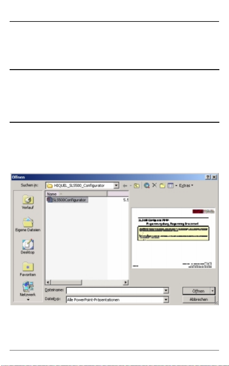
Open SLS-500-Configurator sample
Proceed as follows: After starting PowerPoint choose
File/Open from the menu. Then choose the folder SLS-500Configurator from the file dialogue. You will find the file SLS500-Configurator.ppt.
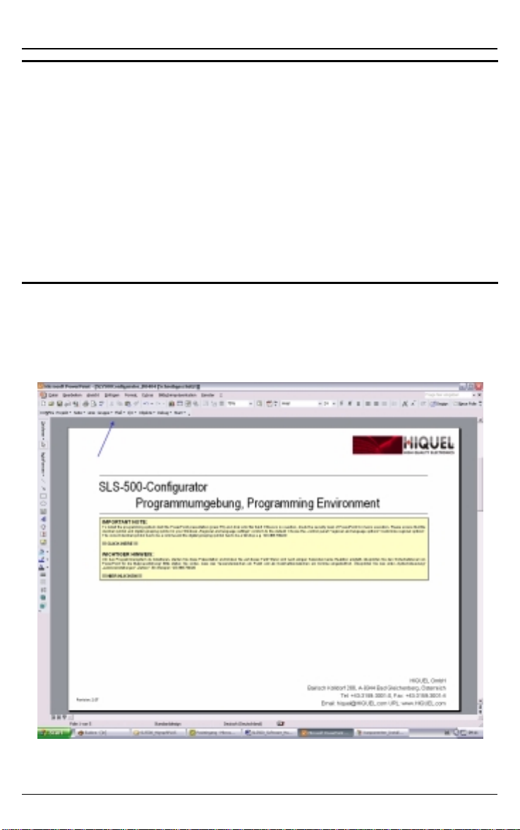
Open the file. The following screen will be displayed.
www.hiquel.com 17

HIQUEL
HIQUEL SLS-500-Configurator
HIQUELHIQUEL
Save new project
Save the presentation under the project nam e of your choice in
a file of your choice. To do these choose from the menu the
entry file/save. The window shown below appears. Enter „My
first project“ f or example and confirm the input by click ing the
save command button.
www.hiquel.com 18

HIQUEL
HIQUEL SLS-500-Configurator
HIQUELHIQUEL
Start presentation (press F5)
In order to install the components necessary for SLS-500Configurator you must start the presentation. Choose ‘Slide
Show’/’View show’ from the menu options. Now the start page
opens. Click in the black-bordered frame:
SLS-500-Configurator now installs all necessary components
and confirms it has started with the following message:
www.hiquel.com 19
HIQUEL
HIQUEL SLS-500-Configurator
HIQUELHIQUEL
SLS-500-Configurator does not respond
If you have no response from SLS-500-Configurator after a
half-minute, it is probably that your PowerPoint settings do not
allow macros to run.
You can change this setting in the menu option
‘Tools’/’Macro’/’Security’. If you chose the security level high,
no macros are car ried out. To activate the m acros you have to
choose a security level of medium or low. If you choose
medium PowerPoint will question while loading whether
macros may become carried out or not.
SLS-500-Configurator responds successfully
Now you can see an additional menu bar on your PowerPoint
screen, which includes all com ponents necessary to work with
SLS-500-Configurator:
Now you can start with the program creation!
www.hiquel.com 20

HIQUEL
HIQUEL SLS-500-Configurator
HIQUELHIQUEL
IMP ORTANT ADVICE
Do not delete any objects of this PowerPoint presentation
except those you have created yourself. If you do you will
endanger the function of the SLS-500-Configurator program!!!
www.hiquel.com 21
HIQUEL
HIQUEL SLS-500-Configurator
HIQUELHIQUEL
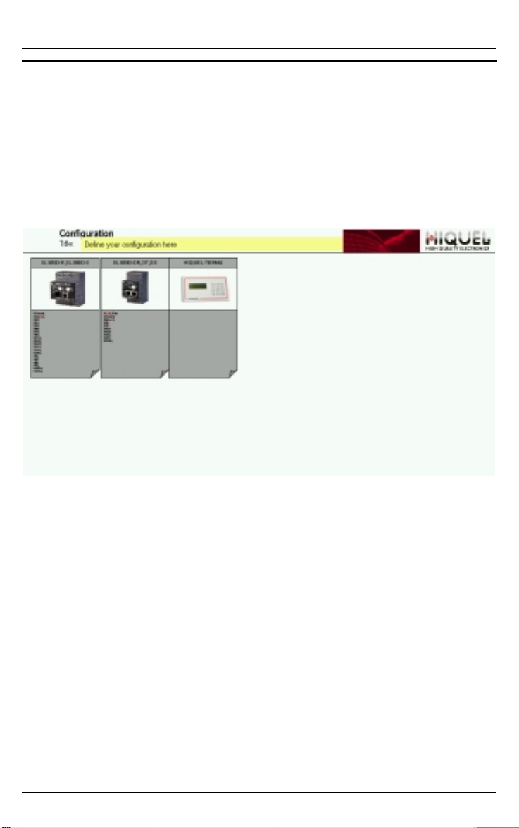
Configuration
Before you can draw a program plan with SLS-500Configurator you must define a current configuration of your
SPS System. Choose menu option CONFIGURATION. The
following configuration page appears:
Configuration page
Newer software may show additional modules
Only the modules selected for your system m ust be physically
connected in order to guarantee the correct function of the
program.
www.hiquel.com 22
HIQUEL
HIQUEL SLS-500-Configurator
HIQUELHIQUEL
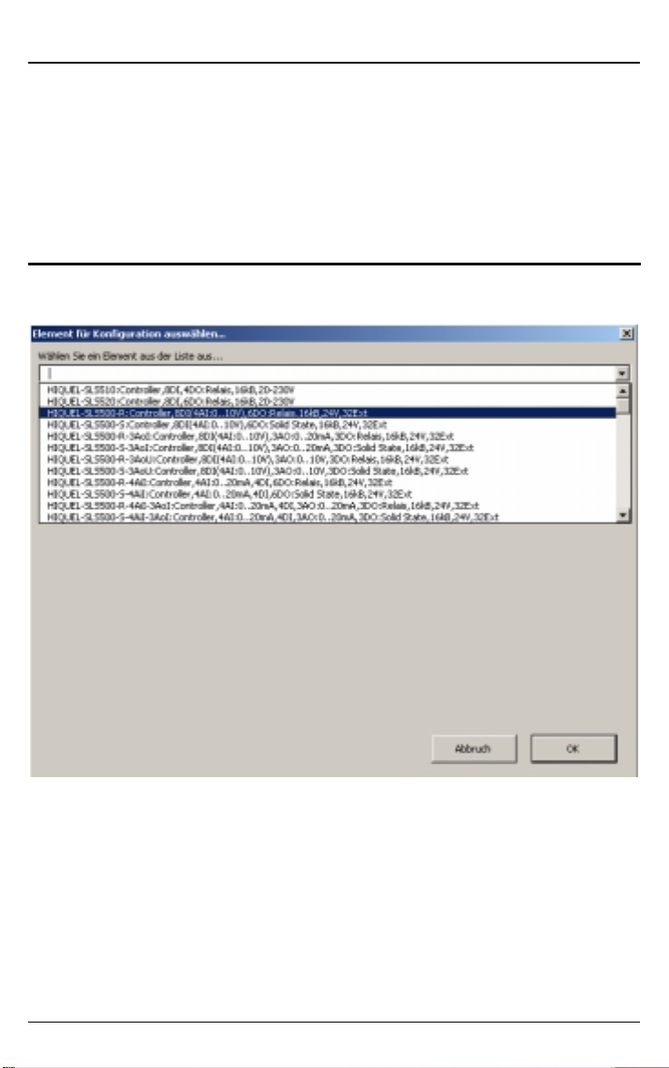
Add objects
In order to add a new expansion module to the current
configuration select the des ired module from the configuration
page and click OK:
The following display shows a system with 1 x SLS-500 base m odule, 1 x
Analogue I/O module and 1 x Term 4 MMI.
Every newly selected module will appear on the upper left of
the page on top of the SLS500 base module graphic. You must
drag and drop the module into the pos ition you require in order
of priority within the program.
ADVICE: You can also adjust the communication speed of SLS-500
Master Control Modules. Choose Fast, Norm al and Slow in the
Priority drop-down menu.
Fast: The module scans the system every 10ms.
Normal: The module scans the system every 100ms.
Slow: The module scans the system every second.
www.hiquel.com 23

HIQUEL
HIQUEL SLS-500-Configurator
HIQUELHIQUEL
When new module added:
after new position selected!
Delete objects
Select the desired module and delete it by pressing Del.
ADVICE: The module will only be deleted in the configuration page. Any
programmed object of the deleted module will not be deleted
from your program! This will be detected when you attempt to
compile your program. These objects must be deleted
manually
www.hiquel.com 24
HIQUEL
HIQUEL SLS-500-Configurator
HIQUELHIQUEL
Program object priority
SLS-500-Configurator interprets the priority of the program
objects from lef t to right and f rom top to bottom of the program
page. The remote numbers are allocated exactly the same
way. The base module has the definition L1. All expansion
modules have the definition Remote. Beginning with a
continuous number from 1. R1 is the fir st expansion; R2 is the
second and so on.
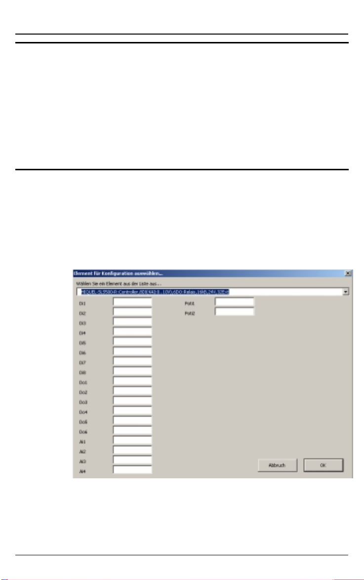
Define in/outputs
If you add a module to the configuration, you can define a
name for every digital or analogue input and output. When you
use the input or output, the spec ified name will be displayed.
This causes better understanding while programming.
www.hiquel.com 25
HIQUEL
HIQUEL SLS-500-Configurator
HIQUELHIQUEL
Project
SLS-500-Configurator makes creating information’s and copies
of projects easy. You have it all clearly on your start up page.
Choose Project from the menu to get to all relevant program
functions:
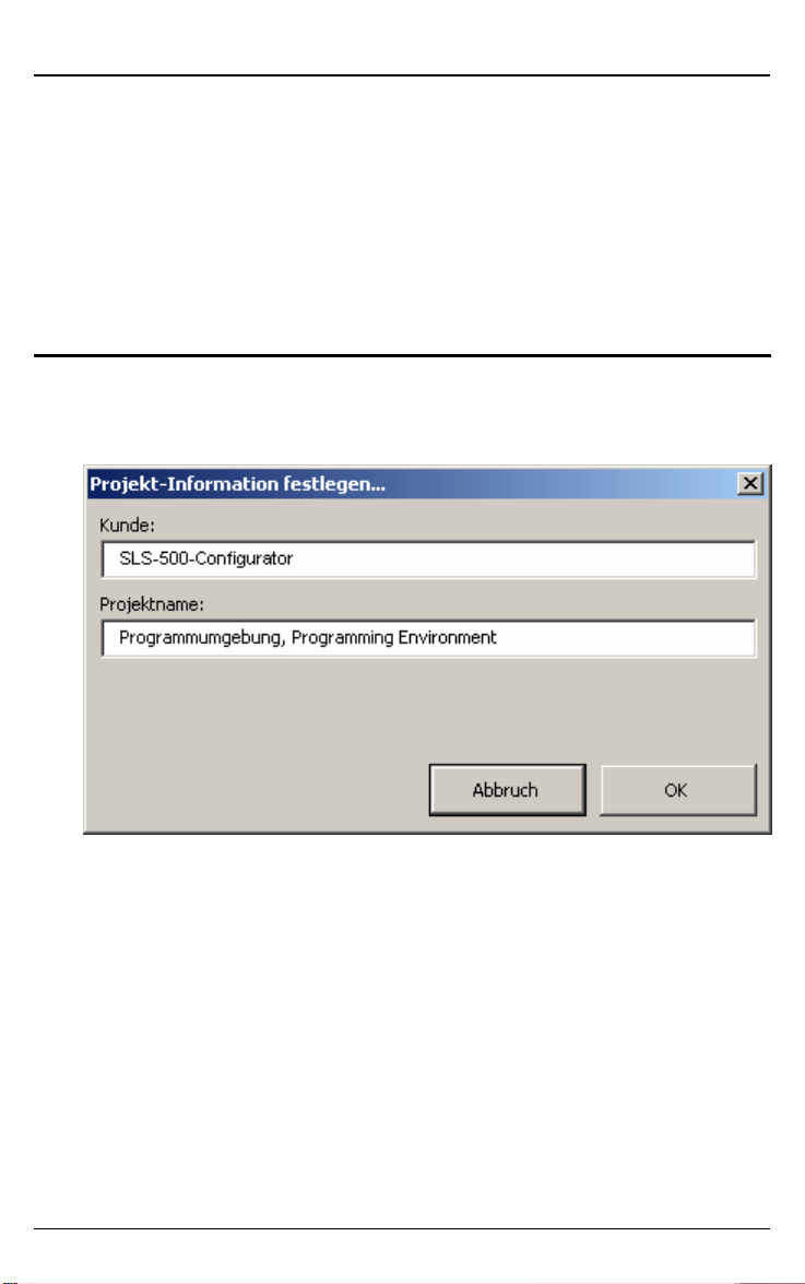
Project: Info
Choose Project-Info to get to the following dialog:
Use this function to edit the customer name and the project
name on the starting page. To set the adjustments click the
OK button.
www.hiquel.com 26
HIQUEL
HIQUEL SLS-500-Configurator
HIQUELHIQUEL
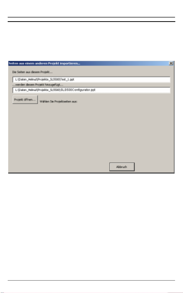
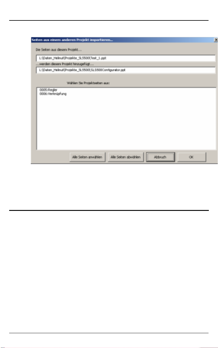
Project: Import
Choose this function to impor t a page from another projec t into
your current project.
The following dialog will appear:
Click the x button to abort the process, otherwise click on
Open Project.
www.hiquel.com 27
HIQUEL
HIQUEL SLS-500-Configurator
HIQUELHIQUEL
The page number and the page name will be displayed.
Now choose the desired page of the project from the list.
After clicking the OK button the s elected page will be put into
your current project!
Project: Update I/Os
You can edit the already set descriptions of the inputs and
outputs with one entry. The change of the descriptions has to
be accomplished on the configuration page.
After updating the I/O names the description of the in- and
outputs from the configuration page will correspond with the
whole project again.
Choose Update I/Os from the menu to start the update.
www.hiquel.com 28

HIQUEL
HIQUEL SLS-500-Configurator
HIQUELHIQUEL
Pages
SLS-500-Configurator enables you to draw as many complex
graphs as desired over as many pages as you want. Choose
the menu option Page to get to the following options:
Page: Zoom all
The active page will be displayed completely screen filling.
Page: Zoom 100%
The page will be displayed with a zoom factor of 100%
Page: Zoom 75%
The page will be displayed with a zoom factor of 75%.
Page: Zoom 60%
The page will be displayed with a zoom factor of 60%.
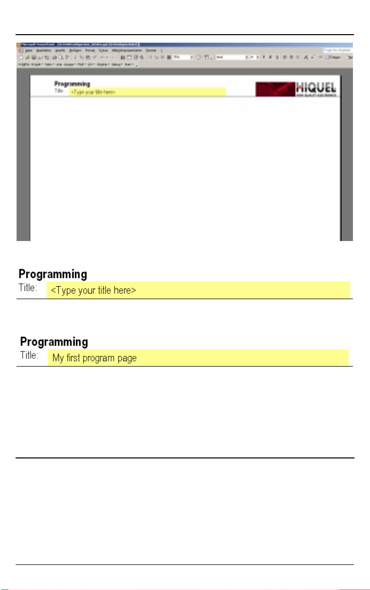
Page: New
SLS-500-Configurator places a new program ming page before
the active page. Therefore if you want to insert a new page
after the active page you must advance one page before
inserting the new page
www.hiquel.com 29
HIQUEL
HIQUEL SLS-500-Configurator
HIQUELHIQUEL
Now define the title of the new programming page:
For this you have to click into the text field and type in the text:
INFO: You can spread your program over as many SLS-500-
Configurator pages as desired!
IMPORTANT: SLS-500-Configurator programs can only be drawn on
programming pages . All other PowerPoint pages will be left
out during compilation.
Page: Del
With this command you can delete the active SLS-500Configurator programming page. After choosing this menu
option the following message occurs:
www.hiquel.com 30

HIQUEL
HIQUEL SLS-500-Configurator
HIQUELHIQUEL
If you press yes the page will be deleted and lost forever.
Press No to cancel.
Page: Copy
The active page will be copied with this command.
Page: Ignore
Use this comm and to leave out the whole content of the page
during the next compilation.
To warn you of this, UNUSED will be written cross the page.
Select this com mand a second time, UNUSED will disappear
and the page will be included again with the next compilation.
www.hiquel.com 31

HIQUEL
HIQUEL SLS-500-Configurator
HIQUELHIQUEL
Page: Go to
With this command you can quickly jump to another page of
the project. SLS-500-Configurator shows you a detailed
overview of all pages with page numbers and titles. J ust click
onto the desired page and press OK. The page will display
immediately!
www.hiquel.com 32

HIQUEL
HIQUEL SLS-500-Configurator
HIQUELHIQUEL
Page: Execute
You can select the execution rate or variable dependant
operation of each SLS-500-Configurator page with this menu
option. The following dialogue will occur:
For further details read chapter Page execution!
www.hiquel.com 33

HIQUEL
HIQUEL SLS-500-Configurator
HIQUELHIQUEL
Page execution
This chapter deals with the various types of SLS-500Configurator page execution.
Standard page
A regular SLS-500-Configurator page is created with the
command Page/New. If you create a procedure on this page,
as shown below, the page will be executed permanently.
This means that SLS500 executes the page as often as it is
possible bearing in mind program length and other program
priorities.
You can also select the execution of the page by adding an
execution format.
Choose Page/Execute from the menu to get to the following
dialogue:
www.hiquel.com 34

HIQUEL
HIQUEL SLS-500-Configurator
HIQUELHIQUEL
After choosing an execution format the setting will be displayed
on the top right of the page.
www.hiquel.com 35

HIQUEL
HIQUEL SLS-500-Configurator
HIQUELHIQUEL
To delete the execution format, you just have to click the
symbol on the top right and press the key Del.
Choose from the following execution formats:
Page/Execute/every 1ms
cyclic
cyclic
every
every
1ms
1ms
Symbol:
Function: The page will be executed every 1ms. This function is not
available with all SLS500 types!
Page/Execute/every 10ms
cyclic
cyclic
every
every
10ms
10ms
Symbol:
Function: The page will be executed every 10ms.
Page/Execute/every 100ms
cyclic
cyclic
every
every
100ms
100ms
Symbol:
Function: The page will be executed every 100ms.
www.hiquel.com 36

HIQUEL
HIQUEL SLS-500-Configurator
HIQUELHIQUEL
Page/Execute/clock every second
CLOCK
Symbol:
Function: The page will be executed exactly every second. The func tion
is only available with SLS500, which have a real time clock.
Page/Execute/clock every minute
Symbol:
Function: The page will be executed exactly every minute. The function
is only available with SLS500, which have a real time clock.
CLOCK
every
every
second
second
CLOCK
CLOCK
every
every
minute
minute
Page/Execute/clock every hour
CLOCK
Symbol:
Function: The page will be executed exactly every hour. The function is
only available with SLS500which have a real time clock.
www.hiquel.com 37
CLOCK
every
every
hour
hour

HIQUEL
HIQUEL SLS-500-Configurator
HIQUELHIQUEL
Page/Execute/clock every day
CLOCK
Symbol:
Function: The page will be executed every day at exactly 00:00:00. The
function is only available with SLS500, which have a real time
clock.
Page/Execute/clock every Week
Symbol:
CLOCK
every
every
day
day
CLOCK
CLOCK
every
every
week
week
Function: The page will be executed every Monday at exactly 00:00:00.
The function is only available with SLS500, which have a real
time clock.
Page/Execute/clock every Month
CLOCK
Symbol:
Function: The page will be executed exactly on the first of every month at
00:00:00. The function is only available with SLS500, which
have a real time clock.
www.hiquel.com 38
CLOCK
every
every
month
month

HIQUEL
HIQUEL SLS-500-Configurator
HIQUELHIQUEL
Page/Execute/clock every Year
CLOCK
Symbol:
Function: The page will be executed exactly every year on the 1
January at 00:00:00. The function is only available with
SLS500, which have a real time clock.
Page/Execute/only for initialisation
1.
1.
1.
1.
1.1.
1.1.
1.
1.
1.
1.
1.1.
1.1.
Symbol:
CLOCK
every
every
year
year
initialisation
initialisation
st
Function: The page will be executed with every program start up. Use
this function for example to initialise the system.
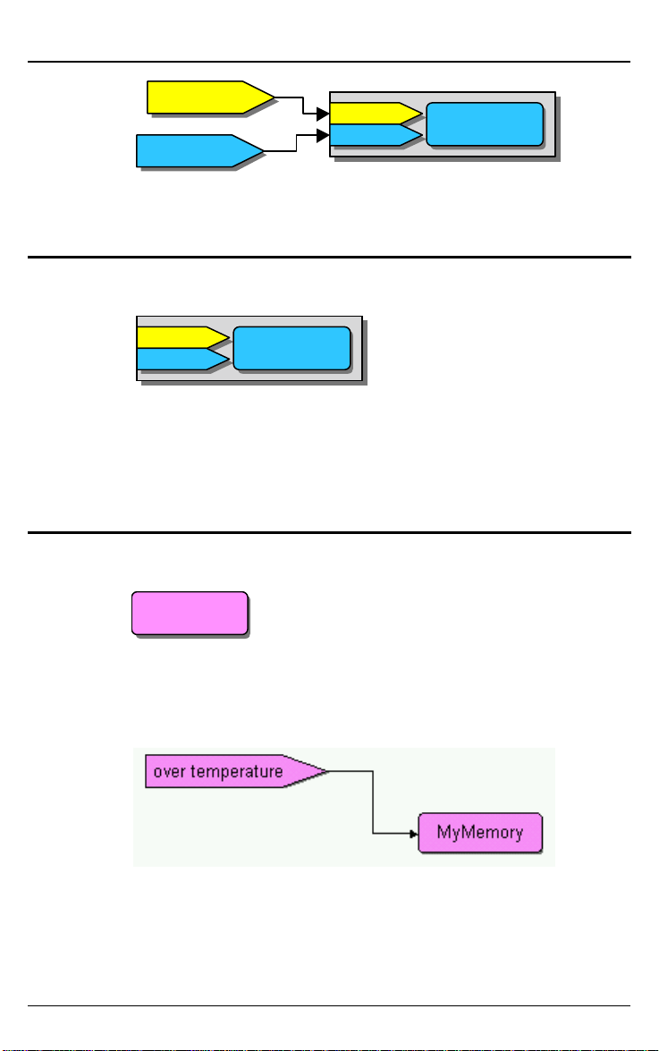
Page/Execute/on binary memory
MyMemory
MyMemory
MyMemory
MyMemory
binary value
binary value
=1
=1
Symbol:
Function: This func tion defines that the page will only be executed if the
binary value MyMemory is 1.
www.hiquel.com 39

HIQUEL
HIQUEL SLS-500-Configurator
HIQUELHIQUEL
Page/Execute/on analogue memory
MyMemory
MyMemory
MyMemory
MyMemory
analog value
analog value
=5
=5
Symbol:
Function: This func tion defines that the page will only be executed if the
analogue value MyMemory is 5.
www.hiquel.com 40

HIQUEL
HIQUEL SLS-500-Configurator
HIQUELHIQUEL
Connections
Use the connections to connect the individual objects with
each other. You can add a new connection object by choosing
Line from the menu.
Creation
Symbol:
Data type: Depending on the object, connections c an operate with all data
types.
Function: The line connects the output of an object to the input of
another object. It’s important for the connection that you have
the correct direction of the arrow.
Mind the direction of the arrow
The arrowhead has always to be next to the input of the
following object.
Example:
Wrong!
The connection was created the wrong way, since the
arrowhead points at the output of the digital input. Take a look
at the correct version:
Right!
www.hiquel.com 41

HIQUEL
HIQUEL SLS-500-Configurator
HIQUELHIQUEL
Create connections
When you click on the connec tion objec t, you will see coloured
rectangles on both ends:
If the rectangles are green, the ends are free and are not
linked with an object. Now m ove the cursor to one of the ends
and left-click the arr ow. Hold the mouse key and drag the line
to an object.
You will notice that small blue symbols appear on the object
that you drag the line to and that the line snaps to the nearest
blue symbol. Select a suitable blue symbol and release the
mouse key. The selected symbol turns from green too red.
This is confirmation of a correct connection.
With the yellow symbol you can change the exact position of
the connection:
Correct connections: Click on the connecting line. Both
rectangles must be red:
www.hiquel.com 42

HIQUEL
HIQUEL SLS-500-Configurator
HIQUELHIQUEL
Wrong!
A connection may seem visually to be correct, but if one of the
rectangles is be green the connection has not been made.
Connect the line with the object again:
Right!
Change the style of the line
To change the line style, right-click the connection line and the
following menu will appear:
Choose from, straight Connec tor (def ault), Elbow Connector or
Curved Connector.
www.hiquel.com 43

HIQUEL
HIQUEL SLS-500-Configurator
HIQUELHIQUEL
Data types of SLS-500Configurator
SLS-500-CONFIGURATOR supports three different data
types:
Bit data
This data type can save exactly 1 Bit or the information 0 or 1.
Examples for bit data are digital inputs or outputs or status
markers.
Analogue data
This data type has the ability to process signed analogue
values to three decimal places. The maximum numerical range
is –2147483.647 to +2147483.648.
Examples for analogue data ar e analogue inputs or analogue
outputs.
Text data
This data type can save text messages. Depending on the
destination system, character strings with different lengths are
supported. Maximum 20 characters per text.
Examples for text data are messages for a display or serial
communication objects.
www.hiquel.com 44

HIQUEL
HIQUEL SLS-500-Configurator
HIQUELHIQUEL
Constants of SLS-500-Configurator
Constants define a fixed value. You can set constants for
every data type of SLS-500-Configurator:
Using several constants with the same value, a „constant
name“ can be predefined and jointly changed.
Binary constants
Binary constants define a value of 0 or 1. Choose from the
SLS-500-Configurator – menu bar the command
Flow/Constants. You will get to the following dialogue:
Now choose binary constant 0 and confirm your choice with
OK.
The active programming page will insert the following symbol:
www.hiquel.com 45

HIQUEL
HIQUEL SLS-500-Configurator
HIQUELHIQUEL
const 0
const 0
If you choose binary constant 1 the following symbol will be
inserted:
const 1
const 1
Define a name for a constant:
Using a named constant:
A normal binary constant is added, the name is adjusted to the
definition. This c onstant represents the binary state 0 or 1 and
can be used as often as desired.
or
www.hiquel.com 46

HIQUEL
HIQUEL SLS-500-Configurator
HIQUELHIQUEL
Analogue constants
Analogue constants define an analogue value. Choose
Flow/Constants and the following dialogue will occur:
Choose Analogue constant and set a fixed value for the new
constant in the field Analogue constant value. Then confirm
with OK.
The following symbol will be inserted:
14.567
14.567
For negative constants:
-345.56
-345.56
www.hiquel.com 47

HIQUEL
HIQUEL SLS-500-Configurator
HIQUELHIQUEL
Also hexadecimal constants will be processed. Write
hexadecimals as follows: starting character is 0x, a c haracter
string follows consis ting of 0.9 or A.F or a..f . You can use a dot
as a visual cut- off signal between the characters as often as
you want. Example: 0xFF.A0. Hexadecimal constants will be
processed as 32-Bit values:
0xff88
0xff88
In addition binary constants are supported. Binary constants
start with a % character. A binary number 0 or 1 follows. You
can use dots as visual cut-off signals.
Examples: %0 or %1
%1111.0101.0000
Define a name for a constant:
Using a named constant:
An analogue constant is added, the name is equal to the
definition. This constant represents the analogue value 43,5
and can be used as often as desired.
www.hiquel.com 48

HIQUEL
HIQUEL SLS-500-Configurator
HIQUELHIQUEL
Text constants
Text constants define fixed character strings. Choose
Flow/Constants and type the following into the text fields of the
dialogue:
After clicking OK the following symbol will occur:
www.hiquel.com 49

HIQUEL
HIQUEL SLS-500-Configurator
HIQUELHIQUEL
INFO To change the value of a c onstant afterwards, click the text of
the symbol and edit the text!
Define a name for a constant:
Using a named constant:
A normal text constant is added, the name is equal to the
definition. This constant repr esents the text „MyText“ and can
be used as often as desired.
www.hiquel.com 50

HIQUEL
HIQUEL SLS-500-Configurator
HIQUELHIQUEL
Special flags
SLS-500-Configurator has a series of special flags, which
display special signals. To insert a special flag choose
Flow/Special flags. Select the desired flag and click OK.
Special flag: START
START
Symbol:
Data type: Bit
Function: This flag has the value 1only during the first program cycle.
START
Otherwise this bit is always 0. Use this flag for example to
initialise values.
Special flag: every 1ms
1ms
Symbol:
Data type: Bit
www.hiquel.com 51
1ms

HIQUEL
HIQUEL SLS-500-Configurator
HIQUELHIQUEL
Function: This flag is not available on every SLS-500 Master-Controller.
The flag has the value 1 for one program cycle at intervals of
1mS. Otherwise the flag is always 0. Use this flag for exam ple
with signal time measuring.
Special flag: every 10ms
10ms
Symbol:
Data type: Bit
Function: The flag has the value 1 for one program cycle at intervals of
10ms
10mS. Otherwise the flag is always 0. Use this flag for
example with signal time measuring
Special flag: every 100ms
100ms
Symbol:
Data type: Bit
100ms
Function: The flag has the value 1 for one program cycle at intervals of
100mS. Otherwise the flag is always 0. Use this flag for
example with signal time measuring.
Special flag: Clock every second
Second
Symbol:
Data type: Bit
Function: an integrated real tim e clock creates this f lag. The flag returns
www.hiquel.com 52
Second
the value 1 every second for exactly one cycle, otherwise it is
0. Use this flag for a flasher signal for example

HIQUEL
HIQUEL SLS-500-Configurator
HIQUELHIQUEL
Special flag: Clock every minute
Minute
Symbol:
Data type: Bit
Function: an integrated real tim e clock creates this f lag. The flag returns
Minute
the value 1 every minute for exactly one cycle, otherwise it is 0.
Special flag: Clock every hour
Hour
Symbol:
Data type: Bit
Function: an integrated real tim e clock creates this f lag. The flag returns
Hour
the value 1 every hour for exactly one cycle, otherwise it is 0.
Special flag: Clock every day
Day
Symbol:
Data type: Bit
Function: an integrated real tim e clock creates this f lag. The flag returns
Day
the value 1 every day at 00:00:00 for exactly one cycle,
otherwise it is 0.
Special flag: Clock every week
Week
Symbol:
Data type: Bit
Function: an integrated real tim e c lock creates this f lag. The flag returns
www.hiquel.com 53
Week
the value 1 every week on Sundays at exactly 00:00:00 for one
cycle, otherwise it is always 0.

HIQUEL
HIQUEL SLS-500-Configurator
HIQUELHIQUEL
Special flag: Clock every month
Month
Symbol:
Data type: Bit
Function: an integrated real tim e clock creates this f lag. The flag returns
Month
the value 1 on the first of every month at exactly 00:00:00 for
one cycle, otherwise it is always 0.
Special flag: Clock every year
Year
Symbol:
Data type: Bit
Function: an integrated real tim e c lock creates this f lag. The flag returns
Yea r
the value 1 every year exactly on the 1st of January at
00:00:00 for one cycle, otherwise it is always 0.
www.hiquel.com 54

HIQUEL
HIQUEL SLS-500-Configurator
HIQUELHIQUEL
Memories
Use the memory spaces to store values of one of the three
data types. These values can be reloaded any time at another
place within the program to continue processing.
Every memory has a name.
INFO You can define the same name for a binary memory and an
analogue memory the graphic colour tells you the difference.
However take care which memory you are actually accessing!
Choose Flow/Memories from the menu, you can select the
following memories:
www.hiquel.com 55

HIQUEL
HIQUEL SLS-500-Configurator
HIQUELHIQUEL
Bit memory
MyMemory
Symbol:
Data type: Bit
Function: Bit memory saves one Bit and transmits it.
MyMemory
const 1
const 1
Examples:
The constant value 1 will be transmitted to MyMemory.
L1.DI1
L1.DI1
The current value of digital input L1.DI1 will be saved to the
1stMemory and also to the 2ndMemory.
MyMemory
MyMemory
The active value of MyMemory will be transmitted to digital
output L1.DO1.
SET bit memory
SET
SET
MyMemory
Symbol:
Data type: Bit
MyMemory
MyMemory
MyMemory
1stMemory
1stMemory
2ndMemory
2ndMemory
L1.DO1
L1.DO1
Function: If the input of the bit mem ory receives the value 1, MyMemory
will be set to 1.
RESET bit memory
RESET
RESET
MyMemory
Symbol:
www.hiquel.com 56
MyMemory

HIQUEL
HIQUEL SLS-500-Configurator
HIQUELHIQUEL
Data type: Bit
Function: If the input of the bit mem ory gets the value 1, MyMemory will
be reset to 0.
L1.DI1
L1.DI1
SET
SET
MyMemory
MyMemory
RESET
RESET
MyMemory
MyMemory
L1.DO1
L1.DO1
Example: (see above)
If digital input L1.DI1 is activated the variable of MyMemory will
be set to 1. This status of MyMemory stays active until the
input L1.DI2 is activated. MyMemor y will then be set to 0. The
status of digital output L1.DO1 will be on when MyMemory is 1
and off when MyMemory is 0.
L1.DI2
L1.DI2
MyMemory
MyMemory
TOGGLE bit memory
TOGGLE
TOGGLE
MyMemory
Symbol:
Data type: Bit
Function: If the input of the bit memory is the value 1, the current content
Examples:
www.hiquel.com 57
MyMemory
of MyMemory will be inverted.

HIQUEL
HIQUEL SLS-500-Configurator
HIQUELHIQUEL
TOGGLE
Second
Second
MyMemory
MyMemory
The value of MyMemory is inverted every second. Digital
output L1.DO1 flashes every second.
TOGGLE
MyMemory
MyMemory
L1.DO1
L1.DO1
Analogue memory
MyMemory
Symbol:
Data type: Analogue
Function: The analogue me mory is able to store an analogue value and
Examples:
MyMemory
to transmit it.
27.35
27.35
MyMemory
MyMemory
The constant value 27.35 is transmitted to the analogue
memory MyMemory.
The current value of analogue input L1.AI1 is transferred to
MyMemory. Also the value of MyMemory will be transmitted to
analogue output R1.AO1.
www.hiquel.com 58

HIQUEL
HIQUEL SLS-500-Configurator
HIQUELHIQUEL
L1.AI1
L1.AI1
MyMemory
MyMemory
MyMemory
MyMemory
/
/
2
2
The current value of analogue input L1.AI1 would be
transmitted to MyMemory. Then the current value will be
divided by 2 and transferred to analogue output R1.AO1.
R1.AO1
R1.AO1
IF rising edge SET analogue memory
In
In
In
In
Symbol:
Value
Value
Value
Value
MyMemory
MyMemory
MyMemory
MyMemory
Data type: In Bit
Value Analogue
Function: When digital input In reads a rising edge, the value of input
Value will be saved to MyMemory.
Example:
L1.DI4
L1.DI4
In
In
In
In
Value
Value
Value
L1.AI1
L1.AI1
With every rising edge of digital input L1.DI4, the exis ting value
of analogue input L1.AI1 will be saved to MyMemory.
www.hiquel.com 59
Value
MyMemory
MyMemory
MyMemory
MyMemory

HIQUEL
HIQUEL SLS-500-Configurator
HIQUELHIQUEL
IF falling edge SET analogue memory
In
In
In
In
Value
Value
Value
Symbol:
Data type: In Bit
Value Analogue
Function: W hen digital input In r eads a falling edge, the ex isting value of
Value
input Value will be saved to MyMemory.
MyMemory
MyMemory
MyMemory
MyMemory
IF both edges SET analogue memory
In
In
In
In
Value
Value
Value
Symbol:
Data type: In Bit
Value Analogue
Value
MyMemory
MyMemory
MyMemory
MyMemory
Function: W hen digital input In reads a ris ing or a falling edge, the value
of input Value
will be saved to MyMemory.
IF permanent high SET analogue memory
In==1
In==1
In==1
In==1
Value
Value
Value
Symbol:
Data type: In Bit
Value Analogue
Function: All the time digital input In reads the value 1, the value of input
Example:
www.hiquel.com 60
Value
Value will be saved to MyMemory.
MyMemory
MyMemory
MyMemory
MyMemory
HIQUEL
HIQUEL SLS-500-Configurator
HIQUELHIQUEL
START
START
-2.5
-2.5
Just at program start up, the value –2.5 will be saved to the
variable MyMemory.
In==1
In==1
In==1
In==1
Value
Value
Value
Value
MyMemory
MyMemory
MyMemory
MyMemory
IF permanent low SET anal ogue memor y
In==0
In==0
In==0
In==0
Value
Value
Value
Symbol:
Data type: In Bit
Value Analogue
Function: All the time digital input In reads the value 0, the value of input
Value
Value will be saved to MyMemory.
MyMemory
MyMemory
MyMemory
MyMemory
Text memory
MyMemory
Symbol:
Data type: Text
Function: The text memory is able to store a text value and to transmit it.
Examples:
www.hiquel.com 61
MyMemory
The constant value will be saved to the text memory
MyMemory.

HIQUEL
HIQUEL SLS-500-Configurator
HIQUELHIQUEL
The text mem ory MyMemory is loaded with the constant value
„Hallo „. After this the constant value „ HIQUEL“ will be added
to the content of MyMemory and saved to 2
result at 2
nd
Memory is „Hallo HIQUEL“
nd
Memory. The
IF rising edge SET text memory
In
In
In
In
Value
Value
Value
Value
Symbol:
Data type: In Bit
MyMemory
MyMemory
MyMemory
MyMemory
Value Text
Function: If digital input In reads a rising edge, the value of input Value
will be transmitted to MyMemory.
IF falling edge SET text memory
In
In
In
In
Value
Value
Value
Value
Symbol:
Data type: In Bit
Value Text
Function: If digital input In reads a f alling edge, the value of input Value
will be transmitted to MyMemory.
www.hiquel.com 62
MyMemory
MyMemory
MyMemory
MyMemory

HIQUEL
HIQUEL SLS-500-Configurator
HIQUELHIQUEL
IF both edges SET text memory
In
In
In
In
Symbol:
Value
Value
Value
Value
MyMemory
MyMemory
MyMemory
MyMemory
Data type: In Bit
Value Text
Function: If digital input In reads a rising or falling edge, the value of
input Value will be transmitted to MyMemory.
IF permanent high SET text memory
In==1
In==1
In==1
In==1
Value
Value
Value
Value
Symbol:
Data type: In Bit
Value Text
MyMemory
MyMemory
MyMemory
MyMemory
Function: As long as digital input In reads the value 1, the value of input
Value will be transmitted to MyMemory.
START
Example:
START
Now
Now
In==1
In==1
In==1
In==1
Value
Value
Value
Value
MyMemory
MyMemory
MyMemory
MyMemory
The value „Now“ will only be saved to the variable MyMemory
at program start up.
IF permanent low SET text memory
In==0
In==0
In==0
In==0
Value
Value
Value
Value
Symbol:
www.hiquel.com 63
MyMemory
MyMemory
MyMemory
MyMemory

HIQUEL
HIQUEL SLS-500-Configurator
HIQUELHIQUEL
Data type: In Bit
Value Text
Function: As long as digital input In reads the value 0, the value of input
will be saved to MyMemory.
Value
www.hiquel.com 64

HIQUEL
HIQUEL SLS-500-Configurator
HIQUELHIQUEL
Binary operators
There are a series of operators available for binary
calculations. Choose Flow/Bit handling from the menu and
select one of the following operators:
Binary operator: Binary AND
&
Symbol:
&
Data type: In1,In2 Bit
Out Bit
Function: T h is f unc tion c alc ulates the AND- c onnection by using two input
signals and delivers the result to the output.
In1 In2 Out
0 0 0
0 1 0
1 0 0
1 1 1
www.hiquel.com 65

HIQUEL
HIQUEL SLS-500-Configurator
HIQUELHIQUEL
L1.DI1
L1.DI1
&
&
L1.DO1
L1.DO1
L1.DI2
L1.DI2
Example:
Digital output L1.DO1 is active, only if both digital inputs L1.DI1
and L1.DI2 are simultaneously active.
Binary operator: Binary OR
|
Symbol:
Data type: In1,In2 Bit
Out Bit
Function: This function calculates the O R-connection by using two input
|
signals and delivers the result to the output.
In1 In2 Out
0 0 0
0 1 1
1 0 1
1 1 1
L1.DI1
L1.DI1
|
|
L1.DO1
L1.DO1
L1.DI2
L1.DI2
Example:
www.hiquel.com 66

HIQUEL
HIQUEL SLS-500-Configurator
HIQUELHIQUEL
The digital output L1.DO1 is active as soon as one of the two
digital inputs L1.DI1 and L1.DI2 are active. If both are active
the digital output will be active too.
Binary operator: Binary EXCLUSIVE OR
^
Symbol:
Data type: In1,In2 Bit
Out Bit
Function: This function calculates the EXCLUSIVE OR-connection by
^
using two input signals and delivers the result to the output.
In1 In2 Out
0 0 0
0 1 1
1 0 1
1 1 0
L1.DI1
L1.DI1
^
^
L1.DO1
L1.DO1
L1.DI2
L1.DI2
Example:
Digital output L1.DO1 is active, as long as one of the two
digital inputs L1.DI1 and L1.DI2 is active. If both are
simultaneously active, the digital output will not be active.
www.hiquel.com 67

HIQUEL
HIQUEL SLS-500-Configurator
HIQUELHIQUEL
Binary operator: Binary NEGATION
~
Symbol:
Data type: In Bit
Out Bit
Function: The current input value will be inverted.
Example:
Digital output L1.DO1 always has the opposite signal status of
~
In Out
0 1
1 0
L1.DI1
L1.DI1
~
digital input L1.DI1.
~
L1.DO1
L1.DO1
Binary operator: Rising edge
Symbol:
Data type: In Bit
Out Bit
Function: If the input signal has a rising edge, this function is high for
Example:
www.hiquel.com 68
exactly one cycle.
In
Out

HIQUEL
HIQUEL SLS-500-Configurator
HIQUELHIQUEL
L1.DI1
L1.DI1
L1.DO1
L1.DO1
If digital input L1.DI1 reads a rising edge, digital output L1.DO1
will be high for exactly one cycle.
Binary operator: falling edge
Symbol:
Data type: In Bit
Out Bit
Function: If the input signal reads a falling edge, the func tion is high for
exactly one cycle.
In
Out
Binary operator: Both edges
Symbol:
Data type: In Bit
Out Bit
Function: If the input signal reads a rising or a falling edge, the function
www.hiquel.com 69
is high for exactly one cycle.
In
Out

HIQUEL
HIQUEL SLS-500-Configurator
HIQUELHIQUEL
Binary operator: Split
Symbol:
Data type: In Bit
Out1,Out2 Bit
Function: This function s plits the data into two paths. Both of the outputs
Example:
have the same signal as the input.
The input signal L1.DI1 will be simultaneously transmitted to
outputs L1.DO1 and L1.DO2.
L1.DI1
L1.DI1
L1.DO2
L1.DO2
L1.DO1
L1.DO1
www.hiquel.com 70

HIQUEL
HIQUEL SLS-500-Configurator
HIQUELHIQUEL
Analogue operators
The following operators are available for processing the
analogue signals. Choose Flow/Analogue handling from the
menu:
Analogue operator: Addition
+
Symbol:
Data type: In1,In2 Analogue
Out Analogue
Function: This function calculates the sum of the two analogue signals
www.hiquel.com 71
+
In1 and In2 and delivers the result to output Out.

HIQUEL
HIQUEL SLS-500-Configurator
HIQUELHIQUEL
Example:
L1.AI1
L1.AI1
+
+
MyMemory
50.0
50.0
The value 50.0 will be added to the current value of analogue
input L1.AI1. The result will be saved to MyMemory.
MyMemory
Analogue operator: Subtraction
-
Symbol:
Data type: In1,In2 Analogue
Out Analogue
-
Function: This function subtracts the value of one analogue input from
another analogue output and saves the result to output Out.
Example:
L1.AI1
L1.AI1
-
-
MyMemory
L1.AI2
L1.AI2
Analogue value L1.AI2 is subtracted from analogue value
L1.Al1. The result will be saved to MyMemory.
www.hiquel.com 72
MyMemory

HIQUEL
HIQUEL SLS-500-Configurator
HIQUELHIQUEL
Analogue operator: Multiplication
*
Symbol:
Data type: In1,In2 Analogue
Out Analogue
Function: This function multiplies the two analogue signals In1 and In2
Example:
*
and delivers the result to output Out.
R1.POTI1
R1.POTI1
*
*
MyMemory
0.1
0.1
The current potentiom eter value R1.POT I1 is multiplied by the
factor 0.1. T he result will be saved to MyMemory. In this way
you can get a potentiometer value between 0 and 10.
MyMemory
Analogue operator: Division
/
Symbol:
Data type: In1,In2 Analogue
Out Analogue
Function: This function divides analogue signal In1 by In2 and delivers
www.hiquel.com 73
/
the result to output Out.

HIQUEL
HIQUEL SLS-500-Configurator
HIQUELHIQUEL
Example:
R1.POTI1
R1.POTI1
/
/
MyMemory
10
10
The current potentiometer value R1.POTI1 is divided by 10.
The result will be saved to MyMemory. In this way you can get
a potentiometer value between 0 and 10.
MyMemory
Analogue operator: Modulo (read part of a value)
%
Symbol:
Data type: In1,In2 Analogue
Out Analogue
%
Function: T his function transf ers part of the analogue value (In1 divided
by ln2) to output MyMemory.
Example:
1234.5678
www.hiquel.com 74
L1.AI1
L1.AI1
%
%
MyMemory
100
100
The current analogue value of analogue input L1.AI1 is
calculated with modulo 100. The result will be delivered to
MyMemory.
MyMemory
34.5678

HIQUEL
HIQUEL SLS-500-Configurator
HIQUELHIQUEL
Analogue operator: Shift left
<<
Symbol:
Data type: In1,In2 Analogue
Out Analogue
Function: This function s hifts the bits of input In1 to the left by In2 bits
Example:
<<
and delivers the result to output Out.
The current analogue value of analogue input L1.AI1 will be
shifted by 3 bits to the left. In this way the current value will be
multiplied by 8. The result will be saved to MyMemory.
L1.AI1
L1.AI1
3
3
<<
<<
MyMemory
MyMemory
Analogue operator: Shift right
>>
Symbol:
Data type: In1,In2 Analogue
Out Analogue
Function: T his function shifts the bits of input In1 to the right by In2 bits
www.hiquel.com 75
>>
and delivers the result to output Out.

HIQUEL
HIQUEL SLS-500-Configurator
HIQUELHIQUEL
Example:
L1.AI1
L1.AI1
>>
>>
MyMemory
1
The current analogue value of analogue input L1.AI1 would be
shifted by 1 bit to the right. In this way the current value will be
divided by two. The result will be saved to MyMemory.
1
MyMemory
Analogue operator: Greater than
>
Symbol:
Data type: In1,In2 Analogue
Out Bit
>
Function: This f unction c om pares the two analogue input signals In1 and
In2. If In1 is greater than In2, the output will deliver a binary 1,
otherwise a 0 will be transmitted.
Example:
L1.AI1
L1.AI1
>
>
L1.DO1
50.0
50.0
If analogue input L1.AI1 is greater than 50.0, digital output
L1.DO1 is activated.
www.hiquel.com 76
L1.DO1

HIQUEL
HIQUEL SLS-500-Configurator
HIQUELHIQUEL
Analogue operator: Greater or equal
>=
Symbol:
Data type: In1,In2 Analogue
Out Bit
Function: T his f unc tion c ompares the analogue input signals In1 and In2.
Example:
>=
If In1 is greater than or equal to In2, the output will deliver a
binary 1, otherwise a 0 will be transmitted.
If analogue input L1.AI1 is greater than or equal to 50.0, digital
output L1.DO1 will be active.
L1.AI1
L1.AI1
50.0
50.0
>=
>=
L1.DO1
L1.DO1
Analogue operator: Equal
=
Symbol:
Data type: In1,In2 Analogue
Out Bit
Function: T his f unc tion c ompares the analogue input signals In1 and In2.
www.hiquel.com 77
=
If In1 is equal to In2, the output will deliver a binary 1,
otherwise a 0 will be transmitted.

HIQUEL
HIQUEL SLS-500-Configurator
HIQUELHIQUEL
Example:
L1.AI1
L1.AI1
=
=
L1.DO1
50.0
50.0
If analogue input L1.AI1 has the value 50.000, the analogue
output L1.DO1 will be activated.
L1.DO1
Analogue operator: Not equal
!=
Symbol:
Data type: In1,In2 Analogue
Out Bit
!=
Function: T his f unc tion c ompares the analogue input signals In1 and In2.
If In1 is not equal to In2, the output delivers a binary 1;
otherwise a 0 will be transmitted.
Example:
L1.AI1
L1.AI1
!=
!=
L1.DO1
50.0
50.0
If analogue input L1.AI1 does not have the value 50.000, digital
output L1.DO1 will be activated.
www.hiquel.com 78
L1.DO1

HIQUEL
HIQUEL SLS-500-Configurator
HIQUELHIQUEL
Analogue operator: Less or equal
<=
Symbol:
Data type: In1,In2 Analogue
Out Bit
Function: T his f unc tion c ompares the analogue input signals In1 and In2.
Example:
<=
If In1 is less than or equal to In2, the output delivers a binary 1,
otherwise a 0 will be transmitted.
If analogue input L1.AI1 has the value less than or equal to
50.000, digital output L1.DO1 will be activated.
L1.AI1
L1.AI1
50.0
50.0
<=
<=
L1.DO1
L1.DO1
Analogue operator: Less
<
Symbol:
Data type: In1,In2 Analogue
Out Bit
Function: T his f unc tion c ompares the analogue input signals In1 and In2.
www.hiquel.com 79
<
If In1 is less than ln2, the output delivers a binar y 1; otherwise
a 0 will be transmitted.

HIQUEL
HIQUEL SLS-500-Configurator
HIQUELHIQUEL
Example:
L1.AI1
L1.AI1
<
<
L1.DO1
50.0
50.0
If analogue input L1.AI1 has a value less than 50.000, digital
output L1.DO1 will be activated.
L1.DO1
Analogue operator: Logical AND
&&
Symbol:
Data type: In1,In2 Analogue
Out Analogue
&&
Function: T his f unc tion c ompares the analogue input signals In1 and In2.
If In1 is not equal to 0 and ln2 is not equal to 0, the output Out
delivers a value that is unequal to 0 too. Otherwise the value 0
will be returned.
Example:
L1.AI1
L1.AI1
&&
&&
MyMemory
L1.AI2
L1.AI2
If analogue inputs L1.AI1 and L1.AI2 are not equal to 0, the
variable MyMemory will be unequal to 0 too.
www.hiquel.com 80
MyMemory

HIQUEL
HIQUEL SLS-500-Configurator
HIQUELHIQUEL
Analogue operator: Logical OR
||
Symbol:
Data type: In1,In2 Analogue
Out Analogue
Function: T his f unc tion c ompares the analogue input signals In1 and In2.
Example:
||
If In1 is not equal to 0 or ln2 is not equal to 0, the output Out
delivers a value that is unequal 0 too. Otherwise the value 0
will be returned.
L1.AI1
L1.AI1
||
||
MyMemory
L1.AI2
L1.AI2
Only if at least one of the two analogue inputs L1.AI1 and
L1.AI2 is unequal 0, the variable MyMemory will be unequal 0
too.
MyMemory
Analogue operator: Logical NOT
!
Symbol:
Data type: In Analogue
Out Analogue
Function: This function measures the analogue input signal In. If the
www.hiquel.com 81
!
input In has value 0, at output Out a value unequal 0 will be
returned. If the input is unequal to 0, the value 0 will be
returned.

HIQUEL
HIQUEL SLS-500-Configurator
HIQUELHIQUEL
Example:
L1.AI1
L1.AI1
!
!
MyMemory
If analogue input L1.AI1 has exactly the value 0, the variable
MyMemory will be unequal 0.
MyMemory
Analogue operator: Split
Symbol:
Data type: In Analogue
Out1,Out2 Analogue
Function: This function splits the input data into two paths. Both of the
outputs will have the same signal as the input.
Example:
L1.AI1
L1.AI1
MyMemory
MyMemory
R1.AO1
R1.AO1
The input signal L1.AI1 will be simultaneously transmitted to
analogue output L1.AO1 and to MyMemory.
www.hiquel.com 82

HIQUEL
HIQUEL SLS-500-Configurator
HIQUELHIQUEL
Text operators
The following operators are available for processing texts. Choose
Flow/Text handling from the menu to get to the following dialogue:
Text operator: Combine text
+
Symbol:
Data type: In1,In2 Text
Out Text
Function: This f unction com bines the texts In1 and In2 to a new text and
Example:
www.hiquel.com 83
+
delivers it to output Out.
Hallo
Hallo
+
+
MyMemory
Welt
Welt
Both text parts „Hallo“ and „Welt“ will be assem bled and s aved
to MyMemory as Hallo Welt (Hello world)
MyMemory

HIQUEL
HIQUEL SLS-500-Configurator
HIQUELHIQUEL
Text operator: Greater
>
Symbol:
Data type: In1,In2 Text
Out Bit
Function: T his function com pares the texts In1 and In2. If In1 is greater
Example:
>
than In2, a binary 1 will be delivered to the output. Otherwise a
0 will be transmitted.
Alpha
Alpha
>
>
L1.DO1
Beta
Beta
As Alpha is not greater than Beta, digital output L1.DO1 is not
active.
L1.DO1
Text operator: Greater or equal
>=
Symbol:
Data type: In1,In2 Text
Out Bit
Function: T his function com pares the texts In1 and In2. If In1 is greater
Example:
www.hiquel.com 84
>=
than or equal that In2, a binary 1 will be delivered to the output.
Otherwise a 0 will be transmitted.

HIQUEL
HIQUEL SLS-500-Configurator
HIQUELHIQUEL
Alpha
Alpha
>=
>=
L1.DO1
Beta
Beta
As Alpha is not greater than or equal to Beta, digital output
L1.DO1 is not active.
L1.DO1
Text operator: Equal
=
Symbol:
Data type: In1,In2 Text
Out Bit
Function: This func tion compares the texts In1 and In2. If In1 is equal to
=
In2, a binary 1 will be delivered to the output. Otherwise a 0 will
be transmitted.
Example:
Alpha
Alpha
=
=
L1.DO1
Beta
Beta
As Alpha is not equal to Beta, digital output L1.DO1 is not
active.
L1.DO1
Text operator: Not equal
!=
Symbol:
www.hiquel.com 85
!=

HIQUEL
HIQUEL SLS-500-Configurator
HIQUELHIQUEL
Data type: In1,In2 Text
Out Bit
Function: This function compares the texts In1 and In2. If In1 is not equal
to In2, a binary 1 will be delivered to the output. Otherwise a 0
will be transmitted.
Example:
Alpha
Alpha
!=
!=
L1.DO1
Beta
Beta
As Alpha is not equal to Beta, digital output L1.DO1 is active.
L1.DO1
Text operator: Less or equal
<=
Symbol:
<=
Data type: In1,In2 Text
Out Bit
Function: T his f unc tion c ompares the texts In1 and In2. If In1 is less than
or equal to In2, a binary 1 will be delivered to the output.
Otherwise a 0 will be transmitted.
Example:
www.hiquel.com 86

HIQUEL
HIQUEL SLS-500-Configurator
HIQUELHIQUEL
Alpha
Alpha
<=
<=
L1.DO1
Beta
Beta
As Alpha is less than (or equal to) Beta, digital output L1.DO1
is active.
L1.DO1
Text operator: Less
<
Symbol:
Data type: In1,In2 Text
Out Bit
Function: T his f unc tion c ompares the texts In1 and In2. If In1 is less than
<
In2, a binary 1 will be delivered to the output. Otherwise a 0 will
be transmitted.
Example:
Alpha
Alpha
<
<
L1.DO1
Beta
Beta
As Alpha is less than Beta, digital output L1.DO1 is active.
L1.DO1
Text operator: Split
Symbol:
Data type: In Text
www.hiquel.com 87

HIQUEL
HIQUEL SLS-500-Configurator
HIQUELHIQUEL
Out1,Out2 Text
Function: This function splits the tex t into two paths. Both of the outputs
have the same signal as the input.
Example:
Alpha
Alpha
1stMemory
The input signal L1.AI1 will be simultaneously delivered to
analogue output L1.AO1 and to MyMemory.
1stMemory
2ndMemory
2ndMemory
Text operator: Sub String
In
In
In
In
Start
Start
Start
Start
Length
Length
Length
Symbol:
Data type: In Text
Out Text
Start Analogue
Length Analogue
Function: T his function delivers to output Out parts of character strings.
Length
The first letter of the str ing is defined in start and the number
of characters is defined in length. The Start index starts
counting with 0 therefore the first character of a full string is
character 0.
TEXT
TEXT
TEXT
TEXT
SubString
SubString
SubString
SubString
Out
Out
Out
Out
Example:
www.hiquel.com 88

HIQUEL
HIQUEL SLS-500-Configurator
HIQUELHIQUEL
Hallo Welt
Hallo Welt
In
In
In
In
Start
Start
Start
Start
Length
Length
Length
Length
2
2
3
3
TEXT
TEXT
TEXT
TEXT
SubString
SubString
SubString
SubString
The text string llo will be saved to MyMemory!
Text operator: Left String
In
In
In
In
Length
Length
Length
Length
Symbol:
Data type: In Text
Out Text
Length Analogue
TEXT
TEXT
TEXT
TEXT
LeftString
LeftString
LeftString
LeftString
Out
Out
Out
Out
Out
Out
Out
Out
MyMemory
MyMemory
Function: This function delivers to output Out only the first X Length
character of input In.
Example:
www.hiquel.com 89

HIQUEL
HIQUEL SLS-500-Configurator
HIQUELHIQUEL
Hal l o Welt
Hallo Welt
In
In
In
In
Length
Length
Length
Length
5
5
TEXT
TEXT
TEXT
TEXT
LeftString
LeftString
LeftString
LeftString
Out
Out
Out
Out
MyMemory
MyMemory
The text string Hallo will be saved to the variable MyMemory!
Text operator: Right String
In
In
In
In
Length
Length
Length
Length
TEXT
TEXT
TEXT
TEXT
RightString
RightString
RightString
RightString
Symbol:
Data type: In Text
Out Text
Length Analogue
Function: Th is function delivers to output out only X Length characters
of input In counting from the last character of the string.
Out
Out
Out
Out
Example:
Hal l o Welt
Hallo Welt
In
In
In
In
Length
Length
Length
Length
4
4
TEXT
TEXT
TEXT
TEXT
RightString
RightString
RightString
RightString
Out
Out
Out
Out
MyMemory
MyMemory
The text string Welt will be saved to MyMemory!
www.hiquel.com 90

HIQUEL
HIQUEL SLS-500-Configurator
HIQUELHIQUEL
Text operator: String Length
Symbol:
In
In
In
In
TEXT
TEXT
TEXT
TEXT
StringLength
StringLength
StringLe ngth
StringLe ngth
Out
Out
Out
Out
Data type: In Text
Out Analogue
Function: This function delivers the num ber of character s included in the
text string of input ln to output Out.
Example:
Hallo Welt
Hallo W elt
In
In
In
In
TEXT
TEXT
TEXT
TEXT
StringLength
StringLength
StringLength
StringLength
Out
Out
Out
Out
MyMemory
MyMemory
The length of the text string Hallo Welt will be saved to
MyMemory. These are exactly 10 characters!
www.hiquel.com 91

HIQUEL
HIQUEL SLS-500-Configurator
HIQUELHIQUEL
Counter
This chapter deals with the integrated counters.
To insert a counter choose Flow/Counter. The following
dialogue will appear:
Counter: Count Up
CO UNT UP
CO UNT UP
CO UNT UP
CO UNT UP
In
In
In
In
Value
Value
Value
Symbol:
Data type: In Bit
Value Analogue
Function: When input ln reads a ris ing edge, this function adds the value
www.hiquel.com 92
Value
Value to the value of the analogue mem ory MyCounter. The
use of Input Value is optional. If the input value remains
unused, the value 1.000 will be added.
MyCounter
MyCounter
MyCounter
MyCounter

HIQUEL
HIQUEL SLS-500-Configurator
HIQUELHIQUEL
L1.DI1
L1.DI1
CO UNT UP
CO UNT UP
CO UNT UP
CO UNT UP
In
In
In
In
Example:
Value
Value
Value
Value
MyCounter
MyCounter
MyCounter
MyCounter
Every time digital input L1.DI1 detects a rising edge, the
analogue memory MyCounter will be increased by one.
L1.DI2
2.45
2.45
L1.DI2
In
In
Value
Value
In
In
Value
Value
CO UNT UP
CO UNT UP
CO UNT UP
CO UNT UP
MyCounter
MyCounter
MyCounter
MyCounter
Every time digital input L1.DI2 detects a rising edge, the value
2.45 will be added to MyCounter.
Counter: Count Down
CO UNT DOW N
CO UNT DOW N
CO UNT DOW N
CO UNT DOW N
In
In
In
In
Symbol:
Value
Value
Value
Value
MyCounter
MyCounter
MyCounter
MyCounter
Data type: In Bit
Value Analogue
Function: When input ln reads a rising edge, this f unction subtracts the
value Value from the value of the analogue memory
MyCounter. The use of Input Value is optional. If the input
value remains unused, the value 1.000 will be subtracted.
www.hiquel.com 93

HIQUEL
HIQUEL SLS-500-Configurator
HIQUELHIQUEL
Example:
L1.DI1
L1.DI1
CO UNT DO WN
CO UNT DO WN
CO UNT DOWN
CO UNT DOWN
In
In
In
In
Value
Value
Value
Value
MyCounter
MyCounter
MyCounter
MyCounter
Every time digital input L1.DI1 detects a rising edge, the
analogue memory MyCounter will be reduced by one.
L1.DI2
2.45
2.45
L1.DI2
CO UNT DOWN
CO UNT DOWN
CO UNT DO WN
CO UNT DO WN
In
In
In
In
Value
Value
Value
Value
MyCounter
MyCounter
MyCounter
MyCounter
Every time digital input L1.DI2 detects a rising edge, the value
2.45 will be subtracted from MyCounter.
Counter: Count Set
COUNT SET
COUNT SET
COUNT S ET
COUNT S ET
In
In
In
In
Value
Value
Value
Value
Symbol:
Data type: In Bit
Value Analogue
Function: If input ln detects a rising edge, the analogue memory
MyCounter will be set to value Value. Input Value is optional. If
it stays unused the value 0.000 will be set.
www.hiquel.com 94
MyCounter
MyCounter
MyCounter
MyCounter

HIQUEL
HIQUEL SLS-500-Configurator
HIQUELHIQUEL
Example:
L1.DI1
L1.DI1
COUNT S ET
COUNT S ET
COUNT SET
COUNT SET
In
In
In
In
Value
Value
Value
Value
MyCounter
MyCounter
MyCounter
MyCounter
Every time digital input L1.DI1 detects a rising edge, the
analogue memory MyCounter will be reset to 0.
L1.DI2
100
100
L1.DI2
In
In
In
In
Value
Value
Value
Value
COUNT S ET
COUNT S ET
CO UNT SET
CO UNT SET
MyCounter
MyCounter
MyCounter
MyCounter
Every time digital input L1.DI2 detects a rising edge, the
analogue memory MyCounter will be set to 100.000.
Counter: Count up with l imit
Symbol:
Data type: In Bit
Value Analogue
Limit Analogue
Function: If input ln detects a rising edge, the value Value will be add to
the analogue memory My Counter. Input Value is optional. If it
stays unused the value 1.000 will be added.
www.hiquel.com 95

HIQUEL
HIQUEL SLS-500-Configurator
HIQUELHIQUEL
The process can be repeated as long as the Limit for the
analogue input is reached. If the Limit stays unused, no limit
will be set.
Example:
Every time a rising edge is detected at digital input L1.DI1 the
analogue memory MyCounter will be increased by one.
With every rising edge at digital input L1.DI2 the value 1 will be
added to MyCounter, as long as MyCounter reaches the value
5.
Counter: Count down with limit
Symbol:
Data type: In Bit
Value Analogue
Limit Analogue
Function: With every rising edge at input ln the value Value will be
subtracted from MyCounter. The input Value is optional.
www.hiquel.com 96

HIQUEL
HIQUEL SLS-500-Configurator
HIQUELHIQUEL
If it stays unused the value 1.000 will be subtracted. The
process can be repeated as long as the Lim it for the analogue
input is reached. If the Limit stays unused, no limit will be set.
Example:
Every time a rising edge is detected at digital input L1.DI1 the
analogue memory MyCounter will be lowered by 1.
With every rising edge at digital input L1.DI2 the value 1 will be
subtracted from MyCounter as long as MyCounter reaches the
value 10.
www.hiquel.com 97

HIQUEL
HIQUEL SLS-500-Configurator
HIQUELHIQUEL
Conversion
This chapter deals with comm ands, which can be used f or the
conversion of data. Choose Flow/Conversion from the menu.
The following dialogue will occur:
Conversion: Binary->Analogue
In
In
In
In
Symbol:
Data type: In Bit
Out Analogue
www.hiquel.com 98
Binary->Analog
Binary->Analog
Binary->Analog
Binary->Analog
0->0.0
0->0.0
0->0.0
0->0.0
1->100.0
1->100.0
1->100.0
1->100.0
Out
Out
Out
Out

HIQUEL
HIQUEL SLS-500-Configurator
HIQUELHIQUEL
Dialogue:
Function: This function converts a binary value to an analogue value. For
this you can select the analogue values, which represent
binary status 0 and 1.
Example:
L1.DI1
L1.DI1
In
In
In
In
Binary->Analog
Binary->Analog
Binary->Analog
Binary->Analog
0->25.0
0->25.0
0->25.0
0->25.0
1->75.0
1->75.0
1->75.0
1->75.0
Out
Out
Out
Out
R1.AO1
R1.AO1
If digital input L1.DI1 receives no signal, analogue output
R1.AO1 is at 25%. If the digital input receives a signal, the
analogue output will be at 75%.
Conversion: Analogue->Binary
In
In
In
In
Analog->Binary
Analog->Binary
Analog->Binary
Analog->Binary
<=50.0->0
<=50.0->0
<=50.0->0
<=50.0->0
>50.0->1
>50.0->1
>50.0->1
>50.0->1
Symbol:
Data type: In Analogue
Out Bit
www.hiquel.com 99
Out
Out
Out
Out

HIQUEL
HIQUEL SLS-500-Configurator
HIQUELHIQUEL
Dialogue:
Function: This function converts an analogue value to a binary value. For
this the analogue value will function by using a threshold. If the
existing analogue value at input ln is below the threshold or
exactly on the threshold value (for example 50.0) , output Out
will deliver the binary value 0. If the input value is above the
threshold, the binary value 1 will be delivered.
Example:
R1.POTI1
R1.POTI1
In
In
In
In
Analog->Binary
Analog->Binary
Analog->Binary
Analog->Binary
<=50.0->0
<=50.0->0
<=50.0->0
<=50.0->0
>50.0->1
>50.0->1
>50.0->1
>50.0->1
Out
Out
Out
Out
R1.DO1
R1.DO1
If the value set at potentiometer R1.POT I1 is below or equal
50.0, digital output R1.DO1 will be switched of f. If the value is
higher than 50%, the digital output will be switched on.
www.hiquel.com 100
 Loading...