

Kontrollrelais / Monitoring-relay –
•
4
in-
case – Füllstandsüberwachung / Liquid level monitoring – ICL
in-case
Füllstandsüberwachung /
Liquid level monitoring
ICL
HIQUEL GmbH
Bairisch Kölldorf 266
8344 Bad Gleichenberg
AUSTRIA
Tel.: +43-(0)3159-3001
Fax: +43-(0)3159-3001-4
Email: hiquel@hiquel.com
http://www.hiquel.com
Die veröffentlichten Beiträge in dieser Unterlage sind urheberrechtlich geschützt. Ihre auch nur auszugsweise Vervielfältigung
und Verbreitung ist ausnahmslos nur mit vorheriger schriftlicher
Zustimmung des Herausgebers gestattet. Die HIQUEL GmbH
sowie die Autoren können für eventuell vorhandene Fehler keine
Haftung jeweiliger Art für fehlerhafte Angaben und deren Folgen
übernehmen.
This documentation and the accompanying illustrations are
copyrighted. This manual may not be copied in part or whole in
any form including electronic media without the written consent of
HIQUEL GmbH. The editors and publishers accept no responsibility for any inadvertent omission of entries or for typographical or
other errors herein. Nor can they be held responsible or liable for
consequences arising from any errors herein.
01.02
BESCHREIBUNG / FEATURES
• Überwachung von 1 oder 2 Füllständen
leitender Flüssigkeiten
• Füllen oder Entleeren einstellbar
• Trockenlaufschutz oder Überfüllschutz
einstellbar
• Empfindlichkeit 100Ω bis 100kΩ
• Automatischer oder manueller Reset
wählbar
• Fehlerspeicherfunktion
• 2 Ausgangsrelais mit 1 Wechsler
• LED Anzeige für Versorgungsspan-
nung, Sensoren, Fehler und Status der
Ausgangsrelais
• Gehäusebreite: 22,5mm klemmbar
Monitors 1 or 2 levels of conductive
liquids
• Programmable filling or emptying mode
• Selectable mode for protection against
dry running / overflow
• Adjustable sensitivity 100Ω to 100kΩ
• Automatic or manual reset selectable
• Alarm memory function
• 2 x SPCO output relay
• LED indicator for power supply, sensor
status, failure and status of the output
relays
• 22,5mm DIN rail mount housing
BESTELLDATEN / ORDERING INFORMATION
Artikel / Article Nennspannung / nominal voltage
ICL 24Vac 24Vac 2,5VA / 1W
ICL 115Vac 115Vac 2,5VA / 1W
ICL 230Vac 230Vac 2,5VA / 1W
ICL 400Vac 400Vac 2,5VA / 1W
TECHNISCHE DATEN / SPECIFICATION
Spannungsbereich /
suppl y vo l t a g e va riatio n
Nennspannung / nominal voltage
-20%..+10%
Zulässige Frequenz / frequency range 48 - 63 Hz
Einschaltdauer / duty cycle 100%
Wiederholgenauigkeit / repeat accuracy <1%
Ausgangsstufe /
max. 6A 230V~
output relay specification
Ue/Ie AC-15* 24V/1,5A 115V/1,5A 230V/1,5A
Ue/Ie DC-13* 24V/1A
Lebensdauer / expected life time 2 x 1 Wechsler / 2 x SPCO
Mechanisch / mechanical 10 x 106 Schaltspiele / operations
Elektrisch / electrical 8 x 10
Schaltspiele / operations
Schrauben / screws Pozidrive 1
Anzugsdrehmoment / screw tight. torque 0,6...0,8Nm
Arbeitsbedingungen /
operating conditions
-20 bis +60 C
nicht kondensierend /
non condensing
* EN 60947-5-1 VDE 0435
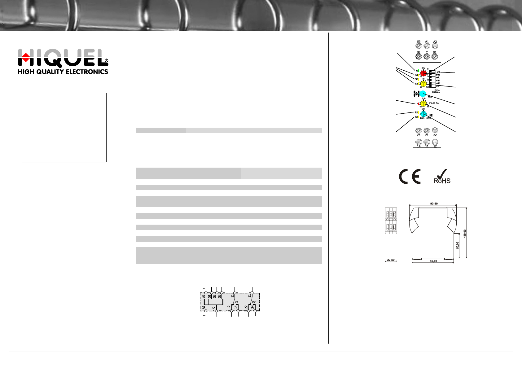
ANSCHLUSS / CONNECTION BLOCK DIAGRAM
Spannungsversorgung OK /
Supply voltage OK Funktionswahl /
Function setting
Zustand Sensor 1, 2, 3 /
Sensor status 1, 2, 3 Ausschaltverzögerungszeit /
Off-delay time
Einschaltverzögerungszeit /
On-delay time
Fehleranzeige / Error indicator
Reset-Taster / Reset-button
Ausgangsrelais 1 (Füllen/
Entleeren) aktiv / Output Alarmverzögerungszeit /
relay 1 (Fill/Empty) active Alarm delay time
Ausgangsrelais 2 (Alarm) aktiv / Sensorempfindlichkeit /
Output relay 2 (Alarm) active Sensor sensitivity
ZULASSUNG & KENNZEICHNUNG / TYPE APPROVAL INFORMATION
ABMESSUNGEN / DIMENSIONS (mm)
MONTAGE / MOUNTING
Die Montage ist mittels Schnapp-Befestigung
auf einer symmetrischen Hutschiene nach
DIN EN 50022 vorzunehmen. Die Geräte
sind für dicht an dicht Montage bei einer
Umgebungstemperatur von -20 bis + 60°C
geeignet.
Lever opens the spring clip on the base to
mount device on a symmetrical DIN rail
according to DIN EN 50022. The devices are
suitable for mounting side by side without an
air gap with an ambient temperature range
from -20 to + 60°C.
Copyright © 2008 by HIQUEL GmbH, Bairisch Kölldorf 266, 8344 Bad Gleichenberg, AUSTRIA. Alle Rechte vorbehalten, All rights reserved. 1

Kontrollrelais / Monitoring-relay –
in-
case – Füllstandsüberwachung / Liquid level monitoring – ICL
Detailbeschreibung (Deutsch)
Das Kontrollrelais ICL aus der in-case Serie ermöglicht die Überwachung und/oder
Regelung von bis zu 3 Füllständen. Die Ein- und Ausschaltverzögerungszeiten des
Füll- und Entleerrelais sowie des Alarmrelais können über Potentiometer an der
Frontseite eingestellt werden. Die Ausgangsrelais sind als 1-fache Wechsler
ausgeführt.
SPANNUNGSVERSORGUNG
(A1) L / L1
(A2) N / L2
Hinweis:
Der zulässige Spannungsbereich ist von der Nennspannung des
jeweiligen Gerätes abhängig!
MESSUNG
(S1) Niveaufühler für „Füllen/Leeren“
(S2) Niveaufühler für „Füllen/Leeren“ (nur bei Betriebsart „2 Sensoren“)
(S3) Niveaufühler für „Alarm“
ANZEIGEELEMENTE
U grün EIN Die Versorgungsspannung ist vorhanden.
S1 gelb BLINKEND Sensor 1 ist bedeckt.
S2 gelb BLINKEND Sensor 2 ist bedeckt.
S3 gelb BLINKEND Sensor 3 ist bedeckt.
F rot EIN Es liegt entweder ein Einstellungsfehler oder ein interner
R1 gelb EIN Das Ausgangsrelais 1 (Füllen/Entleeren) ist aktiv.
R2 gelb EIN Das Ausgangsrelais 2 (Alarm) ist aktiv.
BEDIENELEMENTE
Alle Bedienelemente der in-case Serie sind farbcodiert. Zeiteinstellungen sind
generell in gelb, Reaktionszeiten in rot, Einstellwerte in blau und Hysteresen in
grau gehalten.
tr rot Potentiometer zur Einstellung der Ausschaltverzögerungszeit des
(Einstellbereich: 0-5 Sekunden).
te gelb Potentiometer zur Einstellung der Einschaltverzögerungszeit des
(Einstellbereich: 0-10 Sekunden).
MR blau Wurde ein Fehlerzustand erkannt, kann durch Drücken der MR-
Hinweis:
NICHT Nullspannungssicher (Auslieferungszustand): Bei Ausfall
Nullspannungssicher: Bei Ausfall der Versorgungsspannung bleibt
Auf Grund des Messverfahrens, sind Sicherheits- und funktionstechnisch folgende Einschränkungen zu beachten:
• Die Leitfähigkeit muss innerhalb des zulässigen Bereichs liegen!
• Die Flüssigkeit darf sich durch die Messung nicht entzünden!
• Die Sensorleitungen müssen geschirmt ausgeführt und getrennt
von den Netzleitungen verlegt werden!
Programmfehler vor oder das Gerät führt gerade einen
Funktionswechsel durch.
Ausgangsrelais 1 „Füllen/Entleeren“.
Ausgangsrelais 1 „Füllen/Entleeren“.
Taste der (gespeicherte) Fehlerzustand zurückgesetzt werden.
Das ICL unterstützt zwei unterschiedliche Varianten des
manuellen Zurücksetzens:
der Versorgungsspannung wird ein gegebenenfalls vorhandener
Fehlerzustand zurückgesetzt.
ein gegebenenfalls vorhandener Fehlerzustand gespeichert. Ein
Fehlerzustand kann nur durch Anlegen der Versorgungsspannung
und anschließender Betätigung des MR-Tasters zurückgesetzt
werden. Ein Betätigen des MR-Tasters ohne Versorgungsspannung bleibt wirkungslos!
(Umschaltung NICHT Nullspannungssicher / Nullspannungssicher
tr+te AL gelb Potentiometer zur Einstellung der Ein- und Ausschaltverzöge-
(Einstellbereich: 0-5 Sekunden)
SE blau Potentiometer zur Einstellung der Sensorempfindlichkeit. Bei
Hinweis:
DIP-Schalter Funktionswahl
A/M Automat. Reset (A):
FI/EM Füllen (FI):
/AL Minimum Alarm ():
n/vR1 R1 Normal (n):
n/vR2 R2 Normal (n):
S1/S12 1 Sensor (S1):
Hinweis: Die Funktionen können beliebig kombiniert werden.
siehe Sonderbetriebsarten)
rungszeit des Ausgangsrelais 2 „Alarm“.
Unterschreitung des eingestellten Widerstandswertes wird der entsprechende Sensor als bedeckt erkannt.
Der Widerstandsverlauf des Potentiometers ist logarithmisch. Die Schalthysterese ändert sich linear über den Einstellbereich von +/-20% bei 100Ω bis +/-5% bei 100kΩ.
Das Zurücksetzen des
Fehlerzustandes erfolgt
automatisch.
nungssicherheit ist von der gewählten Sonderbetriebsart abhängig!
Grundfunktion des
Relais: „Behältnis
füllen“.
Der Alarmausgang wird
bei Erkennung eines
leeren Behältnisses
(„Trockenlauf“) aktiviert.
Das Ausgangsrelais 1
„Füllen / Leeren“ wird
der Normalfunktion
entsprechend angesteuert.
Das Ausgangsrelais 2
„Alarm“ wird der Normalfunktion entsprechend angesteuert.
„Füllen/Leeren“ mit 1
Sensor.
Manueller Reset (M):
Das Zurücksetzen des
Fehlerzustandes erfolgt
durch Drücken der MRTaste.
Hinweis:
Die Nullspan-
Leeren (EM):
Grundfunktion des
Relais: „Behältnis
leeren“.
Maximum Alarm
(AL):
Der Alarmausgang wird
bei Erkennung eines
vollen Behältnisses
(„Überlauf“) aktiviert.
R1 Invertiert (vR1):
Die Funktion des Ausgangsrelais 1 „Füllen /
Leeren“ ist invertiert.
R2 Invertiert (vR2):
Die Funktion des Ausgangsrelais 2 „Alarm“ ist
invertiert.
2 Sensoren (S12):
„Füllen/Leeren“ mit 2
Sensoren (Hysterese).
Anwendungsbeispiele:
Füllen mit 1 Sensor und Maximum Alarm
FÜLLEN: Sinkt das Niveau im Behältnis unter das Niveau von Sensor 1 (S1),
beginnt die Einschaltverzögerungszeit (te) zu laufen. Nach Ablauf der Einschaltverzögerungszeit (te) wird das Relais „Füllen/Entleeren“ (R1) aktiviert. Steigt das
Niveau im Behältnis über das Niveau von Sensor 1 (S1), beginnt die Ausschaltverzögerungszeit (tr) zu laufen. Nach Ablauf der Ausschaltverzögerungszeit (tr) wird
das Relais „Füllen/Entleeren“ (R1) deaktiviert.
ALARM: Steigt das Niveau im Behältnis über das Niveau von Sensor 3 (S3),
beginnt die Ein- und Ausschaltverzögerungszeit (tr+te AL) zu laufen. Nach Ablauf
dieser Zeit wird das Relais „Alarm“ (R2) aktiviert. Sinkt das Niveau im Behältnis
wieder unter das Niveau von Sensor 3 (S3), beginnt die Ein- und Ausschaltverzögerungszeit (tr+te AL) erneut zu laufen. Nach Ablauf dieser Zeit wird das Relais
„Alarm“ (R1) wieder deaktiviert.
Füllen mit 2 Sensoren und Maximum Alarm
FÜLLEN: Sinkt das Niveau im Behältnis unter das Niveau von Sensor 1 (S1) UND
Sensor 2 (S2), beginnt die Einschaltverzögerungszeit (te) zu laufen. Nach Ablauf
der Einschaltverzögerungszeit (te) wird das Relais „Füllen/Entleeren“ (R1) aktiviert.
Steigt das Niveau im Behältnis über das Niveau von Sensor 1 (S1) UND Sensor 2
(S2), beginnt die Ausschaltverzögerungszeit (tr) zu laufen. Nach Ablauf der Ausschaltverzögerungszeit (tr) wird das Relais „Füllen/Entleeren“ (R1) deaktiviert.
ALARM: Steigt das Niveau im Behältnis über das Niveau von Sensor 3 (S3),
beginnt die Ein- und Ausschaltverzögerungszeit (tr+te AL) zu laufen. Nach Ablauf
dieser Zeit wird das Relais „Alarm“ (R2) aktiviert. Sinkt das Niveau im Behältnis
wieder unter das Niveau von Sensor 3 (S3), beginnt die Ein- und Ausschaltverzögerungszeit (tr+te AL) erneut zu laufen. Nach Ablauf dieser Zeit wird das Relais
„Alarm“ (R1) wieder deaktiviert.
Copyright © 2008 by HIQUEL GmbH, Bairisch Kölldorf 266, 8344 Bad Gleichenberg, AUSTRIA. Alle Rechte vorbehalten, All rights reserved. 2

Kontrollrelais / Monitoring-relay –
in-
case – Füllstandsüberwachung / Liquid level monitoring – ICL
Entleeren mit 1 Sensor und Minimum Alarm
ENTLEEREN: Steigt das Niveau im Behältnis über das Niveau von Sensor 1 (S1),
beginnt die Einschaltverzögerungszeit (te) zu laufen. Nach Ablauf der Einschaltverzögerungszeit (te) wird das Relais „Füllen/Entleeren“ (R1) aktiviert. Sinkt das
Niveau im Behältnis unter das Niveau von Sensor 1 (S1), beginnt die Ausschaltverzögerungszeit (tr) zu laufen. Nach Ablauf der Ausschaltverzögerungszeit (tr)
wird das Relais „Füllen/Entleeren“ (R1) deaktiviert.
ALARM: Sinkt das Niveau im Behältnis unter das Niveau von Sensor 3 (S3),
beginnt die Ein- und Ausschaltverzögerungszeit (tr+te AL) zu laufen. Nach Ablauf
dieser Zeit wird das Relais „Alarm“ (R2) aktiviert. Steigt das Niveau im Behältnis
wieder über das Niveau von Sensor 3 (S3), beginnt die Ein- und Ausschaltverzögerungszeit (tr+te AL) erneut zu laufen. Nach Ablauf dieser Zeit wird das Relais
„Alarm“ (R1) wieder deaktiviert.
Entleeren mit 2 Sensoren und Minimum Alarm
ENTLEEREN: Steigt das Niveau im Behältnis über das Niveau von Sensor 1 (S1)
UND Sensor 2 (S2), beginnt die Einschaltverzögerungszeit (te) zu laufen. Nach
Ablauf der Einschaltverzögerungszeit (te) wird das Relais „Füllen/Entleeren“ (R1)
aktiviert. Sinkt das Niveau im Behältnis unter das Niveau von Sensor 1 (S1) UND
Sensor 2 (S2), beginnt die Ausschaltverzögerungszeit (tr) zu laufen. Nach Ablauf
der Ausschaltverzögerungszeit (tr) wird das Relais „Füllen/Entleeren“ (R1) deaktiviert.
ALARM: Sinkt das Niveau im Behältnis unter das Niveau von Sensor 3 (S3),
beginnt die Ein- und Ausschaltverzögerungszeit (tr+te AL) zu laufen. Nach Ablauf
dieser Zeit wird das Relais „Alarm“ (R2) aktiviert. Steigt das Niveau im Behältnis
wieder über das Niveau von Sensor 3 (S3), beginnt die Ein- und Ausschaltverzögerungszeit (tr+te AL) erneut zu laufen. Nach Ablauf dieser Zeit wird das Relais
„Alarm“ (R1) wieder deaktiviert.
Legende:
U Versorgungsspannung
Y Füllstand
S1 Position Sensor 1 („Füllen/Entleeren“)
S2 Position Sensor 2 („Füllen/Entleeren“)
S3 Position Sensor 3 („Alarm“)
te Einschaltverzögerungszeit Relais 1 „Füllen/Entleeren“
tr Ausschaltverzögerungszeit Relais 1 „Füllen/Entleeren“
tr+te AL Ein- und Ausschaltverzögerungszeit Relais 2 „Alarm“
t Zeit
Hinweis:
Einstellungen der Bedienelemente können generell während des
Betriebes durchgeführt werden. Wird eine Funktions- oder Schaltpunktänderung durchgeführt, so ist zur Kontrolle kurzzeitig die rote F-LED aktiv. Die
geänderten Einstellungen werden sofort übernommen und ausgeführt. Die
Ausgangsstufe kann, je nach Veränderung der Einstellung, unter Umständen
kurzzeitig ein- oder ausschalten.
AUSGANGSRELAIS 1 „Füllen/Leeren“ und 2 „Alarm“:
Aktiv Der Zustand ergibt sich funktionsbedingt.
Inaktiv Der Zustand ergibt sich funktionsbedingt oder es liegt ein Gerätefehler vor
(siehe Anzeigeelement F).
Hinweis:
Di e Ausgangsrelais sind galvanisch von der Versorgungsspannung
getrennt!
SONDERBETRIEBSARTEN
Folgende Sonderbetriebsarten stehen beim ICL zur Verfügung:
Nr 2 NICHT Nullspannungssicher
Nr 4 Nullspannungssicher
Das ICL ist bei Auslieferung auf „NICHT Nullspannungssicher“ eingestellt. Die
Umschaltung zwischen den einzelnen Sonderbetriebsarten kann folgendermaßen
durchgeführt werden:
1. DIP-Schalterstellung notieren
2. Versorgungsspannung abschalten
3. DIP-Schalter in folgende Stellung bringen:
4. MR-Taster drücken und gedrückt halten!
5. Versorgungsspannung einschalten
6. Sobald das Anzeigeelement F blinkt, kann die MR-Taste losgelassen werden
7. Mit jedem Druck auf die MR-Taste wird die Sonderbetriebsart umgeschaltet.
Die momentan aktive Sonderbetriebsart wird durch ein Blinksignal am Anzeigeelement F angezeigt. Das Blinksignal setzt sich folgendermaßen zusammen: Nummer der Sonderbetriebsart = Anzahl der Blinksignale kurz hintereinander, gefolgt von einer Pause. Dieses Signal wird permanent wiederholt.
Die zuletzt gewählte Sonderbetriebsart wird automatisch gespeichert.
8. Versorgungsspannung abschalten
9. ursprüngliche DIP-Schalterstellung wieder herstellen
10. Gerät kann wieder in Betrieb genommen werden
Detailed description (English)
The ICL monitors and/or controls up to 3 liquid levels. The on- and off-delay times
for the “Fill/Empty” and “Alarm” relays can be easily adjusted using the potentiometers on the front plate. The alarm output relays are SPCO.
SUPPLY-VOLTAGE
(A1) L / L1
(A2) N / L2
Note:
The supply-voltage range depends on the nominal voltage of the par-
ticular device!
MEASUREMENT
(S1) Liquid level sensor 1 „Fill/Empty“
(S2) Liquid level sensor 2 „Fill/Empty“ (only in 2 sensor mode)
(S3) Liquid level sensor „Alarm“
LED STATUS INDICATION
U green ON Supply voltage is OK
S1 yellow FLASH Sensor 1 is covered
S2 yellow FLASH Sensor 2 is covered
S3 yellow FLASH Sensor 3 is covered
F red ON Setting fault, internal program fault or changing the
R1 yellow ON Output relay 1 “Fill/Empty” is active
R2 yellow ON Output relay 2 “Alarm” is active
CONTROLS
The controls of the in-case series are color coded for simplicity. Blue potentiometers or rotary switches are used for set values, time settings are yellow, the time
range of a reaction timer is red, and percentage hysteresis is always grey.
tr red Potentiometer to adjust the off-delay time for output relay 1
te yellow Potentiometer to adjust the on-delay time for output relay 1
MR blue Pressing the MR-button resets an (stored) alarm.
Note:
Volatile manual reset (factory setting): If the ICL is in alarm
Non-volatile (Latched) manual reset: With this reset function, if
(for switching between volatile and non-volatile manual reset see
tr+te AL yellow Potentiometer to adjust the on- and off-delay time for output
Due to the used measuring method consider the following safety
and functional restrictions:
• The conductivity of the liquid has to be within the allowed range!
• The liquid must be non-flammable!
• The sensor cables must be shielded and installed separated from
the supply lines!
function mode
“Fill/Empty” (setting range: 0-5 seconds).
“Fill/Empty” (setting range: 0-10 seconds).
The ICL features 2 different manual reset functions:
mode, the alarm will be reset when the supply voltage is removed. The alarm can also be reset by pressing the MR-button
(without removing the power supply).
the ICL is in alarm mode when the supply voltage is removed,
the alarm condition will be electronically latched. Therefore when
the supply voltage is re-established the alarm condition will be
restored! The only way to reset the alarm is to press the MRbutton.
special operating modes)
relay 2 “Alarm” (setting range: 0-5 seconds)´
Copyright © 2008 by HIQUEL GmbH, Bairisch Kölldorf 266, 8344 Bad Gleichenberg, AUSTRIA. Alle Rechte vorbehalten, All rights reserved. 3

Kontrollrelais / Monitoring-relay –
in-
case – Füllstandsüberwachung / Liquid level monitoring – ICL
SE blue Potentiometer to adjust the sensor-sensitivity. If the resistance of
Note:
DIP-switches for basic functions
A/M Automatic Reset (A):
FI/EM Fill (FI):
/AL M inimum alarm ():
n/vR1 R1 normal (n):
n/vR2 R2 normal (n):
S1/S12 1 sensor (S1):
Note: These functions can be used in any combination.
a sensor falls below the adjusted resistance value the sensor will
be detected as “covered”.
The characteristic of the potentiometer is logarithmic. The
switching hysteresis changes linear over the whole range from
+/-20% at 100Ω to +/-5% at 100kΩ.
Automatic reset of an
alarm.
see special operating modes!
The basic function of
the relay is „Fill tank“.
On detecting an empty
tank (“dry running”) the
alarm output relay will
be activated.
The output relay 1
„Fill/Empty“ works
corresponding to the
normal function.
The output relay 2
„Alarm“ works corresponding to the normal
function.
„Fill/Empy“ with 1
sensor.
Manual reset (M):
An alarm can only be
reset by pressing the
MR-button.
Note:
For volatile / non-
volatile manual reset
Empty (EM):
The basic function of
the relay is „Empty
tank“.
Maximum alarm (AL):
On detecting a full tank
(“overrun”) the alarm
output relay will be
activated.
R1 inverted (vR1):
The output relay 1
function “Fill/Empty” is
inverted.
R2 inverted (vR2):
The output relay 2
function „Alarm“ is
inverted.
2 sensors (S12):
„Fill/Empty“ with 2
sensors (hysteresis).
Examples:
Fill with 1 sensor and maximum alarm
FILL: If the liquid level falls below sensor 1 (S1), the on-delay time (te) starts. After
expiration of the on-delay time (te) the output relay “Fill/Empty” (R1) pulls in. If the
liquid level exceeds the level of sensor 1 (S1), the off-delay time (tr) starts. After
expiration of the off-delay time (tr) the output relay “Fill/Empty” (R1) drops out.
ALARM: If the liquid level exceeds the level of sensor 3 (S3), the delay time (tr+te
AL) starts. After expiration of the delay time the output relay “Alarm” (R3) pulls in. If
the liquid level falls below the level of sensor 3 (S3), the delay time (tr+te AL) starts
again. After expiration of the delay time the output relay “Alarm” (R3) drops out.
Fill with 2 sensors and maximum alarm
FILL: If the liquid level falls below sensor 1 (S1) AND sensor 2 (S2), the on-delay
time (te) starts. After expiration of the on-delay time (te) the output relay
“Fill/Empty” (R1) pulls in. If the liquid level exceeds the level of sensor 1 (S1) AND
sensor 2 (S2), the off-delay time (tr) starts. After expiration of the off-delay time (tr)
the output relay “Fill/Empty” (R1) drops out.
ALARM: If the liquid level exceeds the level of sensor 3 (S3), the delay time (tr+te
AL) starts. After expiration of the delay time the output relay “Alarm” (R3) pulls in.
If the liquid level falls below the level of sensor 3 (S3), the delay time (tr+te AL)
starts again. After expiration of the delay time the output relay “Alarm” (R3) drops
out.
Empty with 1 sensor and minimum alarm
EMPTY: If the liquid level exceeds sensor 1 (S1), the on-delay time (te) starts.
After expiration of the on-delay time (te) the output relay “Fill/Empty” (R1) pulls in. If
the liquid level falls below the level of sensor 1 (S1), the off-delay time (tr) starts.
After expiration of the off-delay time (tr) the output relay “Fill/Empty” (R1) drops out.
ALARM: If the liquid level falls below the level of sensor 3 (S3), the delay time
(tr+te AL) starts. After expiration of the delay time the output relay “Alarm” (R3)
pulls in. If the liquid level exceeds the level of sensor 3 (S3), the delay time (tr+te
AL) starts again. After expiration of the delay time the output relay “Alarm” (R3)
drops out.
Empty with 2 sensors and minimum alarm
EMPTY: If the liquid level exceeds sensor 1 (S1) AND sensor 2 (S2), the on-delay
time (te) starts. After expiration of the on-delay time (te) the output relay
“Fill/Empty” (R1) pulls in. If the liquid level falls below the level of sensor 1 (S1)
AND sensor 2 (S2), the off-delay time (tr) starts. After expiration of the off-delay
time (tr) the output relay “Fill/Empty” (R1) drops out.
ALARM: If the liquid level falls below the level of sensor 3 (S3), the delay time
(tr+te AL) starts. After expiration of the delay time the output relay “Alarm” (R3)
pulls in. If the liquid level exceeds the level of sensor 3 (S3), the delay time (tr+te
AL) starts again. After expiration of the delay time the output relay “Alarm” (R3)
drops out.
Copyright © 2008 by HIQUEL GmbH, Bairisch Kölldorf 266, 8344 Bad Gleichenberg, AUSTRIA. Alle Rechte vorbehalten, All rights reserved. 4

Kontrollrelais / Monitoring-relay –
Legend:
U Supply voltage
Y Liquid level
S1 Position sensor 1 („Fill/Empty“)
S2 Position sensor 2 („Fill/Empty“)
S3 Position sensor 3 („Alarm“)
te On-delay time relay 1 „Fill/Empty“
tr Off-delay time relay 1 „Fill/Empty“
tr+te AL On- and off-delay time relay 2 „Alarm“
t Time
Note:
It is not necessary to remove the supply voltage before making an y
changes in the setting of the controls. If either threshold or function is
changed the red LED-indicator F is active for a short time for checking purposes. The new settings are immediately active. Depending on the change of
the settings, the output relay might be switched off temporary.
OUTPUT RELAY 1 “Fill/Empty” and 2 “Alarm”
Active Condition depends on the function.
Inactive Condition depends on the function or the device has an internal fault
Note:
terminals!
SPECIAL OPERATING MODES
The following special operating modes are available for the ICL:
#2 Volatile
#4 Non-volatile
The factory setting is „#2 - Volatile“. To switch between the special operating
modes consider the following steps:
1. Write down the actual DIP-switch settings
2. Turn off the power supply
3. Change the DIP-switch positions as shown below:
4. Press the MR-button and keep pressed!
5. Turn on the power supply
6. As soon as the LED-indicator F flashes, the MR-button can be released
7. Every stroke on the MR-button changes the special operating mode. The
8. Turn off the power supply
9. Restore the original DIP-switch settings
10. The device can be put in operation again
(see LED-indicator F).
The output relays are galvanically isolated from the power supply
actual mode is indicated with a special flashlight signal on the LED-indicator
F. The flash signal is composed as follows: Number of operating mode =
number of flashlight signals followed by a short pause. This signal is repeated constantly. The last-selected special function mode is automatically
stored.
in-
case – Füllstandsüberwachung / Liquid level monitoring – ICL
Copyright © 2008 by HIQUEL GmbH, Bairisch Kölldorf 266, 8344 Bad Gleichenberg, AUSTRIA. Alle Rechte vorbehalten, All rights reserved. 5
 Loading...