

Page 1
SERVICE MANUAL
WARNING
This equipment is designed and built with safety in mind. However, your overall
safety can be increased by your full understand followed by the content in this
manual.
Read this manual and familiarize yourself with its contents for your safety.
This equipment should only be operated and maintained by trained and qualified
personnel.
This equipment is designed for arc welding and generating power source of
electric tools, home appliances and lights.
Do not install, operate or service this equipment without reading this manual and
unless you clearly understand this manual.
Generating application for this equipment is 60Hz ONLY.
Specifications subject to change without notice.
Page 2
File №DGW-360_HW400A
This service manual is edited for authorized person to perform repair,
maintenance, and trouble-shooting to HIPOWER Diesel Engine Generator
Welder, Model Designation HW400A.
It is inevitably necessary to maintain and adjust HIPOWER products
periodically in order to use fully and safely for long time. Therefore,
understand this service manual fully enough before use and proper
maintenance.
The information contained in this service manual describes equipment
available at the time of publication. While every attempt has been made to
give you the very latest information about your product, there may be some
differences between your equipment and the equipment described in this
manual. We reserve the right to make changes to equipments without prior
notice, and without obligation to make alterations to equipments previously
manufactured.
For service of the engine, refer to Workshop (Service) Manual provided by
the engine manufacturer described below.
MANUFACTURER
MODEL WORKSHOP MANUAL
Kubota D1005 05-E3B/05-E3BG Series
Page 3

Table of Contents
1. Attention Statements
····························································································
1
2. General Safety Ins tr uctions
···············································································
2
3. Specifi cat ions
···········································································································
4
4. General
························································································································
5
4-1 Appearance ····································································································· 5
4-2 Dimension ······································································································· 5
4-3 Welding Feature······························································································· 7
4.3.1 Duty Cycle ······························································································ 7
4.3.2 Low Noise and Low Fuel Consumption ····················································· 7
5. General Pa r ts Description
········································································· 8
5.1 Main Parts and Feature ···················································································· 8
5.2 Main Components ···························································································· 8
6. Ser vice Data
··············································································································
15
6.1 Periodical Check ······························································································ 15
6.2 Output Voltage (at no load)··············································································· 18
6.2.1 Output Voltage (at no load) ····································································· 18
6.3 Component Parts Resistance Value ·································································· 19
6.4 Display Mode by LED ······················································································· 20
6.5 Power Controller ······························································································ 21
(1) Generating Output Adjustment········································································· 21
(2) Welding Output Adjustment ············································································· 21
(3) CV Control Voltage Adjustment ······································································ 21
(4) Fuse··············································································································· 22
(5) Protection Feature ·························································································· 22
7. Tightening Torque
···································································································
23
7.1.1 Periodical Check for Engine··········································································· 24
8. Trouble Shooting
·····································································································
25
8.1 Engine won’t start ···························································································· 25
8.2 Weak arc ········································································································· 26
8.3 No Welding Arc ································································································ 27
8.4 No AC Output··································································································· 27
8.5 Check Rotor, Stator and Excitor Circuit ····························································· 28
8.6 Auto Idle won’t work ························································································· 29
8.7 Engine Speed won’t return to idle ····································································· 30
9. Wiring Diagram
····························································································· 31
9.1 Generator Wiring Diagram ················································································ 31
Page 4
1
1. Attention Statements
・Technicians only who own enough knowledge and experience should work for
maintenance and operational check after maintenance.
・Before maintenance, always read this service manual as well as owner’s manual and
familiarize contents thoroughly before starting the service and maintenance of the
equipment for understanding of the equipment, safety instructions and cautions.
・
Throughout this manual are special attention statements.
A statement preceded by the triangular attention symbol and the word “WARNING”
contains information that should be acted upon to prevent serious bodily injury.
A statement preceded by the triangular attention symbol and the word “CAUTION”
contains information that should be acted upon to prevent mechanical damage.
WARNING
CAUTION
Page 5
2
2. General Safety Instructions
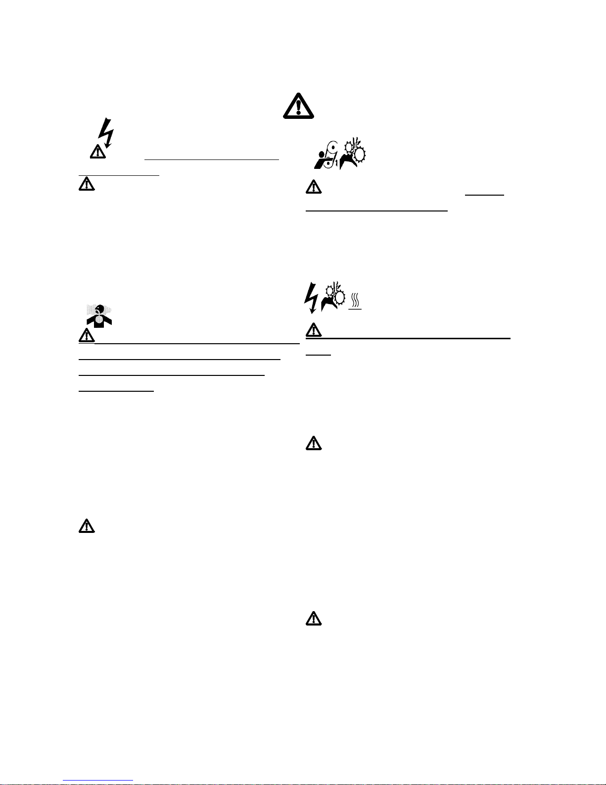
ELECTRIC SHOCK
NEVER touch the output terminals
during operation
NEVER touch the output terminal during
operation even though the breaker on the
load is being set at “OFF” position.
ALWAYS stop engine and make sure it
stopped before you will connect the loads to
the output terminals.
Suffocation by exhaust gas
NEVER run the engine indoors! Make
sure there is always good ventilation.
Fumes from engine exhaust cause
serious injury.
ALWAYS operate the equipment in the
ventilated area.
When the equipment is used in a tunnel, hall
or any other indoor, the equipment for
ventilation must be used to prevent serious
accident caused by suffocation.
NEVER direct the exhaust fume to
houses nearby while considering the wind
flow direction.
Exhaust gas contains many harmful
elements that would cause affect to human.
Be free from suffocation when the
equipment is used in poorly ventilated area
such as inside of the building.
Entangled Injuries under
By Moving Componen
t
NEVER reach and touch the moving
component during operation!
ALWAYS stop the engine during inspection
to prevent serious bodily injury by entangled
accident under moving component.
Electric shock/Injuries/Burns
Never inspect equipment during
use
.
Never serve and inspect when equipment is
being operated.
It may cause electric shock, injuries or
burns.
WARNING-Use good judgment
① NEVER run the engine when
transporting the equipment.
②
ALWAYS stop the equipment
immediately if it suddenly begins to
violate or abnormal noise. Inspect for
broken, missing or improperly installed
parts.
③
ALWAYS keep the equipment as clean
as practical. Keep it free of loose
vegetation, mud, etc.
DO NOT make unauthorized
modifications or alterations to this equipment
of any of its components. YAMABIKO must
authorize alterations and modifications in
writing. Unauthorized modifications or
alterations may alter the equipment
operation and could jeopardize personal
safety during operation.
WARNING
Page 6
3
Work Safely
Generators and welders operate at very high
speeds and can do serious damage or injury
if they are misused or abused. Never allow a
person without training or instruction to
operate and serve this equipment!
Attention to CAUTION LABEL!
Caution labels are placed on this equipment
and it would request special attention for
operation. Make sure to locate the labels
and understand the content of the caution.
・Check the caution labels is legible. Always
keep the labels clean or replace them when
worn or damaged
・Clean the labels by cloth, water or
detergent and never use organic solvent or
gasoline which may cause label peel off due
to adhesive solvent.
・Make sure to replace the labels when
damaged and illegible.
Before replacing the label(s), make sure to
place the new label(s) in the same position.
STOP the equipment immediately when
abnormal circumstances are noticed!
STSTOP the equipment immediately whenever
abnormal circumstances are noticed such
as unusual noise, smell, vibration and etc.
It may lead serious accident or fatal damage
of the equipment or properties.
Inflammables!
Keep the equipment far away from fire such
as cigarettes when refueling fuel, oil or
battery fluid.
NEVER operate or service the equipment
nearby fire as the equipment may catch
fire.
No Modification!
NEVER modify the equipment without
manufacturer’s advanced approval. .
It may lead serious safety issue and damage
the equipment.
Inspect the equipment before engine
start for operation and periodical inspection
without fail!
Make sure to serve initial check before start
engine and periodical inspection for safety
and longer life of the equipment.
CAUTION
Page 7
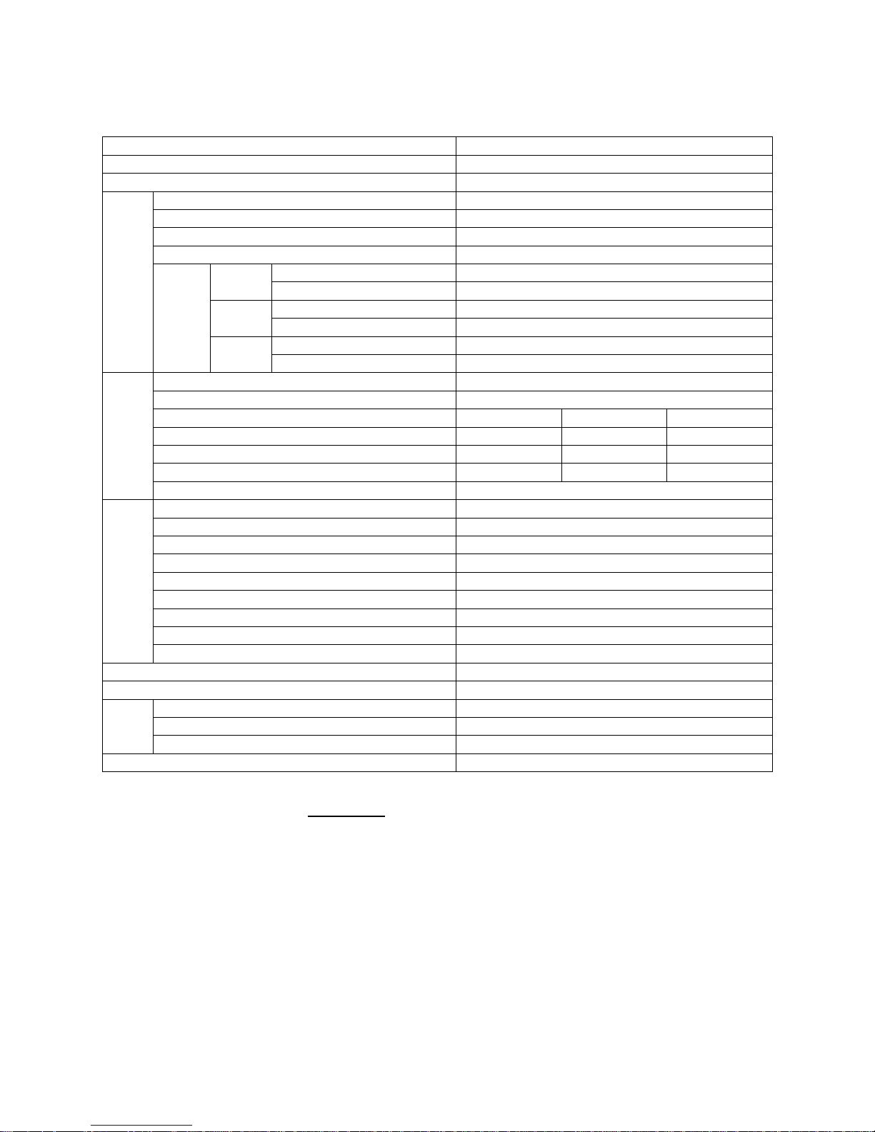
3. Specifications
Model Name HW400A
Model Code DGW400DM - C
Generating Method Rotating Field
Rated Current (A) 390 @ 60% Duty Cycle, 302 @ 100% Duty Cycle
Rated Voltage (V) 35.6
Rated Speed (rpm ) 3600
No Load Voltage (A) MAX 85
Current Adj. Range (A) 110 - 400 Single
Welding Rod Diameter (in.) 3/32 - 5/16
Current Adj. Range (A) 55 - 210 Dual
Welding Rod Diameter (in.) 5/64 - 5/32
Current Adj. Range (A) 40 - 220
Welding Generator
Output Change
(CC power)
Eco
Welding Rod Diameter (in.) 5/64 - 3/16
Rated Frequency (Hz) 60
Rated Speed (rpm ) 3600
Phase 1-Phase 1-Phase 3-Phase
Rated Voltage (V) 120 240 480
Power Factor 1.0 1.0 0.8
Rated Output (kVA) 2.2 4.3 15
AC Generator
Rating Continuous
Model Kubota D1005
Type Vertical, Water-Cooled 4-Cycle Diesel Engine
Displacement (cu.in./liters) 61/1.001
Rated Output (hp/rpm) 27.4/3600
Fuel ASTM No.2 Diesel Fuel or Equivalent
Lube Oil API Class CC or Higher
Lube Oil Volume (gal./liters) 1.35/5.1
Cooling Water Volume (gal./liters) 1.14/4.3
Engine
Starting Method 12V DC Starter Motor
Battery 12V-45AH(55B24L)
Fuel Tank Capacity (gal./liters) 9.8 /37
Length (in./mm) 59.8/1519
Width (in./mm) 27.6/700
Dimen
sion
Height (in./mm) 29.9/760
Dry Weight (lbs./kg) 972/441
* Specifications subject to change without notice.
** Generating application is for 60Hz ONLY.
4
Page 8
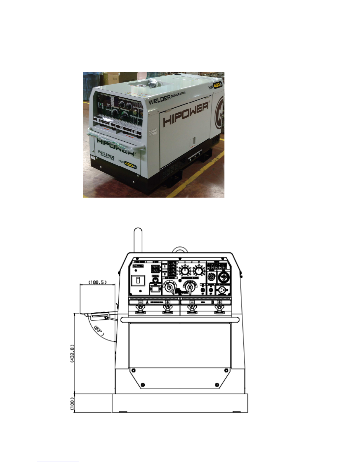
4. General
4.1 Appearance
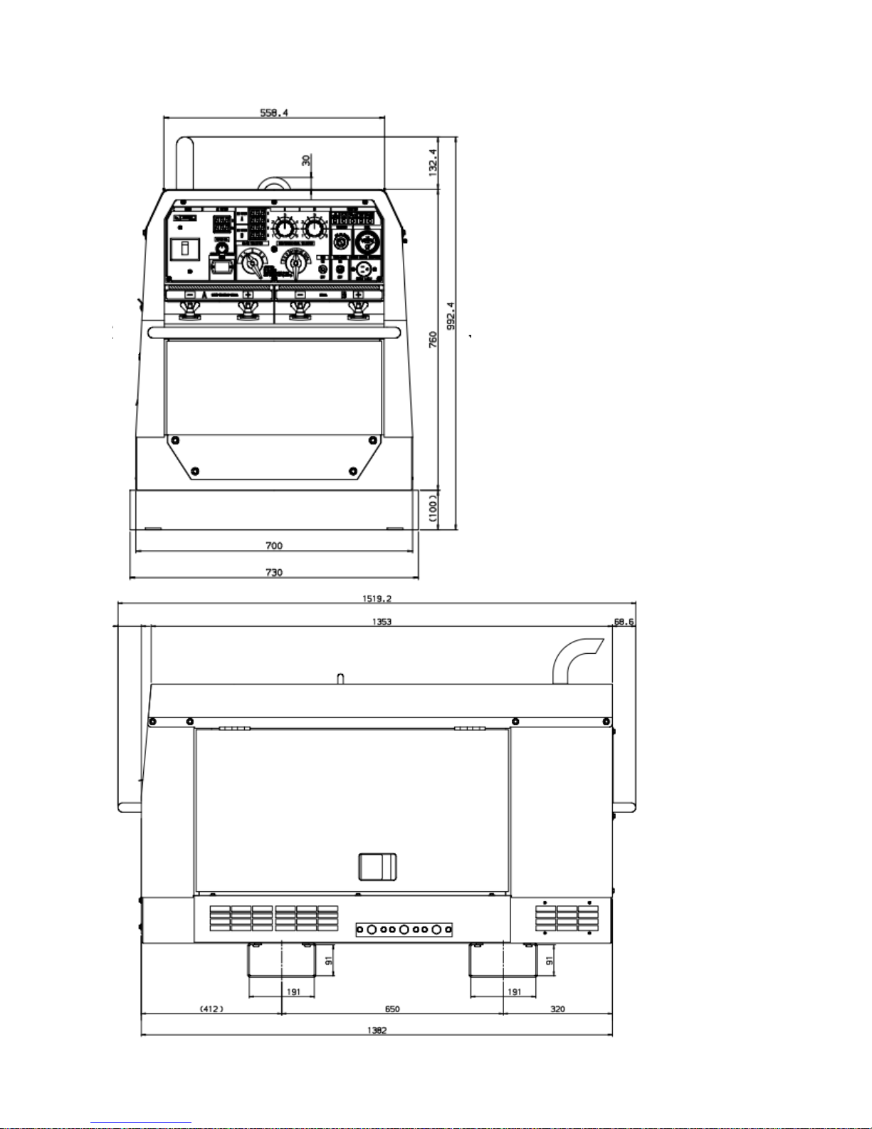
4.2 Dimension
Unit in the drawings below is shown by mm.
5
Page 9
6
Page 10
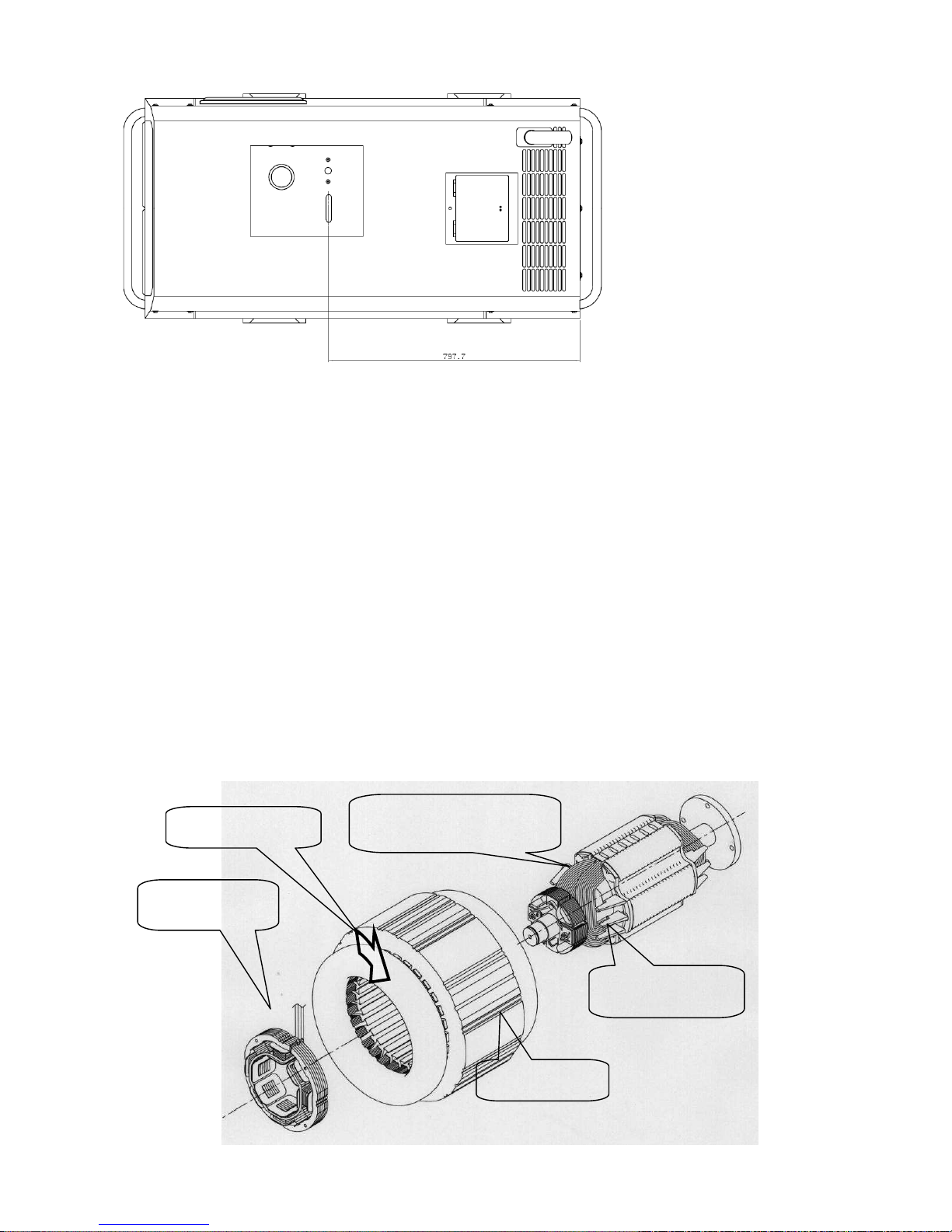
Rotor for Multi-Pole
Welder and Generator
Main Stator
Exciter Stator
(Magnetic field)
Exciter(Armature)
Rotor
Short pitch Coil
4.3 Welding Feature
4.3.1 Duty Cycle
・
High efficient alternator has achieved the rated duty cycle 60% for 390A and 100%
for 302A.
Multi-pole rotor has made the stator winding pitch short (i.e. coil length short) which
has brought the coil resistance decreasing. In addition to it, bigger diameter coil has
also brought coil resistance decreasing. These factors have made the alternator high
efficient.
・The high efficient alternator has decreased the engine load
The high efficiency alternator has decreased the load to engine, which will bring the
engine life longer. In addition to that, it has become less occasion of engine
overheat owing to wider engine power margin.
4.3.2 Low Noise and Low Fuel Consumption
・The engine speed is automatically controlled to comply with the load, which has made
low noise and fuel consumption. The fuel consumption is remarkably low. It is
approx. 29 hour successive operation at 220A welding with full fuel tank, for example.
7
Page 11
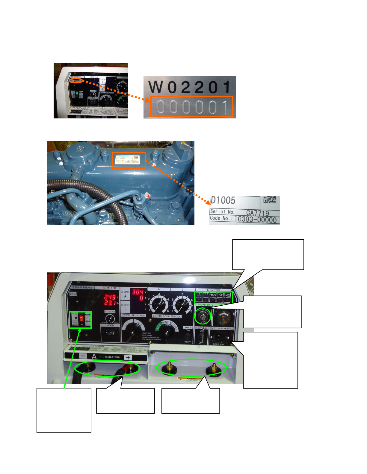
5. General Parts Description
5.1 Main Parts and Feature
(1) Unit Serial Number
(2) Engine Serial Number
5.2 Main Components
8
M
onitor Lamp
Feature: Light a monitor
lamp when equipment is
malfunctioned.
Starter Switch
Feature: Selector
switch to start, stop
and preheat engine
Welding Terminal B
Feature: Connect
welding terminal.
Remote Control
Receptacle
Feature: Receptacle
to Incorporates
with a remote
control box.
Remote control
box is optional.
Welding Terminal A
Feature: Connect
welding terminal.
Circuit Breaker
Feature: P
rotect
electrical circuit
from damage by
overload or short
circuit.
Page 12
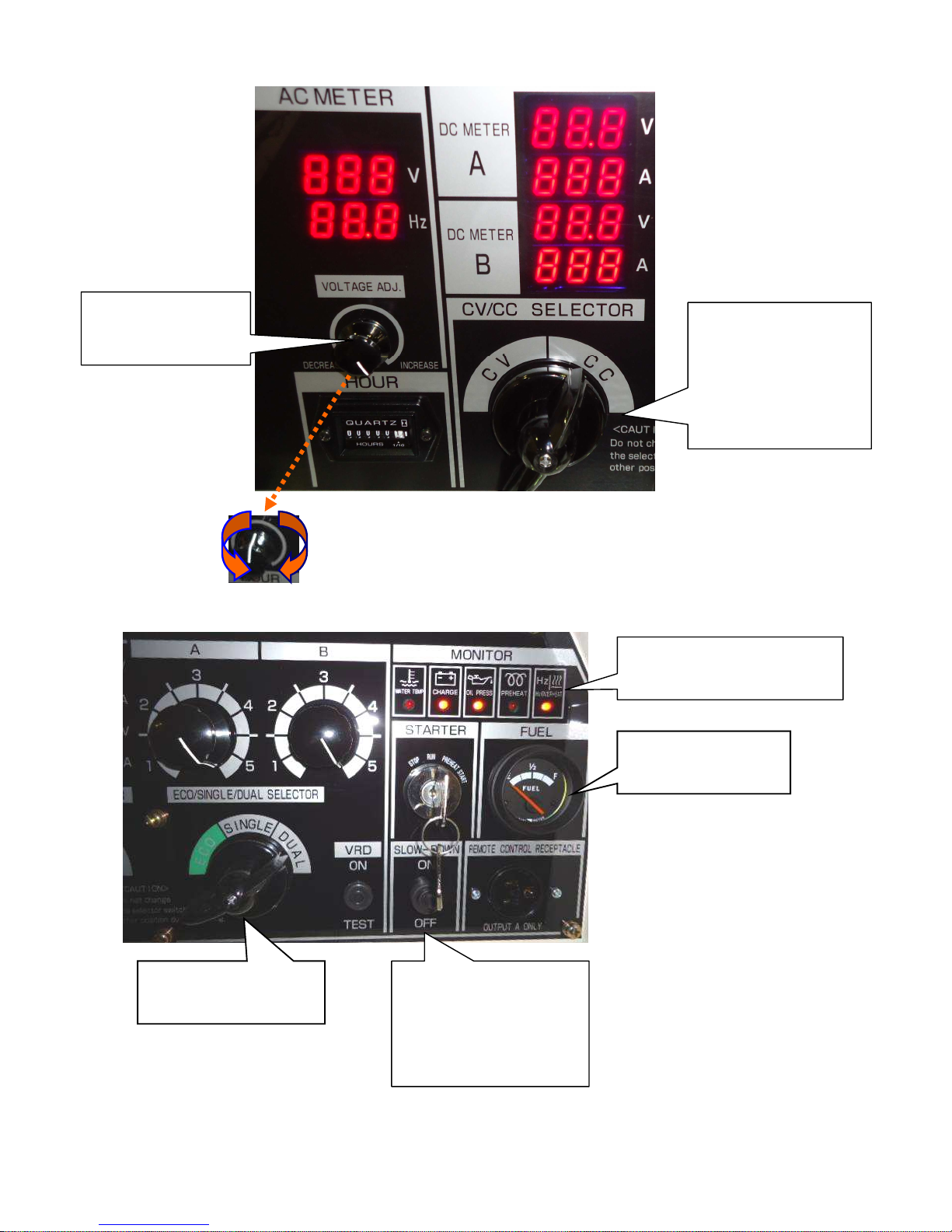
9
Decrease Increase
CC/CV Selector Switch
Feature:
Voltage is adjusted when
the switch is turned to CV.
Current is adjusted when
the switch is turned to CC.
Caution: Do not change
the selector switch when
welding.
AC Voltage Adjusting
Dial
Feature: A dial to adjust
AC output.
Fuel
Meter
Feature:
Display fuel
volume in the fuel tank.
Output Selector S
witch
Feature: Change output
by adjusting engine speed.
Slow-Down Switch
Feature: Set the engine
speed idle when welding
or electric supply is not
performed to reduce noise
and fuel consumption.
Monitor Lamp
Feature: Light a monitor lamp
when equipment is malfunctioned.
Page 13
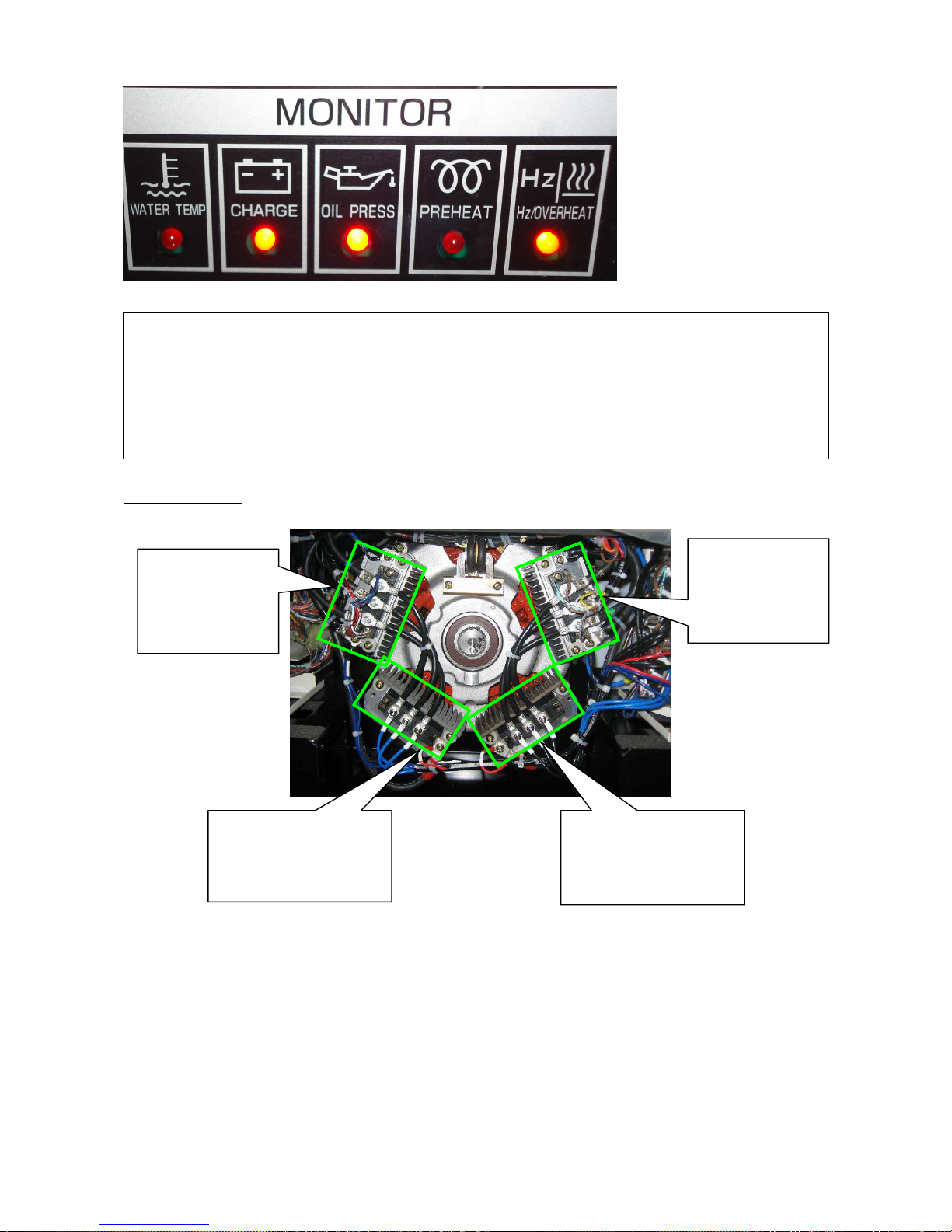
Front Door Inside
Thyristor
Feature: Control A
side welding current
combined with
rectifier and rectify
AC to DC.
Thyristor
Feature: Control B
side welding current
combined with
rectifier and rectify
AC to DC.
Rectifier
Feature: Rectify A side
welding current combined
with thyristor, rectified AC
to DC
Rectifier
Feature: Rectify B side
welding current combined
with thyristor and rectify AC
to DC.
10
This unit is equipped with monitoring functions and the cautioned lamp flashes to indicate defect.
Investigate and
correct cause(s) when any of the monitor lamps turns on.
WATER TEMP: when a coolant temperature rises higher than 230°i n Fahrenheit.
CHARGE: when a battery charge is insufficient.
OIL PRESS: when oil pressure is dropped below 7 psi.
PREHEAT:Pre-Heating Lamp is ON when a starter switch is turned to “PREHEAT” position.
OVERHEAT: when temperature of the coolant will reach to 105℃. Engine will automatically shut down.
Page 14
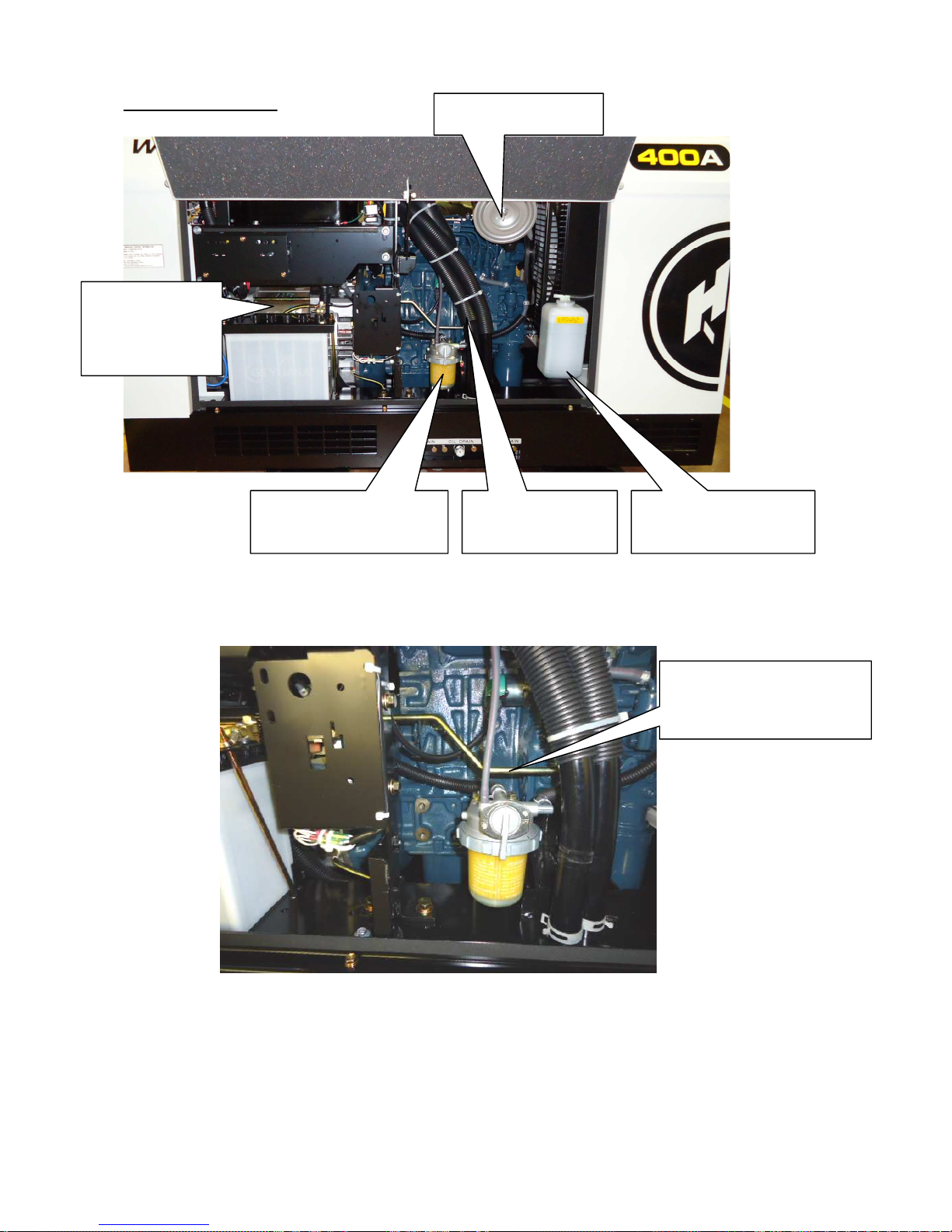
Right Side Door Inside
Speed Adj. Rod
Feature: Control speed
adjusting motor with a governor
lever.
Fuel Filter
Feature: Filter water or dust
in the fuel.
Sub Tank
Feature: Keep coolant
water level in the radiator.
Drain Hose
Feature: Drain water
from the top cover.
Generator
Feature: A device to
convert mechanical
energy to electrical
energy.
Air Cleaner
Feature: Clean intake air.
11
Page 15
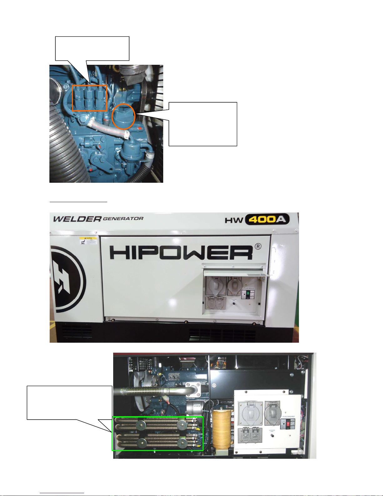
Left Side Door Inside
Engine
O
il Inlet
Feature: Inlet to inject
engine oil.
Use the oil of CD or
higher grade in American
Petroleum Insti
tute.
Injection Pump
Feature: Supply fuel to the
injection nozzle.
12
Resistor
Feature: Upgrade welding
feature, increasing voltage at no
load with rectifier.
Page 16
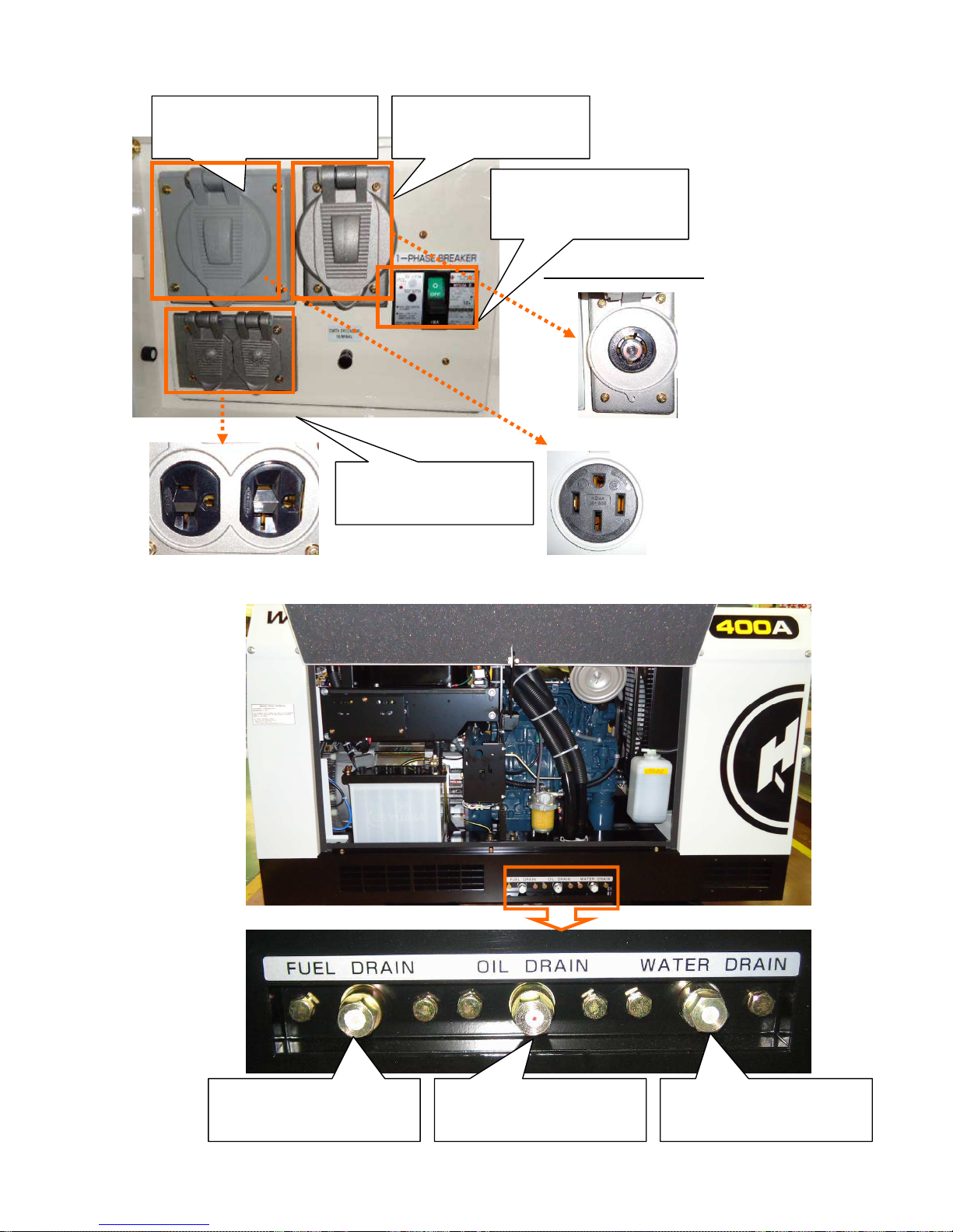
1
3
Circuit Breaker
Feature: Protect an electric
circuit from damage by
overload or short circuit.
3-Phase Receptacle (480V)
Feature: Supply AC output.
Max. output: 15kVA (12kW)
1-Phase Receptacle (120V)
Feature: Supply AC output.
Max. output: 2.2kVA (2.2kW)
1-Phase Receptacle (120/240V)
Feature: Supply AC output.
Max. output: 4.3kVA (4.3kW)
Receptacle Inside View
Fuel Drain Plug
Feature: Drain the old fuel from
the fuel tank.
Oil Drain Plug
Feature: Drain the old oil from
the oil tank.
Water Drain Plug
Feature: Drain water from the
top cover.
Page 17
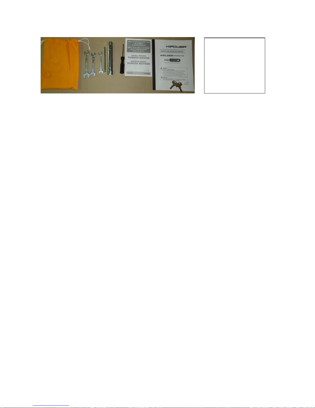
14
Sta
ndard Accessory
① Owners Manual
② Engine Manufacturer’s
Warranty Statement
③ Starter Key – 2 sets
④ Tool Set
・ Tool Bag
・ Screw Driver
・ Plug Wrench
・ Spanner – 3 sets
Page 18
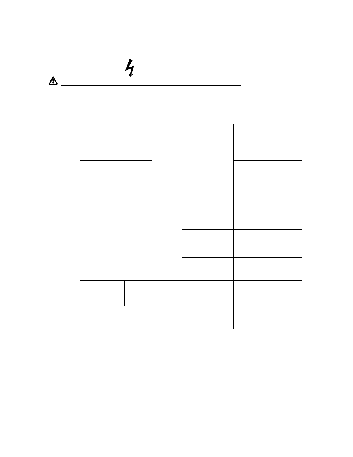
6. Service Data
6.1 Periodical Check
ELECTRIC SHOCK
Never touch the output terminals during operation.
Never touch the output terminal during operation even though the breaker on the load being set at
OFF.
Be sure to check and confirm the engine stop whenever touching terminals to connect loads.
Items Article Method Condition to verify Criterion
Shape, Dent, Blot
No dent, blot and
Deformation
Coating No looseness
Joint Meet the criteria
Oil, Coolant
Meet the required
Level
Check
before
operation
Wiring
Visual
Inspection
Lead wires to be securely
fastened against abrasion
and damage to bring by
vibration
Bracket -3 phase
Terminal
Over 10MΩ at DC500V
(Disconnect grounding)
Insulation
Check
Insulation Resistance
Optional
Tester
Bracket-Side A
Terminal (welding)
AC2400 (2 seconds)
Starter Switch -
Preheat
Preheat Lamp 5+/-1 sec. ON
Starter Switch – Run
Oil Pressure, Charging
Lamps, Fuel Lamp and
Voltage Lamp ON
Hour Meter & Speed Meter
Lamp OFF
Replace Display
Switch
Monitor Operation
Visual
Inspection
Engine Running
Hour Meter and Speed
Meter Lamp ON
Oil, Charging Lamp ON,
Hour Meter Revolving
Slow Slow-down ON 2100+/-20 min-1
No Load
60Hz
Optional
Tester
Slow-down OFF 3800+/-20 min-1
Operational
Check
During operation
Hearing &
Visual
Slow-down ON, OFF
No abnormal noise and
vibration
15
Page 19
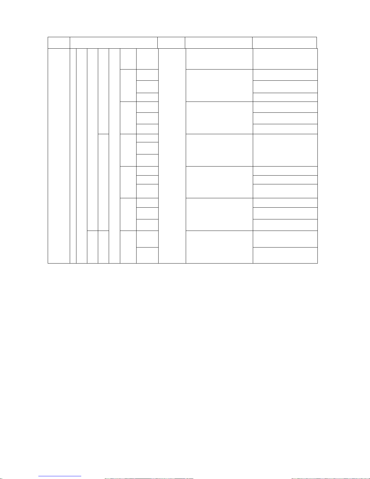
Items
Article Method Condition to verify Criterion
No
Load
V
Slow-down OFF
Voltage Regulator Max
82.0+/-3V
A 335+/-5A ※1
V 42.0+/-2V
Loaded
Min-1
Current Adj. Dial MAX
Slow-down ON
Rod φ6mm
Over 3150 min-1
A Over 400A
V Over 32V
Single
Loaded
Min-1
Current Adj. Dial MAX
Slow-down ON
Rod φ6mm
Over 3300 min-1
A
V
No Load
min-1
Current Adj. Dial MAX
Slow-down OFF
Rod φ6mm
82.0+/-3V
A
Over 160A ※1
V 42.0+/-2V
Loaded
min-1
Current Adj. Dial MAX
Slow-down ON
Rod φ6mm
Over 1750 min-1
A Over 220A
V Over 28.5V
CC
Eco
Loaded
min-1
Current Adj. Dial MAX
Over 1800 min-1
A 100+/-5A
Welding Output Check
60Hz
Output Terminal A
CV
Single
Regular Max
Loaded
V
Optional Tester
Current Adj. Dial MAX
43+/-2V
16
Page 20
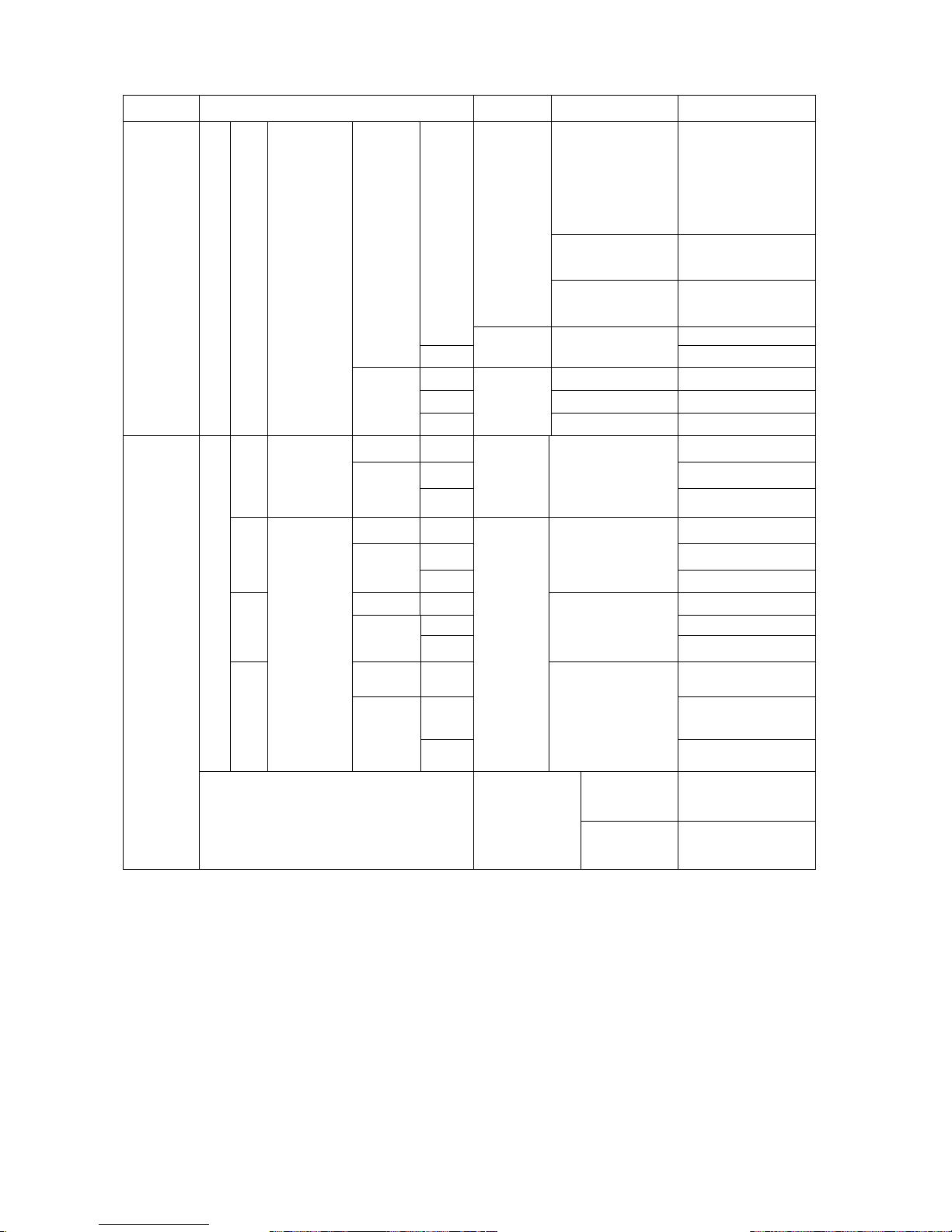
Items Article Method Condition to verify
Criterion
Slow-down OFF
Output Adj. Dial
Max.
556+/-25V
Slow-down OFF
Output Adj. Dial
Min
421+/-20V
Optional
Tester
Output Adj. Dial
Terminals: U-V,
V-W, W-U
480+/-3V
V
480+/-6V
No Load
Hz
Meter
attached
Ditto
63+/-1Hz
A Ditto 14.4+/-0.5A
V 482+/-6V
Generating Output Check
60 Hz
Single
3-Phase
480V
Loaded
min
-1
Optional
Tester
3740+/-50 min-1
No Load
V 240+/-1V
A 18.0+/-0.5A
Single
1-Phase
240V
Loaded
V
Optional
Tester
Output Adj. Dial
Terminals: T-R
248+/-6V
No Load
V
120+/-1V
A 18.0+/-0.5A
Single
Loaded
V
Output Adj. Dial
Terminals: R-N
120+/-3V
1-Phase
120V
No Load
V 68+/-3V
A 18.0+/-0.5A
Eco
Loaded
V
Output Adj. Dial
Terminals: N-T
120+/-3V
No Load
V 120+/-3V
A 18.0+/-0.5A
60Hz
Single
Loaded
V
Optional
Tester
Single Receptacle
120+/-3V
Loaded Run at regular speed
Generating Output Check
Slow-down Feature
Slow-down
ON
Load Cut
Return to Slow-down
in 8+/-2 second
1: Adjust the value by Power Controller VR2, finding it out of the required value range.
Spray screw lock bond (Recommendation - Three Bond No.1401C, Red) after adjusting.
Refer to “6.5 Power Controller”.
17
Page 21
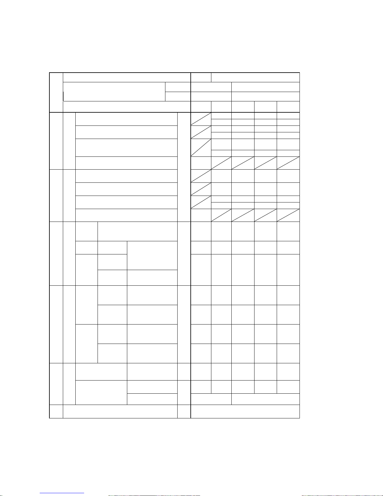
6.2 Output Voltage (at no load)
6.2.1 Output Voltage (at no load)
Welding Selector Switch Eco Single/Dual
Speed Slow Normal
Engine
RPM 2100±20min-1 3800±20min-1
No.
AC Output Voltage Adj. Dial Position
Full
Range
Full
Range
Min. Mid. Max.
45
77 82 84
Single
[45] [75] [82] [84]
44
74 80 82
Dual (A)
[44] [74] [80] [83]
6.3
[6.3]
6.0
[6.0]
8.5
[8.2]
9.6
[9.5]
Dual (B)
44 [43] 74 [74] 79 [79] 82 [83]
81
1
DC output (CC)
Eco
[81]
45
74 79 82
Single
[45] [74] [79] [82]
44
74 80 82
Dual (A)
[44] [74] [80] [81]
44
74 79 82
Dual (B)
[43] [74] [79] [83]
58
2
DC Output (CV)
Eco
DC
[58]
3-P
480V
U-V
V-W
W-U
268
[266]
325
[321]
417
[414]
480
[475]
552
[548]
1-P
240V
R-T
137
[144]
166
[173]
213
[223]
245
[255]
280
[290]
R-N
N-T
1P 3 Wire
Receptacle
3
AC Output
1-P
120V
R-N
1P 2 Wire
Receptacle
AC
67
[72]
83
[86]
105
[110]
122
[128]
140
[145]
AU-AV
AV-AW
AW-AU
(R)-(W)
(W)-(L)
(L)-(R)
35
[35]
35
[35]
56
[56]
60
[61]
62
[63]
Side A
AU-OA
AV-OA
AW-OA
(R)-(Gr)
(W)-(Gr)
(L)-(Gr)
20
[20]
20
[20]
34
[34]
35
[36]
36
[37]
BU-BV
BV-BW
BW-BU
(B)-(Y)
(Y)-(G)
(G)-(B)
35
[35]
35
[35]
55
[55]
60
[60]
61
[62]
4
Welding Coil
Side B
BU-OB
BV-OB
BW-OB
(B)-(Br)
(Y)-(Br)
(G)-(Br)
AC
20
[20]
20
[20]
33
[33]
35
[35]
35
[36]
Stator
Excitor
Wiring
「F-F」
AC
24
[25]
26
[27]
35
[37]
41
[43]
46
[48]
Input V Adj.Coil
(R)-(L)
9
[9]
22
[22]
1.2
[1]
3.8
[4]
8.4
[9]
5
Exciter Coil
Exciter
Stator
Compensate Coil
(Or)-(Br)
DC
2.6
[3]
2.6
[3]
6 Charging Dynamo Voltage DC
13.5
[14]
18
Page 22
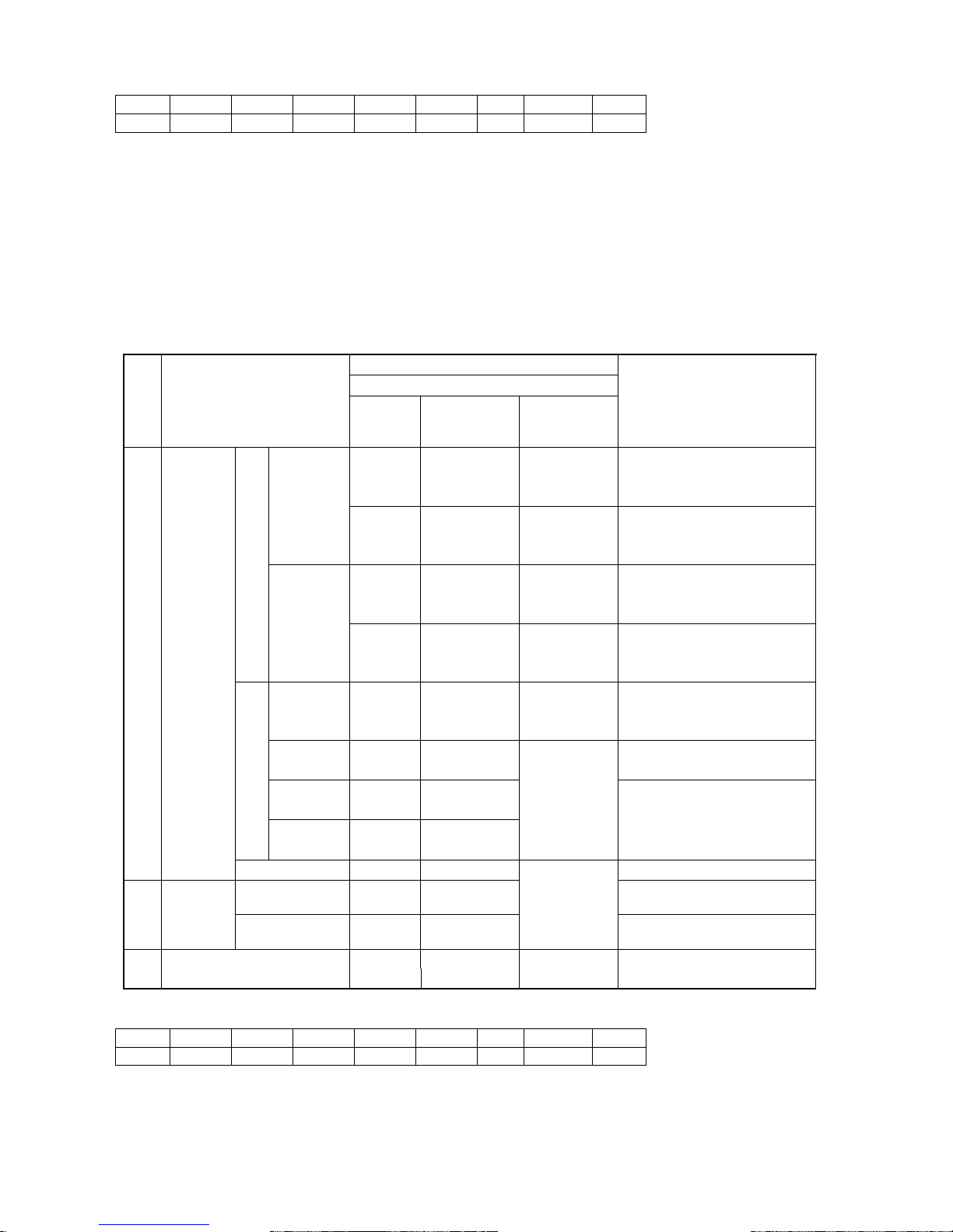
(B) (W) (R) (G) (Y) (Br) (L) (Or) (Gr)
Black White Red Green Yellow Brown Blue Orange Gray
Note 1: The value shown in the above is measured when engine is cold.
Note 2: Instrument used for measurement is a voltage meter for a movable coil type and iron type with
accuracy of 0.5 classes.
Note 3: Color of the lead wires or tapes are shown in
「」.
Note 4: Figures measured by a digital tester are shown in [ ].
Note 5: Output voltage can be adjusted by a voltage adjuster.
6.3 Component Parts Resistance Value
(Ambient Temp.20℃)
Part to measure
Lead Wire
No.
Components/Parts
Code
Color of
Lead wire
(Tape/Cap)
Section
Resistance Value
AU-AV B(R)-B(W)
AV-AW B(W)-B(L)
AW-AU B(L)-B(R)
22mm2 0.014Ω
AU-OA B(R)-B(Gr)
AV-OA B(W)-B(Gr)
A side
AW-OA B(L)-B(Gr)
22mm
2 -
1.25mm2
0.017Ω
BU-BV B(B)-B(Y)
BV-BW B(Y)-B(G)
BW-BU B(G)-B(B)
22mm2 0.014Ω
BU-OB B(B)-B(Br)
BV-OB B(Y)-B(Br)
Welding
B side
BW-OB B(G)-B(Br)
22mm2 -
1.25mm2
0.017Ω
U1-U6 B(R)-B(G)
V1-U6 B(R)-B(G)
3-P 480V
W1-U6 B(R)-B(G)
5.5mm2 0.440Ω
U1-U3
1-P 240V
B(R)-B(L) 0.070Ω
U1-U5
1-P 120V
B(R)-B(L)
V1-V5
Generating
Signal
Line
B(R)-B(L)
5.5mm2-
2.0mm2
0.260Ω
1 Stator
Exciter Coil F-F B-B 0.154Ω
Input Voltage
Adj. Coil
- R-L 4.24Ω
2
Exciter
Stator
Compensation
Coil
- Or-Br
1.25mm2
1.41Ω
- W-W
3
Rotary Solenoid
(for Slow-down)
0.75mm2 3.64Ω
*1:Tighten the signal line wire lead and U2/U3 on the terminal block together.
Always disconnect the CTconnector before you inspect the signal line.
(B) (W) (R) (G) (Y) (Br) (L) (Or) (Gr)
Black White Red Green Yellow Brown Blue Orange Gray
19
Page 23
*2:Connect the power lead terminal for wire feeder into the bottom of the plate controller
located inside of the front control panel.
*3:The magnet switches located besides the terminal board for generator and the welding magnet
switch is located at the plate controller in the back of AC receptacles.
Note: Each coil resistance value should be measured by milli-ohm tester or low resistance
measuring instruments.
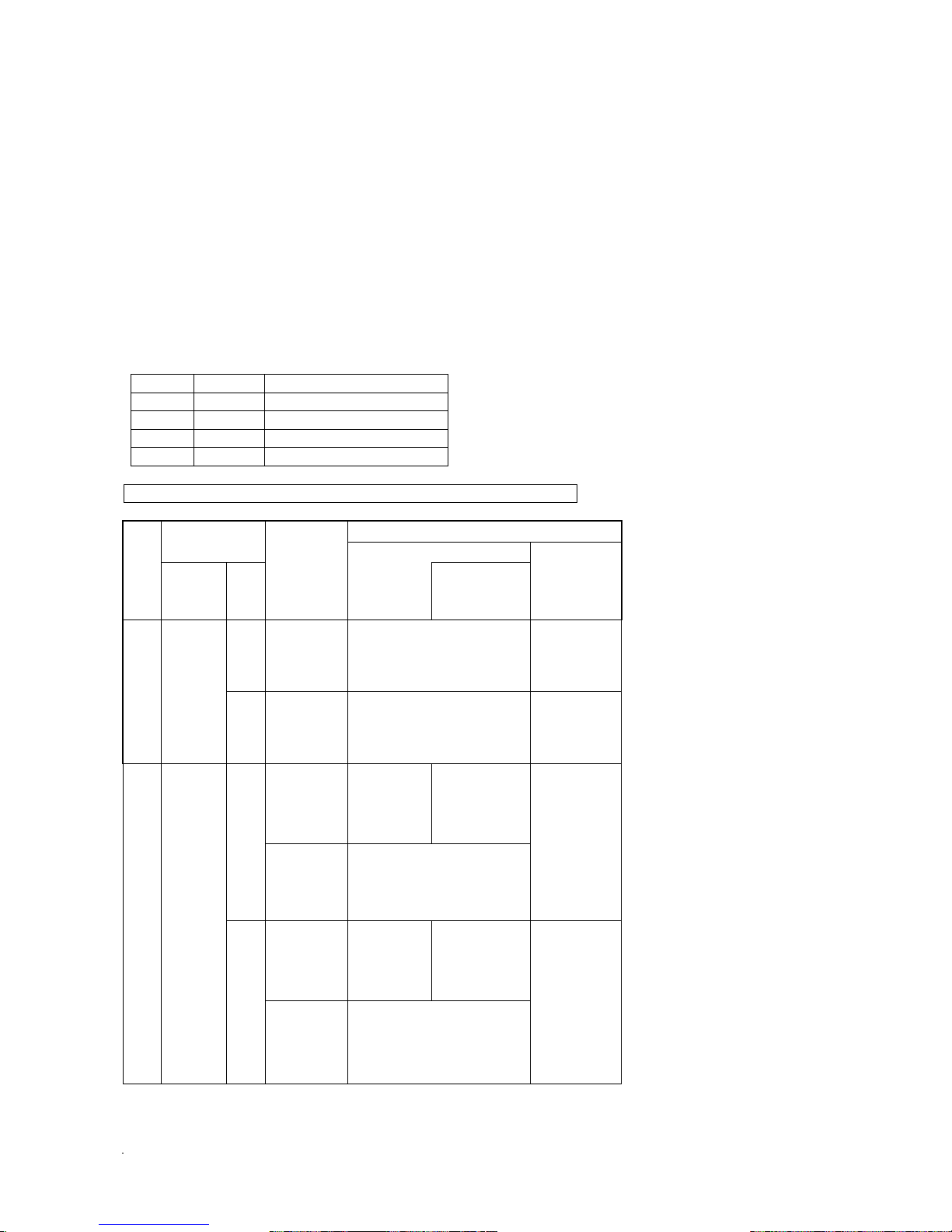
6.4 Display Mode by LED
Position of the output selector switch in the control panel and equipment loaded or no
load is shown by the LED lamp (ON, OFF) combination in the power controller.
<LED Indication>
LED Mode
LED1 Red Single
LED2 Yellow Solenoid
LED3 Green Dual
ED Orange CC/CV Selector Switch
Indication of LED lamps: ○ ON, 《○》BRINK-every 0.5 seconds, ● OFF
LED in the Power Controller
Selector
Switch
No.
Right Left
Slow-down
Switch
No Load
Load
Disconnected
for 8 seconds
Loaded
(Welding &
Generating)
CC
ON/OFF
○ Red
○ Yellow
○ Green
●
《○》 Red
○ Yellow
《○》 Green
●
1 ECO
CV
ON/OFF
○ Red
○ Yellow
○ Green
○ Orange
《○》 Red
○ Yellow
《○》 Green
○ Orange
○ Red
《○》 Yellow
●
ON
○ Red
○ Yellow
●
●
●
CC
OFF
○ Red
●
●
●
《○》 Red
●
●
●
○ Red
○ Yellow
●
ON
○ Orange
○ Red
《○》 Yellow
●
○ Orange
2 SINGLE
CV
OFF
○ Red
●
●
○ Orange
《○》 Red
●
●
○ Orange
20
Page 24

ON
●
○ Yellow
○ Green
●
●
《○》 Yellow
○ Green
●
CC
OFF
●
●
○ Green
●
●
●
《○》 Green
●
● ●
○ Yellow 《○》 Yellow
○ Green ○ Green
ON
○ Orange ○ Orange
3 DUAL
CV
OFF
●
●
○ Green
○ Orange
●
●
《○》 Green
○ Orange
6.5 Power Controller
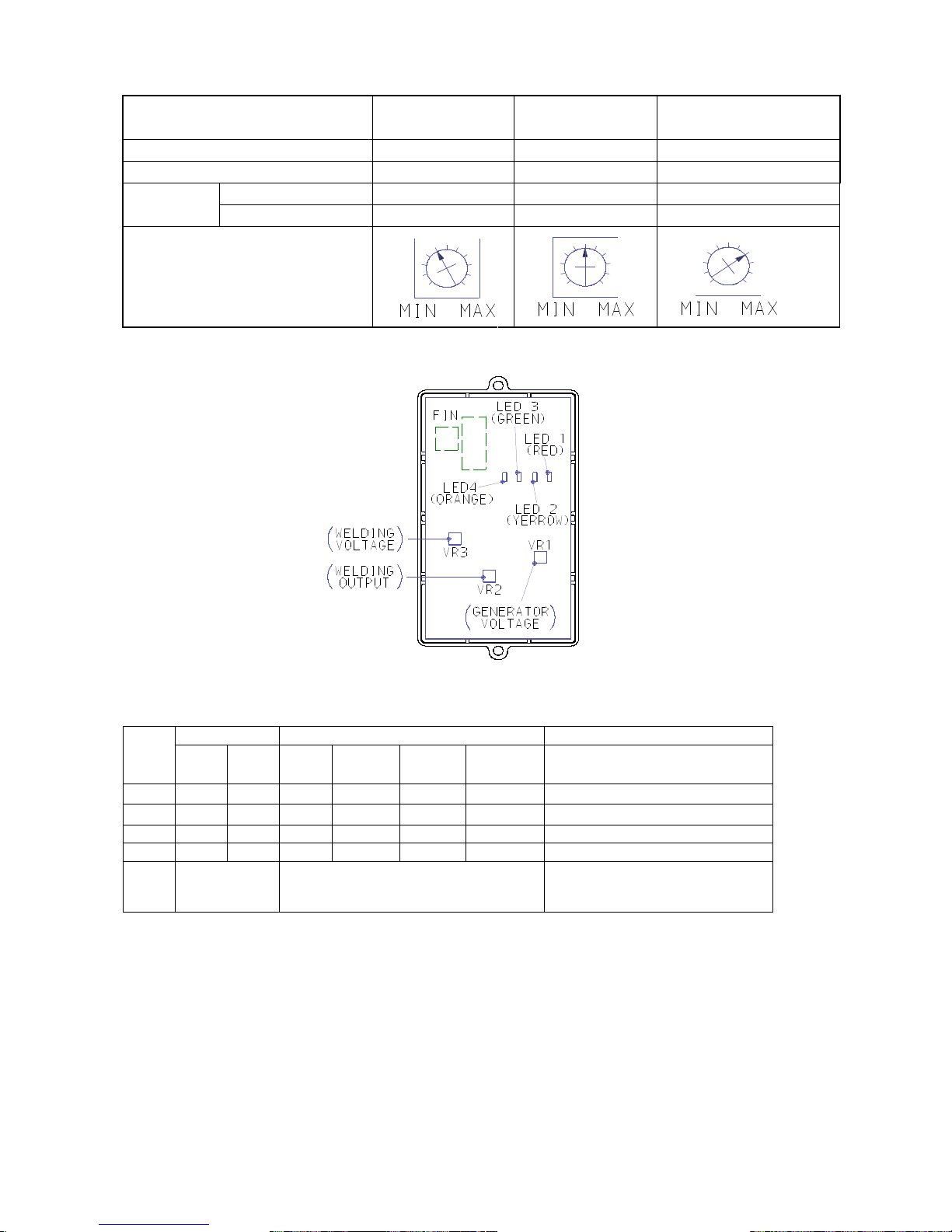
(1) Generating Output Adjustment
Adjust generating output by the volume controller VR1 in the power controller. Refer to a table below.
Adjust the output following the procedure below.
1. Turn the slow-down switch to OFF.
2. Start engine.
3. Adjust voltage at no load to 480V by the voltage adjusting dial in the control panel
according to the value shown in the table below.
(2) Welding Output Adjustment
Welding output should be adjusted by the volume controller VR2 in the power controller. Refer to the
table below.
Follow to the procedure below for the VR adjustment.
1. Turn the output selector switch (right) to Single.
2. Set CC/CV selector switch (left) to CC.
3. Turn A side current adjusting dial clockwise to the end. (maximum)
4. Start engine.
5. Connect the welding load and adjust voltage and amperage by VR2 as per value shown in
the table below.
(3) CV Control Voltage Adjustment
Welding output should be adjusted by the volume controller VR3 in the power controller. Refer to the
table below.
Follow to the procedure below for the VR adjustment.
1. Turn the output selector switch (right) to Single.
2. Set CC/CV selector switch (left) to CV.
3. Turn A side current adjusting dial clockwise to the end. (maximum)
4. Start engine.
5. Connect the welding load and adjust voltage and amperage by VR3 as per value shown in
the table below.
21
Page 25
Generating/Welding
Generating Output
(VR1)
Welding Output
(VR2)
CV Control Voltage
(VR3)
Frequency 60Hz
60Hz
60Hz
Output 3-P 480V
Single, CC
Single, CV
Ampere 14.4A
492A
140A Output
Set Value
Voltage 480V
17V
59V
Common VR Position for reference
(4) Fuse
Fuse Monitor Engine
No
10A 50A
Water
Temp
Oil
Press.
Battery
Charge
Pre-heat
Starter Switch
Run➔Start
1
○
○
●
○
○
●➔○
Normal
2
●
○
●
●
●
●➔○
Starter motor does not rotate
3
○
●
●
●
●
●
Starter motor does not rotate
4
●
●
●
●
●
●
Starter motor does not rotate
Ref.
Fuse Condition
○: Normal
✕: Cut-Off
Monitor Display
○: ON
✕: OFF
Note: After the starter switch is turned to operation, the lamp shows ON for few second.
(5) Protection Feature
When a temperature of the welding output control component(s) is exceeded, the output is
automatically reduced to protect the component(s). An “OVERHEAT” lamp is also ON and flickered.
When AC output is not available, follow the procedure below.
Note: Stop operation immediately if such case may happen until the overheat lamp will turn off.
When this case may repeat, reduce duty cycle or current to be used.
2
2
Page 26
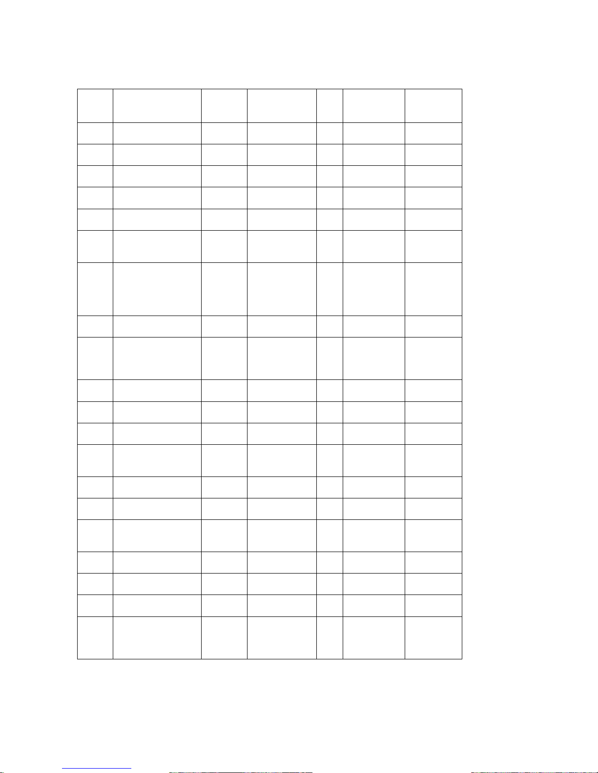
7. Tightening Torque
No Nomenclature
Part to
be
tighten
Size Qty
Torque
Allowance
Nm(kgf/cm)
Reference
1 Exciter Stator Bolt M5x45 4
3.0-4.9
(30-50)
2
Rear Bracket
(Main Stator)
Bolt M12x160 4
29.5-32.3
(300-330)
3 Generator Stator
Bolt,
Shim
M10x30 8
19.7-24.5
(200-250)
4 Rotor Bolt M10x1.25x30 4
40.7-49.5
(415-505)
7T
5 Fan
Bolt,
Shim
M8x25 6
9.9-14.7
(100-150)
6
Front Bracket
(Alternator Assy
to install
Bolt M10x1.25x25 8
40.7-49.5
(415-505)
7T
7 Engine Stay Bolt M10x1.25x25 8
28.5-34.3
(290-350)
Small Head
(Opposite
Side
Distance
14)
8
Thyristor
(Stuck Fin)
Screw,
Shim
M6x20 4
2.5-3.4
(25-35)
9
Thyristor, Rectifier
(Terminal Side)
Bolt,
Shim
M5 18
2.5-3.4
(25-35)
Thyristor
and
Rectifier
Attached
10 Socket
Drain
Plug
M12x1.25x13 3
39.3-49
(400-500)
11 Flexible Tube
Flange
Nut
M8 6
17.7-21.5
(180-220)
12
Terminal Rest
(Welding Terminal)
Nut M10 4
17.7-21.5
(180-220)
Brass
13
Terminal Post
(100V Terminal)
Nut M6 8
2.5-3.4
(25-35)
Terminal
Post
Accessory
14
Resistor
(Heater Terminal)
Nut M5 8
2.2-2.7
(22-28)
Resistor
Accessory
15
Magnetic Switch
(Wiring)
Nut M8 1
9.9-11.7
(100-120)
Engine
Accessory
16
Battery
(Terminal
Attachment)
Nut M8 2
5.0-6.0
(50-62)
Battery
Accessory
17
Battery
(Wiring)
Nut M8 2
6.9-8.8
(70-90)
Battery
Accessory
18
Glow Plug
(Terminal)
Nut M4 1
1.0-1.7
(10-18)
Engine
Accessory
19
Oil Pressure
Switch
Bolt,
Shim
M4x8 1
1.4-1.9
(14-20)
Engine
Accessory
20 Fuel Strainer Bolt M8x65 1
17.7-21.5
(180-220)
Opposite
Side
Distance
12
23
Page 27
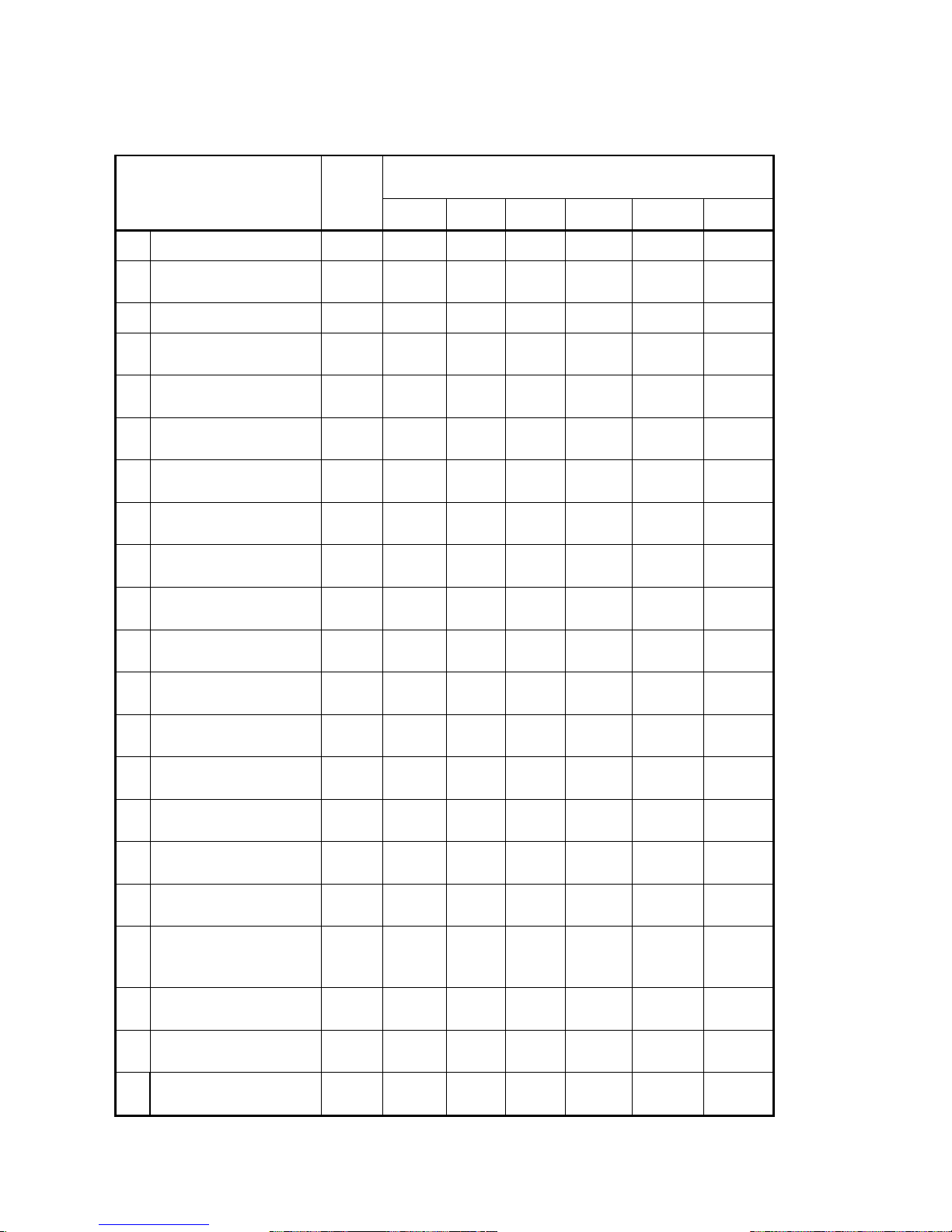
7.1.1 Periodical Check for Engine
●Consult Kubota Service Dealer ○User Check ◎Replace Parts
Checking interval
Items
Start up
Check
At
50hrs
Every
100hrs
Every
200hrs
Every
400hrs
Every
1000hrs
Every
2000hrs
1 Check and Supply Fuel
○
2
Check and Supply Engine
Oil
○
3 Change Engine Oil 1st ◎ 2nd ◎
4 Oil Filter Change
1st ◎
2nd ◎
5 Check/Add Coolant
○
6 Coolant Change
○ or 2
years
7 Clean Fuel Filter
1st ○ 2nd ○
8 Change Fuel Filter
◎
9
Drain Water/Clean Fuel
Tank
○
10
Check Leakage Fuel, Oil,
Water
○
11 Check/Add Battery Liquid
○
12 Clean Air Element
1st ○ 2nd ○
13 Change Air Element
◎
14 Adjust tension V-belt
1st ○ 2nd ○
15 Change V-belt
◎ or 2
years
16 Clean Radiator Fin
●○
17 Clean Radiator inside
●○
18
Change Fuel Hose, Oil
Hose,
Vibration-absorbing
Rubber
◎ or 2
years
19
Adjust Engine Valve
Clearance
●
Adjust
●
Plane
20
Check/Adjust Injection
Nozzle
●
21
Check/Adjust Injection
Pump
●
24
Page 28
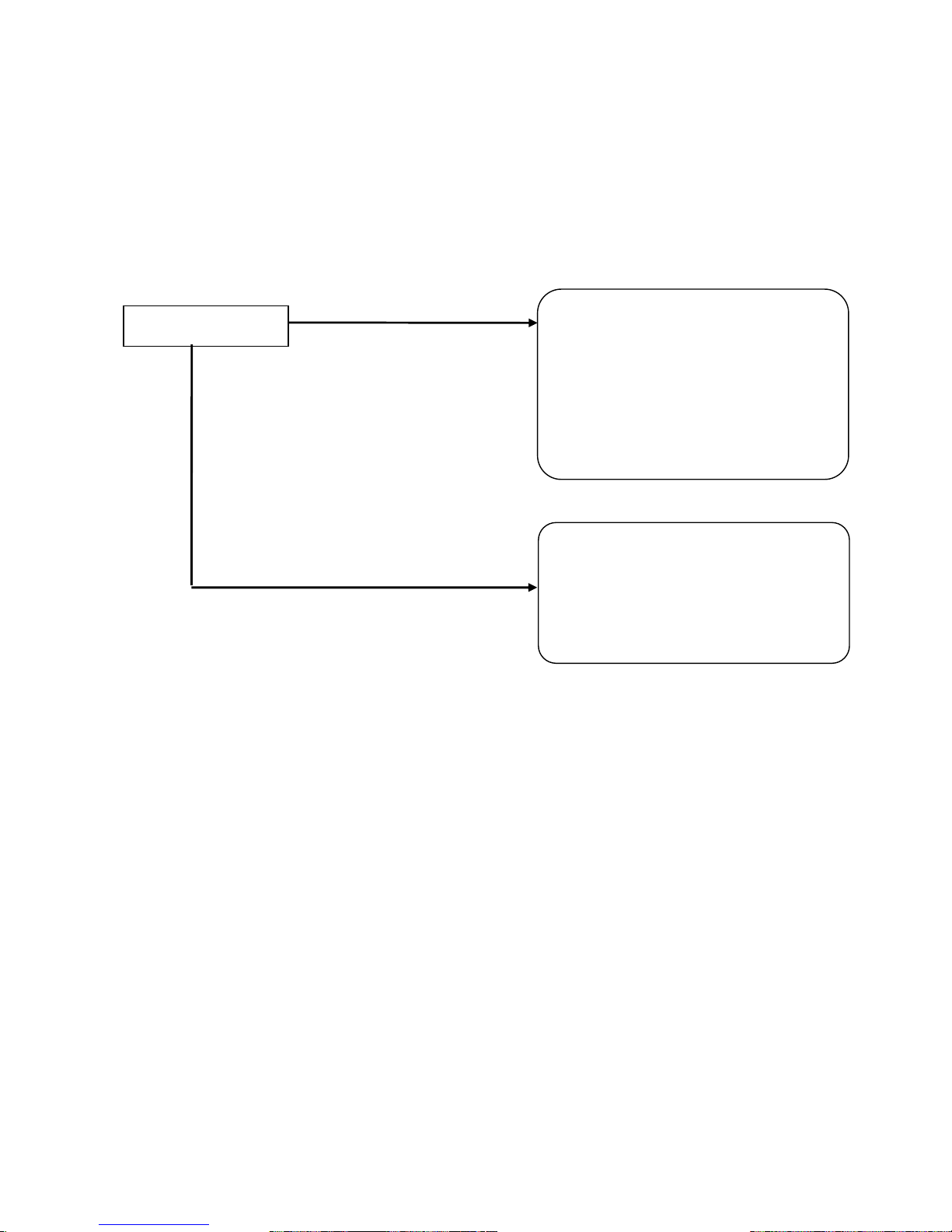
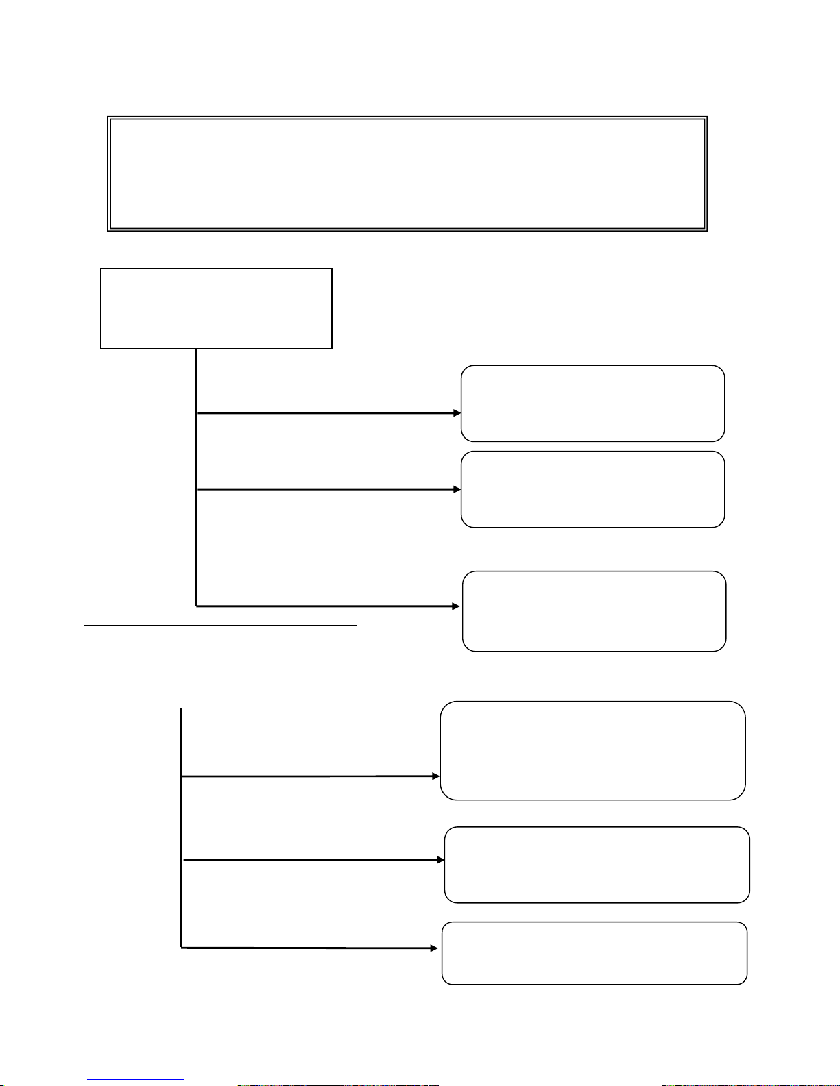
8. Trouble Shooting
<Pre-check> Always check the volume of oil, coolant, and fuel before processing to trouble
shooting.
8.1 Engine won’t start
<Pre-check> Always check oil, coolant and fuel volume before processing to trouble shooting.
YES
Starter Motor works
Dead Battery
Damaged Starter Motor
Damaged Starter Switch
Burnt 20A Fuse
Burnt 50A Fuse
Lead wire disconnected or poor contact
Damaged Engine (Burned-down)
Damaged Emergency Relay
Short-circuited lead wire
Damaged Engine
(Nozzle, Injection Pump,etc.)
NO
25
Page 29
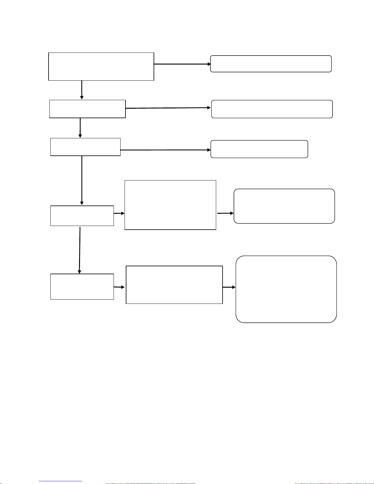
8.2 Weak Arc
YES
NO
NO
<High idle>
82V+/-3V
<Eco>42.0+/-2V
* Refer to “Service Data”
Change Power Controller
Change speed control Motor for
Speed Adjustment
Turn Current Adjusting Dial clockwise
Welding Cable
Use proper size and length of cables
Simultaneous use with
Generat
or Output
Stop using Generator Output
Check Engine
Speed at no load
<Slow/Eco>
2100±20
min
-1
<Regular Speed>
3600±20
min
-1
No Load Welding
Output Voltage
Stator Damaged
Thyristor Damaged
Rectifier Damaged
PCB Damaged
(Power Controller)
Resistor Damaged
Lead wires/connectors are
poorly contacted
Check position of switch and dial
Current Adjusting Dial
2
6
Page 30
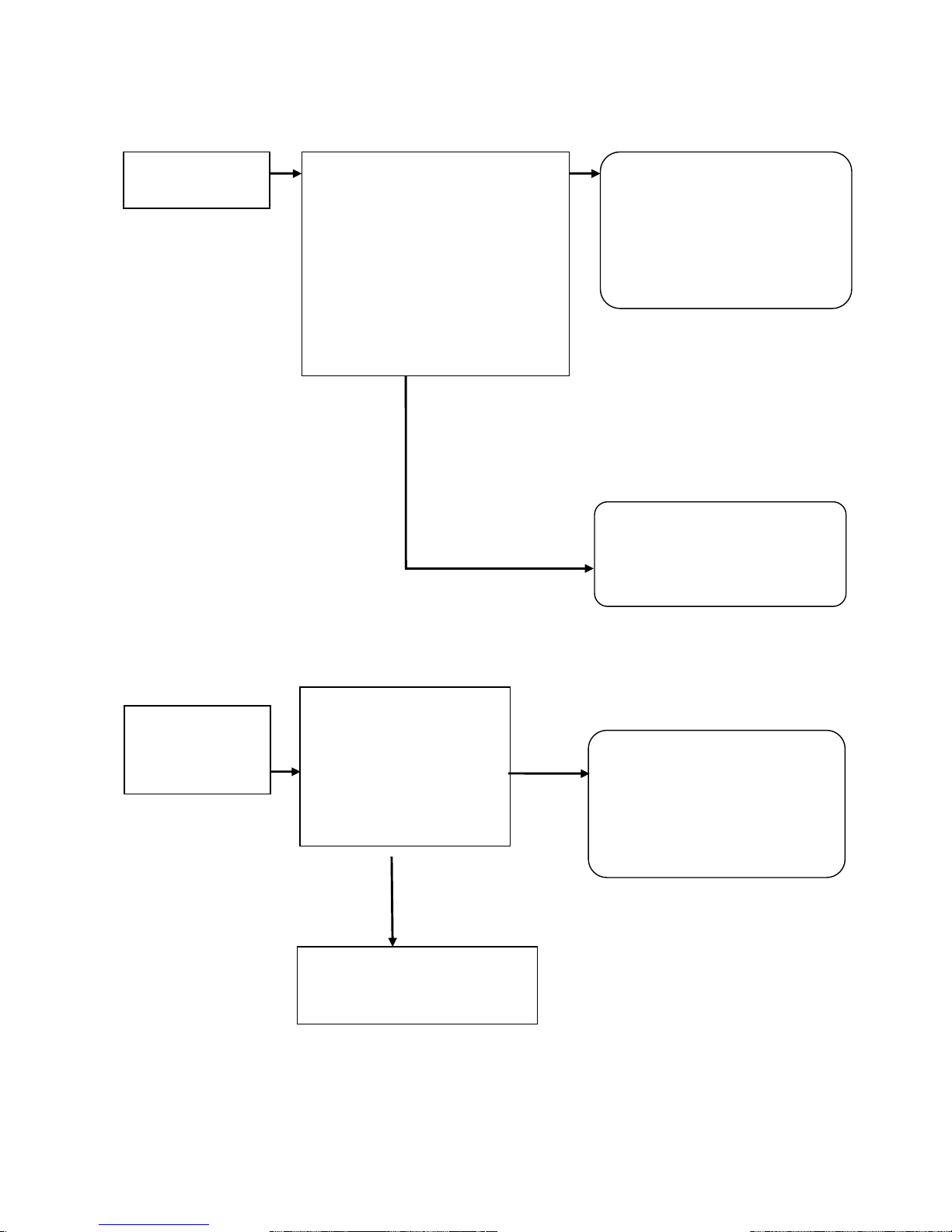
8.3 No Welding Arc
No
(Low)
8.4 No AC Output
Welding Output
Coil Voltage
Welding Output Coil Voltage
Remove Lead Wires and measure
AU-AV, AV-AW, AW-AU:35V
AU-OA, AV-OA, AW-OA:20V
BU-BV, BV-BW, BW-BU:35V
When values displayed are as
per the page “output voltage (at no
load)”, the rotor and stator are
normal. Refer to the page “Output
Voltage (at no load)
”
.
Thyristor Damaged
Rectifier Damaged
Damaged PCB
(Main Controller)
Damaged Resistor
Weak contact of lead wires and
connector
Rotor Damaged
Stator Damaged
Initial Exciter Circuit Damaged
Refer to Resistance Value
NO
AC Output Coil
Voltage
(Measure at
Terminal Rest)
<Breaker at ON position>
<Regular Speed 3-Phase>
480V
<Regular Speed 1-Phase>
245V
Refer to “Output Voltage (at
no load)”
Rotor Damaged
Stator Damaged
Initial Exciter Circuit/Coils
Damaged
Refer to the page “Component
Parts Resistance Value”
Terminals/Receptacle Damaged
Breaker Damaged
Led Wire Damaged
YES
27
Page 31
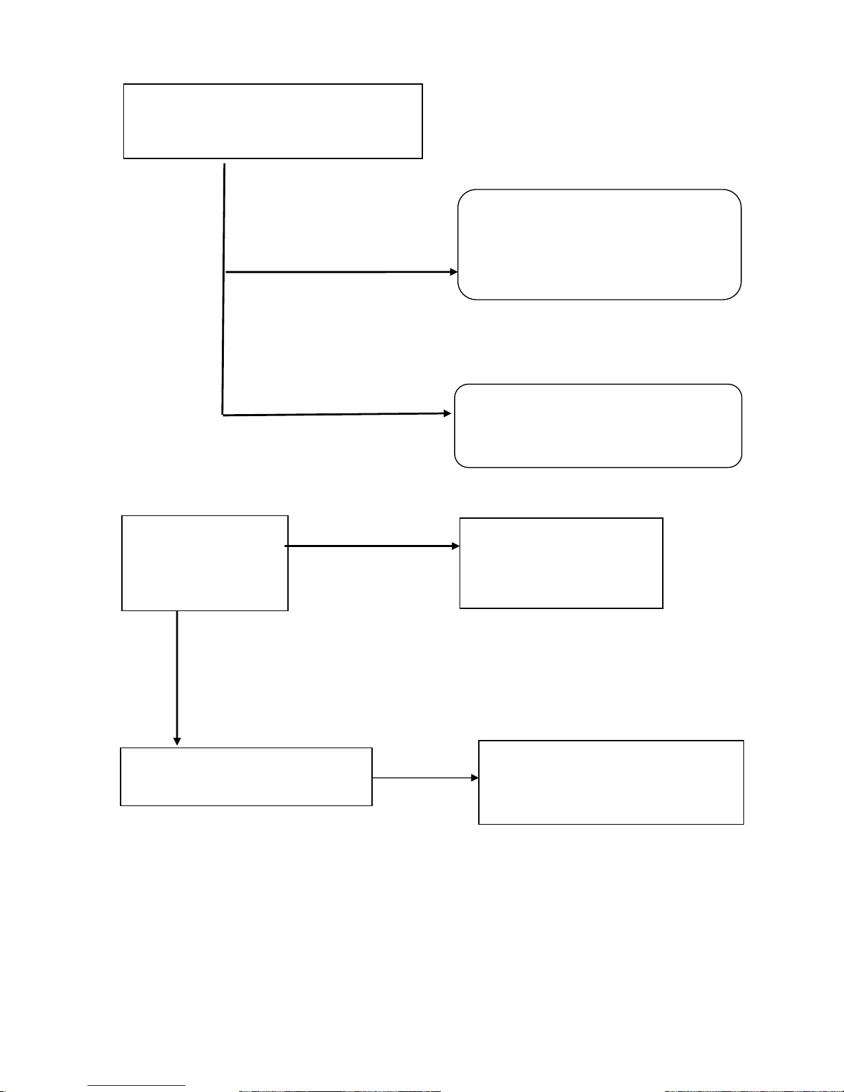
8.5 Check Rotor, Stator and Exciter Circuit
Exciter Voltage low but current high
Exciter Voltage high but current low
【Phenomenon】
No voltage energized at all or extremely low voltage
1. Check Initial Exciter Circuit
Compensate Coil on Exciter Stator
(Orange~Brown)
Refer to the voltages
Exciter Rectifier Damaged
Exciter Resistor Damaged
Lead wire or Connector Poorly Contacted
Exciter Stator Compensate-Coil
Damaged (Broken) Coil Resistance
1.41Ω
Refer to “Component Parts Resistance
Value”.
Exciter Stator Compensate-Coil
Damaged (Broken) Coil Resistance
1.41Ω
Refer to “Component Parts Resistance
Value”.
Both Exciter Voltage and Amperage low
Damaged Rotor
Damaged Stator
Exciter Circuit Damaged
Note: To measure resistance on coil, Milliohm Tester is necessary. Multipurpose Tester cannot
be used due to too large fudge factor.
Both Exciter Voltage and Current Low
Exciter Voltage high but Amperage
low
Exciter Voltage low but Amperage
high
2. Check Magnetic Field Circuit
Voltage Adjusting Coil of Exciter Stator
(Red-Blue)
Refer to the voltages
Power Controller Damaged
Rectifier Damaged
Exciter Stator Voltage Adjust. Coil Damaged
(Coil Resistance 4.24Ω)
Rotor Damaged
Exciter Stator Voltage Adjust. Coil Damaged
(Broken)
(Coil Resistance 4.24Ω)
Exciter Stator Voltage Adjust. Coil Damaged
(Short-Circuited)
(Coil Resistance 4.24Ω)
28
Page 32
8.6 Auto Idle won’t work
3. Check Rotor and Stator
Measure output voltage at each coil on stator
Refer to the voltages
Rotor Damaged
(Coil Broken or Rectifier Damaged)
In Case 3-P Voltage reads 315V (Rated
480V), one rotor coil (out of 2) broken or
Rectifier on rotor damaged
AC Output Voltage each equally
low
AC Output Voltage each unbalanced
Rectifier on rotor Damaged
Thyristor Damaged
Stator Damaged (Short-circuit, Broken, etc)
Refer to the resistances value.
When turning auto idle
Switch to high idle,
Engine turns at high
speed
Damaged Switch
Damaged Printed Circuit
Disconnected Lead Wires
or Connectors
The speed does not step into regular
though welding or generating is
applied.
CT for Welding Damaged
CT for Generating Damaged
Printed Circuit (Power Controller)
Damaged
Lead Wires or Connectors Damaged
29
Page 33
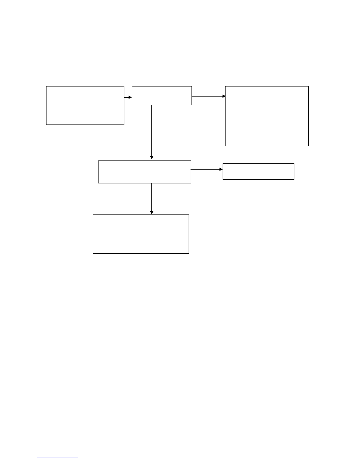
8.7 Engine Speed won’t return to idle
<Caution> Be sure to make operation check within a few seconds while the circuit may be
short-circuited in this case. (Measure and judge short-circuit currents on welding side and
generating side within a few seconds) Otherwise the stator should be burned.
NO
Engine won’t return to
idle.
Switch is selected AUTO
or .ECO.
Check Welding and
Generating Voltage
Short circuit Rectifier for
welding
Short-circuit Thyristor for
welding
Short Circuit Breaker
Short Circuit Lead Wires or
Connectors
YES
Check conductivity at contact
point on idle control switch.
(No Conductivity at contact point)
Switch Damaged
Printed Circuit Damaged
Lead wires or connectors on Slowdown Switch Broken.
Speed control Motor for Speed
Adjustment Damaged.
YES
30
Page 34
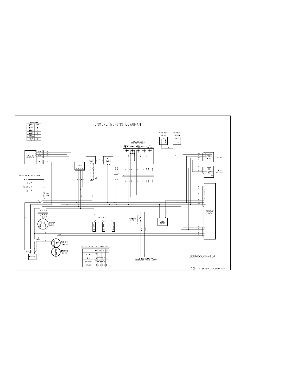
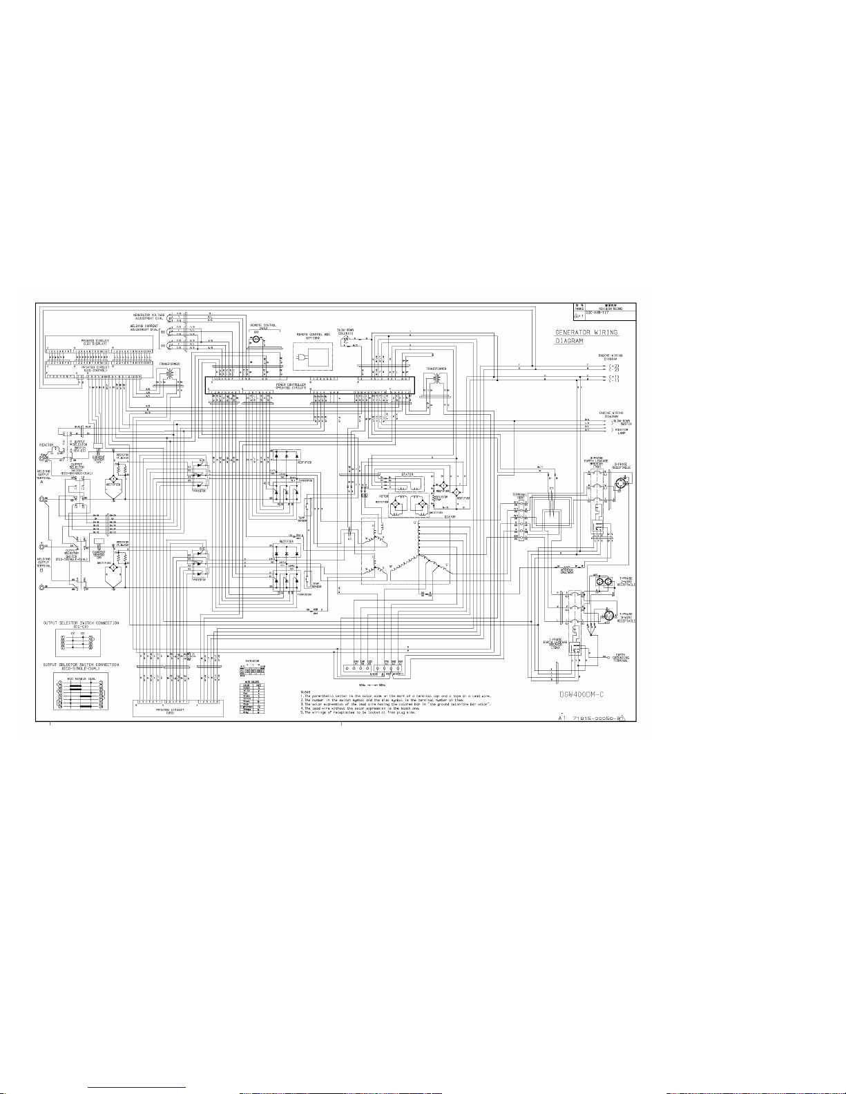
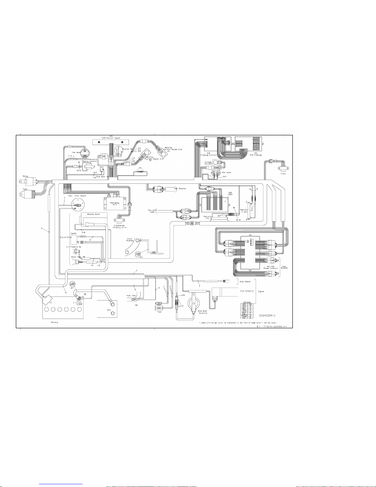
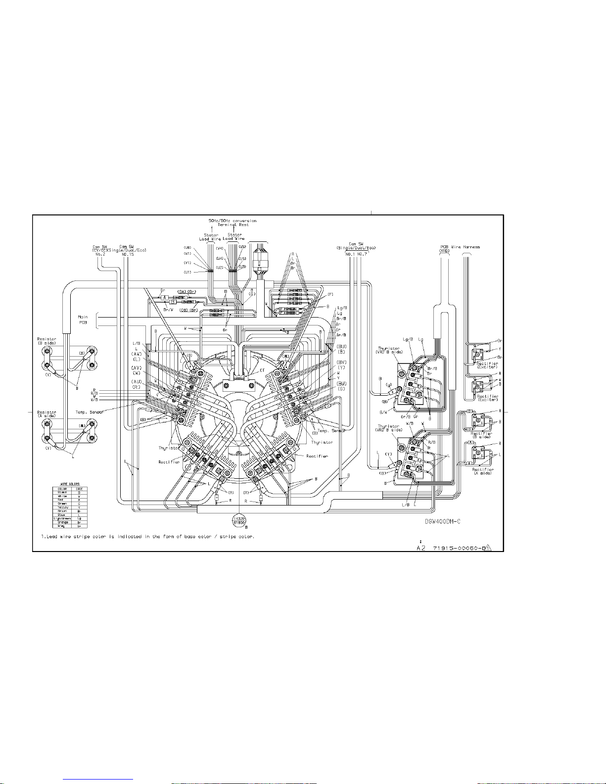
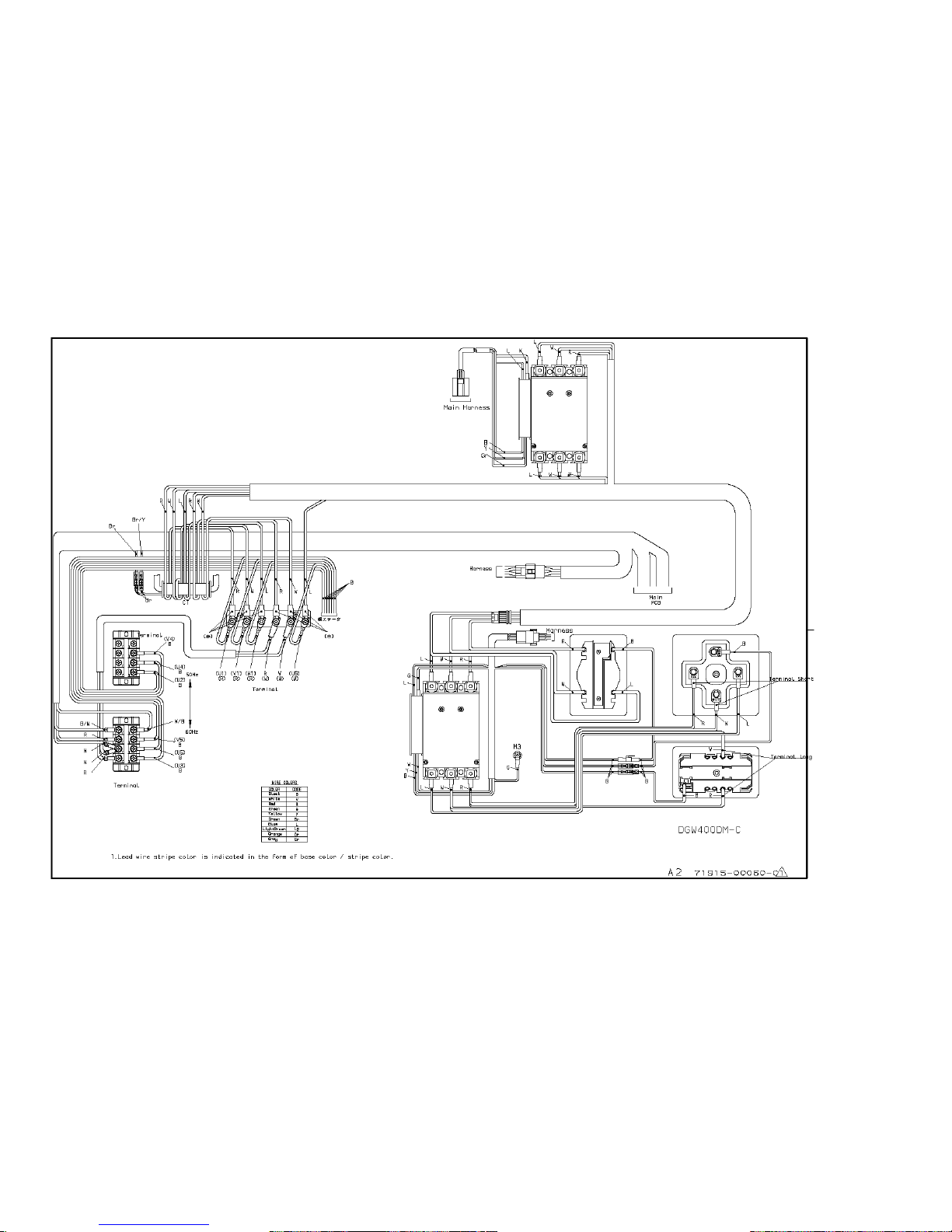
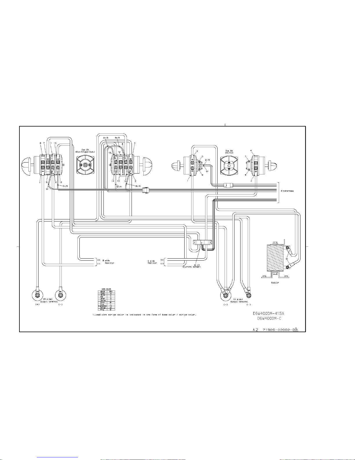
9. Wiring Diagram
9.1 Generator Wiring Diagram
31
Page 35
32
Page 36
33
Page 37
34
Page 38
35
Page 39
36
Page 40

HIMOINSA POWER SYSTEMS, INC.
16002 West 110th Street
Lenexa, KS 66219-1312
Tel: 913-495-5557 | Fax: 913-710-2988
Toll Free: 866-710-2988
www.hipowersystems.com
 Loading...