

Clutch Type Torque Auto Control
CL-Series
CL-2000, CL-3000, CL-4000,
CL-6000, CL-6500 and CL-7000
(NL-Series and Push-to-Start Type)
SS-Series
SS-2000, SS-3000, SS-4000,
SS-6500 and SS-7000
(Push-to-Start Type)
α
-Series
α
-4500, α-5000 and α-6500
(Push-to-Start Type)
ESD Type
•
Q-CR-ESD Type •Q Type
Electric Screwdrivers
and Power Supply
Operation Manuals
(September, 2015)
HIOS Inc.
111-6, Akiyama, Matsudo City, Chiba, Pref. Japan
TEL. 81-47-392-2001 FAX. 81-47-392-7773
15
A
Operation Manual No.ET-A002
Utilizing 100% post-consumer
recycled paper pulp
1
Thank you for your purchasing a Hios screwdriver.
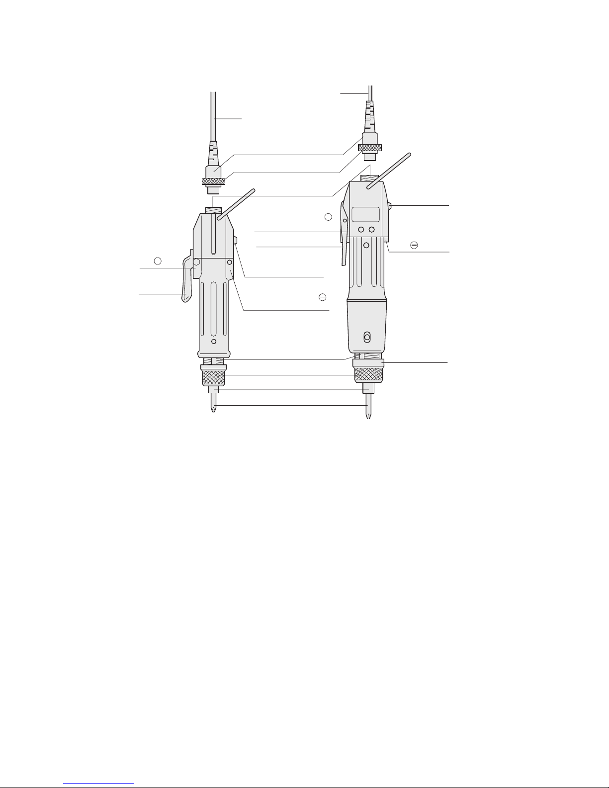
1. Name of Parts
2. Accessories:
•
Bits
•
Torque adjusting spring
•
Carbon brushes
cord
cord
Joint ring
Connector
Torque adjusting nut
Joint shaft collar
Bit
Detachable cord
(5P both ends common)
Adjusting bolt
(Torque adjusting scale)
Forward/Reverse
switch
Carbon
brush
cap
Switch
lever
Carbon brush cap
Switch lever
Carbon brush cap
Carbon brush
cap
Driver scale
Forward/
Reverse
switch
+
+

2
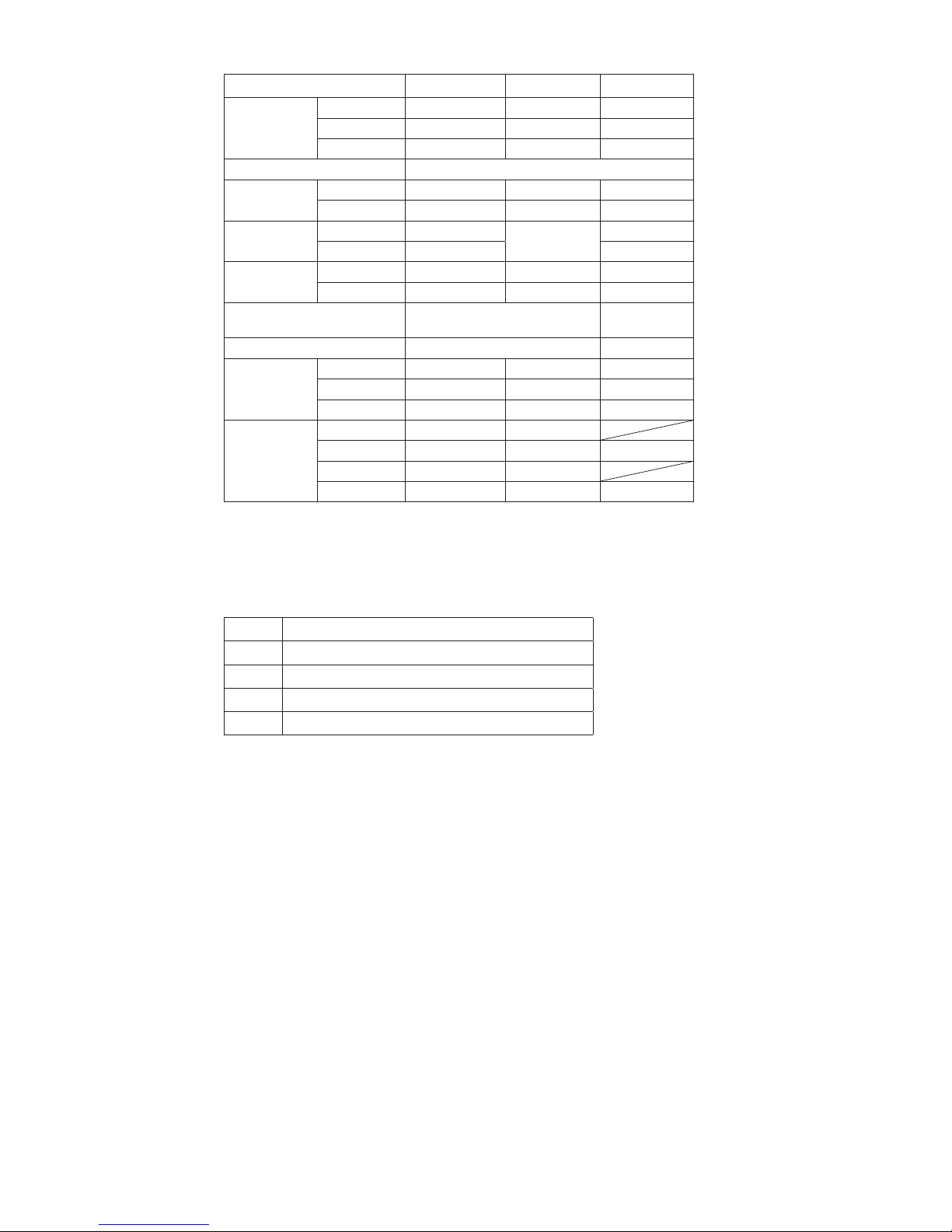
3. Specications
CL-Series
(NL-Series, ESD, Q-CR-ESD, Q, PS-Type)
Model CL-2000 CL-3000 CL-4000 CL-6000 CL-6500 CL-7000
Output
Torque
Range
N.m 0.02
-
0.2 0.03 - 0.2 0.1 - 0.55 0.2 - 1 0.3 - 1.6 0.3 - 2.5
lbf.in 0.17
-
1.7 0.3 - 1.7 0.9 - 4.8 1.7 - 8.8 2.6 - 14 2.6 - 22
(kgf.cm) (0.2 - 2) (0.3 - 2) (1 - 5.5) (2 - 10) (3 - 16) (3 - 25)
Torque Switching Stepless Adjustment
Unloaded
Rotation Speed
(r.p.m)
HI 680 1000 1000 800 900 750
LOW 490 670 690 500 600 500
Screw Size
(mm)
Small Size
Screw
1.0 - 2.3 1.0 - 2.0 1.4 - 2.6 2.0 - 3.0 2.0 - 4.0 2.0 - 5.0
Tapping
Screw
1.0 - 2.0 1.0 - 1.7 1.4 - 2.3 2.0 - 2.6 2.0 - 3.0 2.0 - 4.0
Dimensions
(mm)
Grip Diameter
∅
26
∅
32.5
∅
32.5
∅
37
∅
37
∅
37
Total Length
166 183 197 220 235 255
Bit Type Hios H4
Hios H4 or
1/4 Hexago-
nal
Hios H5 or 1/4 Hexagonal
*1
Weight (g) 200 350(390) 380(430) 600(600) 660(660) 750(750)
Length of
screwdriver
cord (see
the table of
attached cord
reference)
Standard 1.5m(5p) 1.5m(5p) 1.5m(5p) 2m(5p) 2m(5p) 2m(5p)
CL-ESD A A A A A A
CLQ-CR-ESD
B B B B B B
CLQ C C C D D D
*2
Power
Supply
CLT-45
○ ○ ○ ○ ○
CLT-60
○ ○ ○ ○ ○ ○
CLT-100
○ ○ ○ ○ ○
MC-70L
○ ○ ○ ○ ○ ○
SS-Series
(ESD, Q-CR-ESD, Q, PS-Type)
Model SS-2000 SS-3000 SS-4000 SS-6500 SS-7000
Output
Torque
Range
N.m 0.02 - 0.2 0.03 - 0.2 0.1 - 0.45 0.25 - 1.3 0.3 - 2
lbf.in 0.17 - 1.7 0.3 - 1.7 0.9 - 3.9 2.2 - 11 2.6 - 17.4
(kgf.cm) (0.2 - 2) (0.3 - 2) (1 - 4.5) (2.5 - 13) (3 - 20)
Torque Switching Stepless Adjustment
Unloaded
Rotation Speed
(r.p.m)
HI 680 1000 1000 900 750
LOW 490 670 690 600 500
Screw Size
(mm)
Small Size Screw
1.0 - 2.3 1.0 - 2.0 1.4 - 2.6
2.0 - 3.0 2.0 - 4.0
Tapping Screw
1.0 - 2.0 1.0 - 1.7 1.4 - 2.3
Dimensions
(mm)
Grip Diameter
∅
26
∅
32.5
∅
32.5
∅39 ∅39
Total Length
166 183 197 235 255
Bit Type Hios H4
Hios H4 or 1/4 Hexagonall
Hios H5 or 1/4
Hexagonal
*1
Weight (g) 200 350(390) 400(450) 660 750
Length of
screwdriver
cord (see the
table of attached cord
reference)
Standard 1.5m(5P) 1.5m(5P) 1.5m(5P) 2m(5P) 2m(5P)
SS-ESD A A A A A
SSQ-CR-ESD
B B B B B
SSQ C C C D D
*2
Power
Supply
CLT-45
○ ○ ○ ○
CLT-60
○ ○ ○ ○ ○
CLT-100
○ ○ ○ ○
MC-70L
○ ○ ○ ○ ○
*1
: Numeric data in ( ) is weight of push-to-start driver.
*2
: Circles (○) indicate that the power packs can be used with the respective tools.
3
α
-Series
(ESD, Q, PS-Type)
Model
α
-4500
α
-5000
α
-6500
Output Torque
Range
N.m 0.4 - 0.8 0.4 - 1.2 0.5 - 1.8
lbf.in 3.5 - 7 3.5 - 10 4.3 - 16
kgf.cm 4 - 8 4 - 12 5 - 18
Torque Switching Stepless Adjustment
Unloaded Rotation
Speed (r.p.m)
HI 1700 1000 1700
LOW 1200 700 1200
Screw Size
(mm)
Small Size Screw
2.0 - 3.0
2.0 - 3.0
3.0 - 4.0
Tapping Screw
2.0 - 2.6 2.6 - 3.0
Dimensions
(mm)
Grip Diameter
∅
32.5
∅
32.5
∅
37
Total Length
207 207 235
Bit Type Hios H4 or 1/4 Hexagonal
Hios H5 or 1/4
Hexagonal
*1
Weight (g) 440 (490) 660 (660)
Length of screwdriver cord (see the
table of attached
cord reference)
Standard 1.5m(5p) 1.5m(5p) 2m(5p)
α
-ESD A A A
α
-Q C C D
*2
Power
Supply
CLT-45
○ ○
CLT-60
○ ○ ○
CLT-100
○ ○
MC-70L
○ ○ ○
*1
: Numeric data in ( ) is weight of push-to-start driver.
*2
: Circles (○) indicate that the power packs can be used with the respective tools.
Due to the high rotating speed, the tightening torque of α-series screwdrivers may differ
from the setting depending on the screw or board materials being used.
●
Reference of attached cord for drivers
Type Attached Cord
A 2m Cord ESD Type (5P)
B 2m Cord ESD Type (5P) & Iinclude ESD Vinyl tube
C 1.5m Cord Type (5P) & Iinclude Vinyl tube
D 2m Cord Type (5P) & Iinclude Vinyl tube
Precautions on Use
(1) Do not drop it or otherwise subject it to excessive
shock.
(2) Be careful not to splash water or oil.
(3) Use HIOS power supplies units. We are not respon-
sible for any malfunctions or troubles caused by using
power units other than specied.

4
4. How to Operate
1. Select bit. Push down the joint shaft collar at the top
of the screwdriver and insert the bit.
2. See the torque chart and match it with you torque application.
3. Select correct spring by color for corresponding torque
according to the torque chart.
Example:
For getting automatic shutting at 8 kgf.cm with CL-
6500 you could use either spring Y or W. With Y
spring the torque adjusting nut should be set at #3
position on the driver scale; with W spring at #5. For
torque over 11 kgf.cm, however, only Y spring is applicable as can be seen on the chart.
4. Plug in the power supplies and check red power indicator. If it is not on, check fuse on power pack or AC
supply.
5. Connect the cord of driver to power supplies. Make
sure groove on plug lines up with projection on socket.
Tighten knurled ring.
6. Set torque adjusting nut at proper position on driver
scale conferring with torque chart.
7. For testing purpose, drive one screw until driver stops
automatically.
8. Check the fastened degree of the screw with a torque
wrench. (For this checking, HIOS torque meter HDP
or HDM Series recommended.) If found too high or
too low, adjust the position of nut for further testing.
9. Once you get best result keep Nut there intact and
you will enjoy accurate repeatability of fastening at
same torque.
10. The torque adjusting nut of CL-6000, CL-6500, CL7000 may be locked after the position is determined.
Holding Torque Adjusting Nut, rotate only the metal
band around it until a tapped hole is uncovered. Install a M3 x 3 set screw there and tighten it. Return
band to original position.
● The torque adjusting nuts of the CL-2000, CL-3000,
CL-4000 can be locked by aligning the red mark on
the outer casing with any one of two vertical grooves
(or three grooves for the standard-type screwdriver) of
the bolt located nearest the torque adjusting scale. To
change the position, lift and turn the nut outer casing.

5
● The CL-2000 (SS-2000) Electric Screwdriver have
‘Double nut system’ (Nut xing ring and Torque adjusting nut) to avoid loosening from shock or vibration to
the driver. To adjust those two nuts, follows ①to
③
steps below.
At rst, stop the Nut xing ring upper
surface to t the graduation, if you
want to adjust.
Then turn the Torque adjusting nut so
as to push up the Nut xing ring.
Lastly, to avoid the loosening of the
‘Torque adjusting nut’ strongly fas-
ten the Nut xing ring’ by holding the
‘Torque adjusting nut’.
5. Push-to-Start Type
Both the models of Driver have Push-to-Start type that is
designed to start by causing a proper thrusting pressure on
the bit in place of pressing the Switch Lever by the fore-
nger. Drivers of this type are identied by the additional
sign PS following the principal Push-to-Start type models.
The PS type, therefore, has no lever for starting. All other
functions remain same as the principal type.
Usersofthistypeisspecicallycautionedtodisconnectthecord
to shut off power when handling the Quick Change Collet for
replacing bit to avoid danger from surprising starting.
6. Power Supplies
The power pack for CL Drivers requires two basic functions: (1) to convert local AC power to lowered DC Power
and (2) to shut off the power by automatical reaction to the
pulse emitted from the Driver at the moment the torque at
work reaches the regulated limit. The function (2) can be
performed, if so opted, by a ready-made unit called Control
Box CB-105 installed separately from the unit for the function (1).
①
②
③

6
CLT-45
Connects to one CL, SS or
α
-series driver. (except the CL-
7000, SS-7000,
α
-6500, CL-9000
model).
CLT-60
Connects to one CL, SS or
α
-series driver. (except CL-9000
model).
CLT-100
Connects to two CL, SS or
α
-series driver. (except the
α
-6500, CL-9000 model).
■
Specications
Power Pack Model CLT-45 CLT-60 CLT-100
Size (mm)
71.5x146x42.6
(H)
88x210x52 (H) 182x145x132 (H)
Weight (kg) 0.33 0.83 4.0
Input
AC 100 -240V
± 5%
47/63 Hz
AC 100 -240V
± 5%
47/63 Hz
AC 100V, 12 0V
or 220-240V
± 5% 50/60 Hz
Output Voltage
LOW/HI LOW/HI LOW/HI
AC Cord Length 1.8 m
CLT-60
CLT-100
CLT-45

7
■
Max. number of connected drivers:
Type max. number of drivers Note
CL-2000, 3000, 4000
SS-2000, 3000, 4000
20 pcs.
Each driver must be connected
to CB-105 (Control Box ).
CL-6000, 6500, 7000
SS-6500, 7000
α
-4500, α-5000
10 pcs.
α
-6500
5 pcs.
■
Specications
Power Pack Model MC-70L
Size (mm)
320x220x153 (H)
Weight (kg)
12
Input
AC 100V, 120V or 220-240V 50/60 Hz
Output Voltage
LOW/HI
AC Cord Length
1.8 m
Accessories Trunk-line wire 20 m 1 line (Black and Red)
Branch-line wire 0.5 m 10 lines (Black and Red)
U-Element 20 pcs. #560B
■
Control Box
CB-105
(SUB)
Control boxes for cutting off and supplying current in response to
clutch action of drivers. Each driver should be connected to one
control box.
■
Specications
Size (mm) 70x42x100 (H)
Weight (g) 240
Input Cord Length (m) 2
Attachment Plates 2 pieces
MC-70L
(requires separate control box)

8
7. How to connect a control Box
● There are two pairs of output terminals, two (+) and
two (-), on the back of the body case. They are provided to divide main wires to two directions from the
main unit. When distributing the power pack in one
direction only, keep one pair of the terminals idle.
● When connecting main wires to the terminals, be
sure to connect the red wire to (+) and the black wire
to (-).
1. Connect the branch wire to the main wire at regular
intervals. Use a U-Element for connection. You can
connect wires without stripping off the wire coating.
2. Insert the main wire ① into the groove by widening
the lower split (opening) of the U-Element.
3. Fully insert the branch wire ② into the upper hole until
it stops.
4. Insert a U-shaped element ③ (the comb-shaped
metal part) with a pair of pliers to make it ush with
the plastic body. Only the coating is broken; both
wires still connected.
5. Put an insulation cover ④ on the element and snap it
shut.
6. The connected branch wires have plug receptacles
at their other ends. Connect the control box plugs to
these plug receptacles.
Branch wire
U-shaped element
Trunk-line
wire
Do not strip
coatings.
Insulation cover
①
②
③
④

9
8. How to replace carbon brushes
1. It is recommended to replace the pair of carbon
brushes to maintain performance when worn out to
about half the length.
2. Carbon brush caps have a slot.
Unscrew them with a at tip driver
to open them. Be careful not to
allow the carbon brush inside to
jump out as it is kept there under
spring pressure.
3. With the mini-type screwdriver,
one of the carbon brush covers
is located under the switch lever,
therefore, the switch lever must be
removed before reaching it. Turn
the hexagonal head of the axis
supporting the switch lever, then
they can be removed.
4. Replace the worn carbon brushes with new pair. Note
that the end surface of the carbon piece is not exactly
at but of slightly concave face, so see to that the
carbon piece is placed in the correct direction when
inserted into the holder to have its curved face make
smooth meeting with the rotation of the deep inner
commutator. Screw the cap tightly.
Control box
CB-105 (SUB)
Power pack
MC-70L
Black
Red
Branch
Trunk line wires
wires
Black
Red
CB-105
(SUB)
•
U-Element
Parts No.: MCLK-560B
•
Branch wire
Parts No.: RED: MCCBS-RD
BLACK: MCCBS-BK
•
Trunk-line wire
Parts No.: RED: MCCBM-RD
BLACK: MCCBM-BK
CONCAVE

10
0.9
0.8
0.7
0.6
0.5
0.4
0.3
0.2
0.1
1234 56
CL-4000
R
0.05
0.1
0.15
0.2
0.25
0.3
1234 56
N.m N.m
CL-3000
BL
G
0.05
0.03
0.02
0.1
0.15
0.2
0.25
1234 5678
N.m
CL-2000
B
Y
0.05
0.03
0.02
0.1
0.15
0.2
0.25
1234 5678
N.m
SS-2000
B
Y
1
0.5
1
1.5
2
2.5
234
5
6
CL-6000
N.m N.m N.m
Br
1
0.5
1
1.5
2
2.5
23456
CL-7000
P
Y
1
0.5
1
1.5
2
2.5
2
34 56
CL-6500
Y
W
0.5
0.4
1234 56
0.6
0.7
0.8
0.911.1
1.2
1.3
α-5000
(Gr)
α-4500
(W)
N.m
Gr
W
N.m
1
0.5
1
1.5
2
2.5
23456
α-6500
Y
N.m
Color of spring
Torque adjusting scale
0.1
0.05
0.03
0.3
0.2
0.5
0.45
0.4
123 456
SS-4000
N.m N.m
R
0.1
0.05
0.03
0.3
0.2
0.5
0.4
123 456
SS-3000
N.m
G
0.5
1
1.5
2
123456
SS-6500
(Dashed line)
SS-7000
(Solid line)
Y
P
BL
BL
BL
Color of Spring
B: Black
BL: Blue
G: Gold
R: Red
Br: Brown
Y: Yellow
W: White
P: Purple
Gr: Green
■
Proper guidance on output torque (at HI input)
CL-series
(NL-Series, ESD, Q-CR-ESD, Q, PS-Type )
SS-series
(ESD, Q-CR-ESD, Q, PS-Type)
α
-series
(ESD, Q, PS-Type)
* Since α-series screwdrivers feature high-speed rotation,
their tightening torque may differ from the setting values
depending on the various conditions of screws and parts
materials.
 Loading...