

HIOS VZOP-STC Instruction Manual
Power Supply with Screw Counter
VZOP-STC
Instruction Manual
(March 2009)
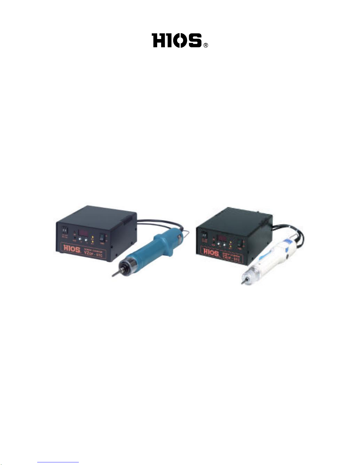
For VB-OPC screwdriver For VZ-OPC screwdirver
Hios Inc.
111-6, Akiyama, Matsudo, Chiba Pref. Japan, 270-2223
TEL: +86(Japan)47-392-2001
FAX: +86(Japan)47-392-7773
09A Operation Manual No.ET-A009

2
Outline of the VZOP-STC
When performing work that requires screws to be tightened with an electronic screwdriver,
the operator must check that the correct number of screws has been used for a particular
piece of work in order to prevent the work piece leaving with screws that have not been
tightened.
The VZOP-STC screw counter makes use of the OP output signals (normal rotation signal,
torque up signal, reverse rotation signal) from the screwdriver to allow the operator to check
if any screws require tightening.
The VZOP-STC features a power source (DC 24 V / 0.3 A) to power external equipment as
well as an input/output signal to control them. As such, the unit can be connected directly to
an interlocking solenoid valve to prevent careless mistakes made by the operator.
(When using a jig that prevents removal of the work piece before the all screws are fully
tightened)
The operator can also select a function that reverses (increases) the count if a reverse
signal is input to the screwdriver to loosen the screws (selected with mode SW3).
Another option allows the reverse count up time to be set when screws are biting (normally
not counted). This time can be set between 0.2 and 1.0 seconds. A switch has been
installed on the internal circuit board to allow the normal operator to change the settings.
The factory default setting is level 2 (0.2 seconds) (level 1 cannot be used).
Note: Changing the settings can be dangerous. Only change settings after removing the
power plug.
The SET signal is set when power is supplied to the unit, meaning that it is possible to
provide effective management that is not reliant on the operator during cell production
when one operator is required to uses several screwdrivers. The ER BZ output signal
warns of the presence of incomplete work when the work check switch is OFF. The unit
may be reset or the signal will be output until the work is completed. This signal can be
used by attaching a warning buzzer to warn the operator.

3
VZOP-STC Specifications
Input voltage : AC 100 V ±5% 50/60 Hz
Power capacity : 100 W
Fuse capacity : 6 A / 250 V (with one spare fuse)
Dimensions : 160 (W) x 175 (D) x 84 (H)
Weight : 1.5 Kg
AC cord length : 1.8 m (with ground)
Supplied accessories : 8 terminals, 1 slotted screwdriver
Compatible drivers : VB-OPC specification driver
VB-1510-OPC
VB-1820-OPC
VB-3012-OPC including PS type
VB-4504PS-OPC
VZ-OPC specification driver
VZ-1510-OPC
VZ-1820-OPC
VZ-3012-OPC
Including PS type
VZ-4506-OPC

4
Please read through the electronic screwdriver instruction manual carefully before
use and use only as per instructions.
- Installation area
1. Always install a ground leakage breaker and safety breaker to commercial power
supplies.
2. Install the unit in an area that is not subjected to dust, dirt or metal fragments.
3. Install the unit in an area that is not subjected to water or oil.
4. Do not place heavy items on top of the unit or stack units on top of one another.
5. Select a safe installation area that is free from vibration.
6. If the unit is to be installed in an elevated location, ensure that it is fixed firmly so that
there is no danger of the unit falling.
7. Do not install the unit near other high-voltage equipment or electronically noisy
environments.
8. Do not use input and output cables that are longer than required or knot them. Doing so
may result in incorrect reading.
- Precautions for use
1. Ensure that the unit is grounded and that the specified rated power and voltage are used.
2. Ensure that loads connected to the output terminals on the rear panel terminal block do
not exceed the rated load.
3. If external equipment connected to the +DC 24 V output terminal or input/output
terminals on the rear panel terminal block are affected by the electromagnetic induction
of relays and solenoid valves coils, noise prevention in the form of reverse voltage
absorbing diodes should be used. Equipment may operate incorrectly or malfunction if
noise prevention is not used.
4. Do not connect the +24 V DC terminals on the rear panel terminal block to any output
terminal or GND terminal.
5. If the unit’s functions are used to power external equipment with an external power
source, a common GND terminal should be used. Equipment may operate incorrectly or
malfunction if a common GND is not used.
6. Do not provide additional voltage to the input or output terminals. Additional voltage will
result in a malfunction.
7. Use the unit in temperatures of 5°C to 40°C and 80% or less humidity (with no
condensation).
8. Always hold the plug when connecting or removing the power cord or driver cord.
9. Do not pull the cords, drag them across oil or sharp edges, or place heavy objects on top
of them. Doing so may result in severed wires or malfunctions.
10. If a malfunction occurs and the unit overheats or the fuse blows, stop using the unit
immediately and turn off the main power switch, remove the power cord from the power
outlet and bring the unit to our service department.
 Loading...