

HIOS HSV-10RB, HSV-12RB, HSV-17RB, HSV-20RB, HSV-23RB Instruction Manual
...
Automatic Screw Feeder
Neji Taro
V for Automatic Assembly
HSV-RB series
HSV-10RB HSV-12RB HSV-14RB
HSV-17RB HSV-20RB HSV-23RB
HSV-26RB HSV-30RB
Instruction Manual
Read this manual before using this device.
Current as of April 2018
18A
Manual No. ET-D005
HIOS Inc.
1-16-5 Akiyama, Matsudo City, Chiba Pref., Japan
TEL: +81-47-392-2001 FAX: +81-47-392-7773

- 1 -
Contents
1. OVERVIEW OF Neji Taro V
for Automatic Assembly Type ...... 1
2. BEFORE USE ......................................................... 1
3. OPERATING PRECAUTIONS ................................. 2
4. NAMES OF MACHINE PARTS ............................... 5
5. ADJUSTMENTS AND CHECKS BEFORE USE ...... 6
6. PARTS ADJUSTMENTS AND REPLACEMENTS ... 12
1. OVERVIEW OF Neji Taro V for Automatic Assembly Type
Thank you very much for selecting our Automatic Screw Feeder “Neji Taro V for Automatic Assembly Type”.
This machine can line up screws (Type M1-M3) and supplies them one by one to increase the efciency of screwing work.
Different sizes of screws can be used by changing the rail, escaper, passing plate and the robot escaper guide.
It can be used wherever there is a power source for an AC adapter.
2. BEFORE USE
Please check for the following accessories before operating the machine.
*CD-ROM 1
*AC adapter 1 unit *Hexagonal wrench 1 piece
*Screwdriver 1 piece (For adjusting timer)
*Ground wire 1 piece
7 . APPLICATION WITH ROBOTIC SYSTEM ............. 22
8 . MISCELLANEOUS .............................................. 24
9 . TROUBLESHOOTING ........................................... 25
10. SPECIFICATIONS ................................................. 31
11. EXTERNAL FEATURES DIAGRAM ...................... 33
12. REPAIR CLAIM SHEET ...................................... 34
13.
THE FOLLOWING TABLE IS FOR CHINA RoHS2
35

- 2 -
3. OPERATING PRECAUTIONS
This manual contains safety alert symbols and signal words to help prevent injuries to the user or damage to property.
◎
Indications
This indicates there is a chance of death, serious injury or re if the instructions are not
followed.
This indicates there is a chance of personal injury or damage to property if the instructions are not followed.
◎
Symbols indicating type of danger and preventative measures
Prohibited from doing. Never do this!
Do not disassemble, modify or repair.
Do not touch with wet hands.
This indicates to stop operations.
Unplug power supply from wall outlet.
General caution.
WARNING
CAUTION

- 3 -
WARNING
Do not disassemble the AC adapter as there is a risk of electric shock, re or malfunction.
Do not damage, alter or change the power cord. Do not place heavy objects on the cord.
Do not pull hard on the cord or twist the cord as it could be damaged, thereby causing a risk of re or electric shock.
Do not handle the AC adapter with wet hands as it could cause an electric shock.
When using an outlet with AC100-240 V, don’t overload the electrical circuit.
Do not modify or remodel this machine as this may cause a re or electric shock.
Do not operate this machine near ammable liquids, gasses or materials as there could be a risk of re or explosion.
Stop operating the machine and unplug the AC adapter from the wall outlet when you detect overheating,
smoke, a pungent odor or any other unusual condition, as there may be a risk of re or electric shock. Contact
the dealer, from which you purchased the machine and have it examined and repaired.
In the case of a thunderstorm, stop operating the machine, turn off the power and unplug the AC adapter from the wall
outlet. If there is lightning and thunder nearby, move away from the machine and do not touch it or the AC adapter.
After the thunder stops, and when it is safe to do so, check the machine.
If there is any abnormality, contact your dealer.
Attachment of the earth wire
When the earth wire is connected loosen the screw near the
mark once.
After inserting the U-shaped metal tting of an attached cable, tighten the screw again.
the bottom of the main body

- 4 -
CAUTION
Use only the AC adapter supplied with this machine otherwise it may result in a re or electric shock.
Do not install this machine in an unstable location otherwise it may fall causing damage or injury.
Always operate the machine with the upper cover in place, otherwise it may result in injury.
Do not allow any foreign material to enter the machine while in operation.
Do not put your ngers into the machine while in operation, otherwise an injury will result.
Do not operate this machine in overly humid or dusty conditions.
Keep the plug socket clean at all times otherwise it may cause a re or electric shock.
When moving the machine, always disconnect the AC adapter from the wall outlet or it may result in damage to
the cord, or cause a re or electric shock.
Turn off the machine and unplug the AC adapter from the wall outlet during closing hours or if the machine will
be unused for any extended period of time.
When performing maintenance, changing parts or when you sense an abnormality in the machine, turn the power off and pull the AC adapter from the wall outlet.
Do not operate the machine with tension on the AC adapter cord. Keep the cord loose and untangled.
Do not bend, alter or damage the rail. Do not apply any oil. It is recommended that the user clean the rail periodi-
cally.
Do not use any screw that is out of the specied range nor any screw that is oily or dirty.
When extracting screws, do not exert excessive force or shock to the screws.
Upper cover
Scooping chamber
Rail xing bolt
Attaching plate
of the holding
plate
Holding plate
Light-emitting sensor
Light-receiving sensor
Power switch
Front cover
Rear cover
Left side
cover
Right side cover
Rail
Escaper
Passing plate
Brush
DC jack
Signal out put
jack
Timer knob
Vibration adjusting bolt
(under the machine)
Scooping block left
and right
(moving up
and down)
Vibration adjusting plate
xing bolt
LED Screw sensor
Escaper guide
for the robot
Sensor bracket attaching bolt
Escaper bracket
installing screw
Holding plate attaching bolt
Rear cover
xing screws
(2-left/2-right)
- 5 -
4. NAMES OF MACHINE PARTS
5. ADJUSTMENTS AND CHECKS BEFORE USE
5-1. Checking the model number of the main body
Check if the machine has the parts which match the nominal diameter of the
screws to be loaded. Check the model number of the rail, escaper, escaper
guide for the robot and passing plate by referring to the following table. Each
escaper is stamped with a model number which matches with the type of
screws that can be used. The escaper guide for the robot is stamped with a
model number which corresponds with the types of screws that can be used.
Screw feeder
model
Screw
size
Rail model
No.
Escaper model
No.
Escaper guide of
the robot model No.
Passing plate
model No.
HSV-10RB M1.0 HSV-RI-10
HSV-7017-10
HSV-TPO00610-1 HS3-02052-1
HSV-12RB M1.2 HSV-RI-12
HSV-7017-12
HSV-14RB M1.4 HSV-RI-14
HSV-7017-14
HSV-17RB M1.7 HSV-RI-17
HSV-7017-17
HSV-20RB M2.0 HSV-RI-20
HSV-7017-20
HSV-TPO00610-2 HS3-02052-2
HSV-23RB M2.3 HSV-RI-23
HSV-7017-23
HSV-26RB M2.6 HSV-RI-26
HSV-7017-26
HSV-30RB M3.0 HSV-RI-30
HSV-7017-30
Note: Screws, with a different nominal diameter, can be used by replacing the rail, escaper, passing plate
and the robot escaper guide for the robot. The parts, for replacement, are available separately .
Before delivery, each section of the machine is checked and adjusted with panhead screws matching the nominal diameters of
the ordered model. Most screws may be usable in the initial status of adjustment however, if the height or shape of the screw
head is different or if the operation is regarded as abnormal, each section must be readjusted. If this is the case, make the following checks and adjustments:
○ Check the screw load amount ○ Check and adjust the brush ○ Check and adjust the passing plate
○ Check and adjust the rail vibration ○ Check and adjust the holding plate
○ Check and adjust the front & rear sides of the rail ○ Check and adjust the timer
If the rail, escaper, passing plate and robot escaper guide are replaced, screws with a different nominal diameter can be accept-
ed. After these parts are replaced, ne adjusting is required. The respective adjusting procedures will be described elsewhere.
Please read these procedures.
Rail
identification
seal
Passing plate iden-
tication seal
Escaper
identication
stamp
Escaper guide
for the robot
identication
stamp
- 6 -
Loaded screws
Screws, loaded into the chamber, must not be above the rail-groove
surface. (The maximum screw load must be 2-3mm below the railgroove surface.)
This inclined surface, on both the right and left inclined plates, should
be visible.
Power switch
Turn On and Off the power switch
to put the brush bristles in a horizontal position.
Power switch
Move the brush by hand to check
that the screws, in the rail groove,
are in slight contact with the brush
bristles and make adjustments if
necessary.
Brush
Brush height adjusting bolt
Brush assembly attaching screw
Passing plate
The brush must not be in
contact with the passing
plate when it moves.
- 7 -
5-2. Amount of screws to be loaded
An excessive amount of screws, loaded into the chamber, will have an
adverse effect on the screw alignment and transport. The gure, shown
at right, indicates the maximum amount of screws to be loaded. Use
this as a guide when loading the screws.
・
Turn the power switch ON and OFF so that the scooping block is at the
lower limit position.
・
Load screws up to approximately 2-3 mm below the rail surface.
・
At this time, check that screws are not loaded so as to cover the upper
portion of the inclined plate.
・
Be sure to determine the screw load by observing the machine while it is
in operation.
5-3. Checking and adjusting the brush
Turn OFF the power supply before checking and adjusting.
Load the screws into the scooping chamber, turn ON and OFF the
power switch so that screws are aligned into the rail groove.
・
Turn ON and OFF the power switch so that the brush bristles are in a
horizontal position as shown in the gure at right.
・
Check that the heads of the screws, in the rail groove, are in slight con-
tact with the brush bristles.
・
When the brush height is too high or low, this will have an adverse effect
on the screw alignment and transport.
・
If any adjustment is necessary, loosen the brush height adjusting bolt to
adjust the brush height.
・
If the plastic portion, at the front of the brush, comes into contact with the
passing plate, loosen the brush assembly mounting screw and make an
adjustment either backward or forward.
・
Operate the machine to check that the brush operation is normal.
Passing plate
Loaded screw
Passing plate
attaching bolt
Half-press
(provided on both
sides of the passing plate)
The clearance should be just enough to permit the loaded screws
to pass through the passing plate.
Weaker
vibration
Vibration adjusting
plate xing bolt
Vibration
adjusting
bolt
The rail must not come in contact with the escaper.
The clearance must not be too large.
Stronger
vibration
- 8 -
5-4. Checking and adjusting the passing plate
Turn OFF the power switch before making any checks or adjustments.
・
Check that the passing plate is adjusted to a height that permits lo aded
screws to pass just within the clearance limit.
・
If the passing plate is too low, screws cannot pass.
If the passing plate is too high, it will hamper a smooth transport of the
screws.
・
If adjustment is required, loosen the passing plate attaching bolt and ad-
just the height.
・
After making an adjustment, do an operational check.
Note: Using the half-presses on both sides of the passing plate as guides,
slide the passing plate up or down.
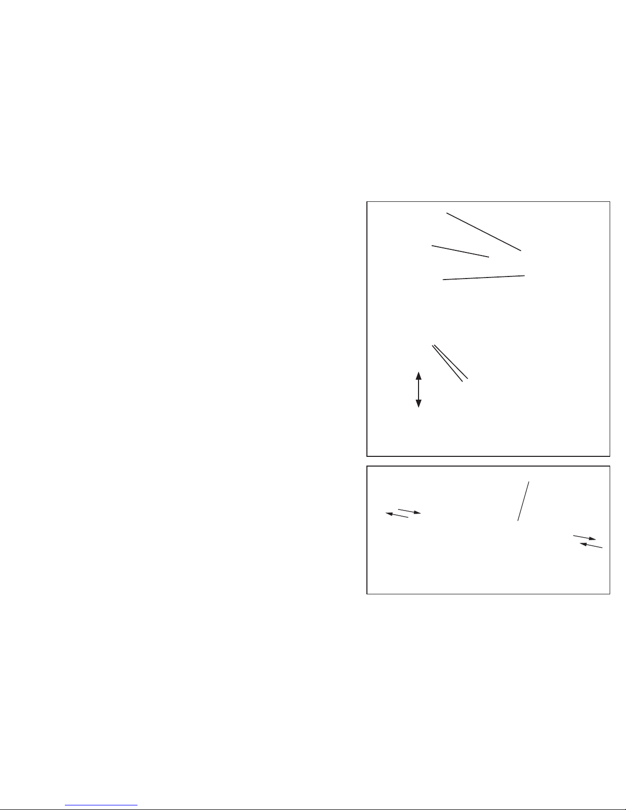
5-5. Checking and adjusting the rail vibration
This machine’s rail vibration can be adjusted.
The screw transport speed differs depending on the screw type.
Check the screw transport speed. If the rail vibration hinders a smooth
transport of the screws, it can be adjusted.
・
Loosen the anti-vibration screw at the rear of the machine.
Next, turn the vibration adjusting screw, located on the bottom of the ma-
chine, to adjust the vibration.
When the screw is turned clockwise, as viewed from the bottom of the
machine, the vibration will increase.
When the screw is turned counterclockwise, the vibration decreases.
・
If the vibration is adjusted to a too large a value to increase the transport
speed, the rail will hit against the escaper and screws may fall into the
machine from the clearance, failing to unload screws normally. Adjust the
vibration to a proper value that matches the loaded screws.
(Related item: Check and adjust the front and rear positions of the rail.)
・
After making an adjustment, be sure to tighten the anti-vibration bolt.
・
After making an adjustment, do an operational check.
The clearance between screws loaded in the rail and the
holding plate should be 0-1mm.
Holding plate
Loaded screw
Holding plate
attaching screw
Up/down
adjustment
Rail xing bolt
Adjust the rail either
backward or forward.
Escaper
The holding plate must
not make contact with
the escaper.
- 9 -
5-6. Checking and adjusting the holding plate
Check the position of the holding plate.
・
Check that the clearance between screws in the rail groove and the
holding plate is about 0-1mm.
・
If there is no clearance, a screw will be caught. If the clearance is too
large, a screw pile or screw jump will occur.
・
If any adjustment is required, loosen the holding plate attaching screw
and move the plate up or down.
・
If the holding plate makes contact with the escaper, it will affect the
smooth operation of the escaper movement.
・
After making an adjustment, check the machine operation.
5-7. Checking and adjusting the front/rear positon of the
rail
If the rail comes into contact with the escaper, or the clearance between the rail and escaper is too large, when the machine is operated,
loosen the rail xing bolt and adjust the rail either backward or forward.
After making an adjustment, be sure to tighten the rail xing bolt.
・
If the rail hits against the escaper, the escaper will not function properly.
・
If the clearance between the rail and the escaper is too large, screws
may fall into the machine.
After making an adjustment, try making a vibration readjustment by
referring to “Checking and Adjusting the Rail Vibration”.
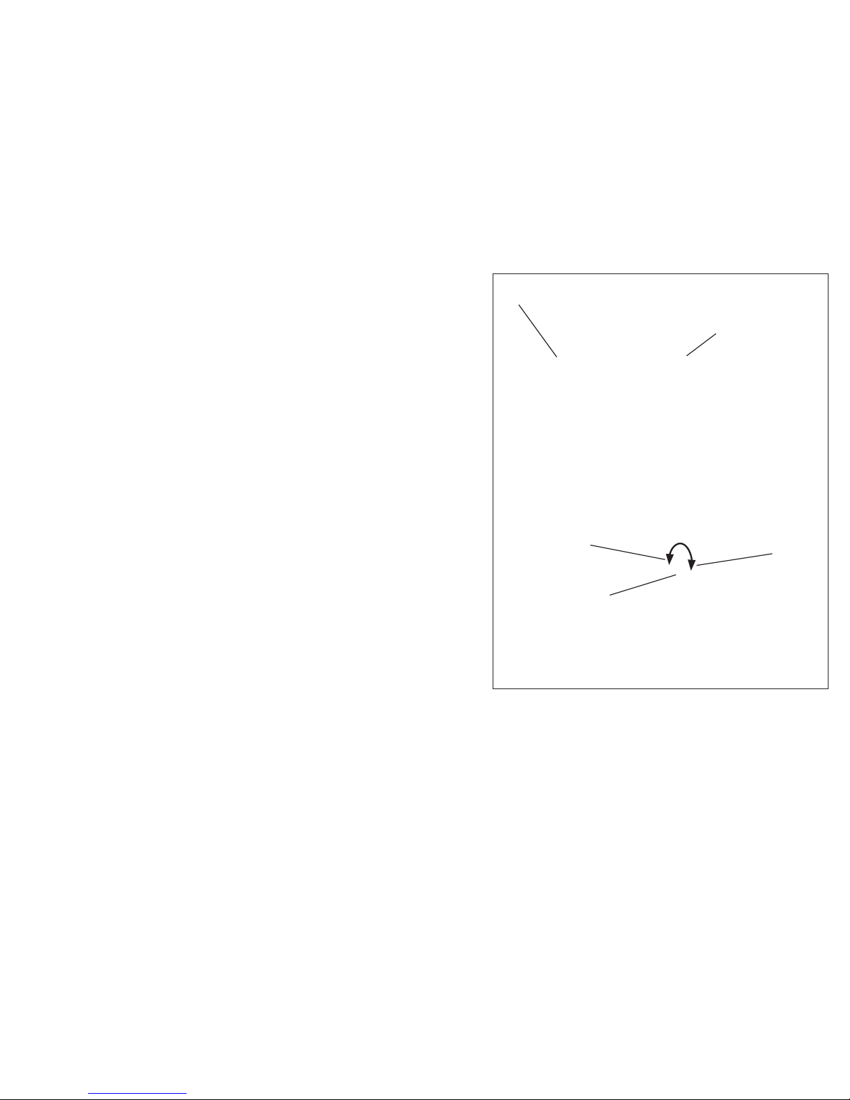
5-8. Checking and adjusting the timer
The screw transport feed differs depending on screw type. This machine can make screw unloading smooth through timer adjustment.
For screws with a low transport speed, set the timer long. For screws
with a high transport speed, set the timer short.
・
This machine continues its operation when no screw is found at the
screw extraction site. The machine continues operating with a screw at
the extraction site but will stop, after a certain lapse of time, if the screw
is not extracted. This time lapse can be varied by adjusting the timer.
After the screw is extracted, the machine starts operating again.
・
Check the operation by intercepting the optical axis of the sensor.
・
Make an adjustment with the timer knob at the rear of the machine body
(as shown in the gure on the right).
・
When the timer knob is turned clockwise, as viewed from the rear side,
the time becom es sh orter. When the knob is turned counterclockwise, the
time becomes longer.
・
Make this adjustment, by using the accompanying screwdriver, within
the allowable turning range, without using excessive force.
・
Do an operational check with screws loaded in the scooping chamber
and set the timer properly.
Adjust the timer with
the timer knob.
When the optical axis of the
sensor is intercepted, the
timer will function to stop the
operation of the machine.
Longer
Shorter
Timer knob
- 10 -
 Loading...