


Operation manual No. ET-C005
16A
Utilizing 100% post-consumer
recycled paper pulp
The Torque Value Checking Meters
For Automatic Controlled System
HM-10
HM-100
Operation Manual
(As of December 2016)
1-16-5 Akiyama, Matsudo City,
Chiba Pref., Japan
TEL: 81 (Japan) 47-392-2001
FAX: 81 (Japan) 47-392-7773

- 1 -
Thank you for purchasing the HIOS torque meter.
The HM series torque meters are carefully designed to be exclusively used for automatic controlled
systems. This series of torque meters can measure torque without removing the screwdriver mounted
on the system.
Please read the following notes carefully before use. We hope you will use our product for a long time.
■
Features
1. You can measure the screwdriver torque as it is mounted on the automatic controlled system, and
without removing the bit.
2. The detector is compact and you can easily measure the torque even in a small space.
3. The digital display helps easy and precise reading.
4. This instrument can save and indicate peak values for precise measurement.
5. You can carry around this instrument because it is rechargeable and portable.
6. You can use commercially available tools for collection as well as analysis of measurement data.
7. You can also measure the torque of a motor screwdriver for manual use.
●
You need to use HIOS’s Fidaptor and a commercially available conversion plug for measurement
of the torque of a motor screwdriver for manual use.
A conversion plug allows static (real-time) measurement. For details, please contact us.
8. Analog outputs can be used for multiple purposes including waveform observation, recording or
judgment of measurement results (an analog cord is optional).
Caution
Read the notes below carefully for safe and proper use.
Before using this instrument
●
Make sure to carefully read this operation manual and the notes attached to the instrument before
use for safe and proper use.
●
The torque meter (display unit) and the detector are calibrated and controlled with the same serial
number. Always use the proper combination referring to the serial number.
●
Please note that HIOS is not responsible for malfunctions caused by unauthorized modification,
disassembling and handling of the instrument other than those specied in the operation manual.
Cautions at work
●
When you measure a rotational device including a screwdriver, pay attention to the surroundings (e.g.,
working table) so that nothing will be involved in the rotation.
●
When you detect anything abnormal, stop operation immediately. Wear working clothes properly
before starting operation, and fully close the cus, buttons and zippers.
●
Do not wear gloves during operation because they may be slippery.
●
Since the detector is small, x it rmly for measurement to avoid it being swung around.
●
Do not throw around the detector; do not hit it, as such handling may cause the instrument to
malfunction.
●
Since the strain gauge of the detector is sensitive to the surrounding environment, be sure to set it to
[TRACK] mode at power-on and conrm zero is displayed. Please adjust it to zero occasionally while
in use. (*1)

- 2 -
Notes for use
●
Never apply the torque exceeding the maximum value displayed on the instrument. If you do so, the
instrument will break inside.
●
For correct handling of Fidaptor, refer to page 4.
●
Do not use attachments except Fidaptor and other specied attachments.
●
Do not use the instrument with a device that gives repeated shocks such as an air screwdriver or an
impact wrench. (*2)
●
When you attach Fidaptor to the socket, always x it with screws in four directions. (*3)
●
Do not loosen the screws xing the socket. (It may cause a precision error.)
●
For correct handling of the charger, refer to page 11.
●
Do not connect to the data output connector anything but the devices specied in the operation
manual.
●
When you insert or remove a connector to/from a cord, hold the connector head and check the pin
arrangement.
●
Always turn o the power after nish using the instrument.
●
Do not hit or apply a load to the display plate (acrylic plate).
●
Do not change the internal volume for calibration, etc.
●
Do not handle the detector roughly or drop it.
●
Do not use the detector in inappropriate places described below:
・
A place where water, oil and other uids may be scattered
・
A place where vibrations, dust or heat may exist
・
Outdoors and a place where electric noises may exist
・
A place with high temperatures and high humidity (preferable temperature: 15°C-35°C, preferable
humidity: 25%-65%)
・
Other places where malfunctions and functional damages may be caused
●
Do not store the instrument where the temperatures or humidity may change signicantly. If you do
so, condensation may occur inside the detector resulting in functional damage.
◎
Important
*1. Before performing zero adjustment, set the unit to the TRACK mode and check if “zero” is
displayed.
*2. If you want to measure the torque of an air screwdriver or an impact wrench, we have the HIT
series for that purpose. Please consult with us.
*3. When you attach Fidaptor to the socket, x it rmly at four points. (Refer to the external views of
the detector on pages 5 and 15.)
*4. If you turn the zero adjustment knob in the PEAK mode, the reset function will be disabled.
In that case, turn the measurement mode switch to TRACK and perform “Peak” measurement
after conrming zero is displayed. (Refer to Section 7.8 on page 6.)

- 3 -
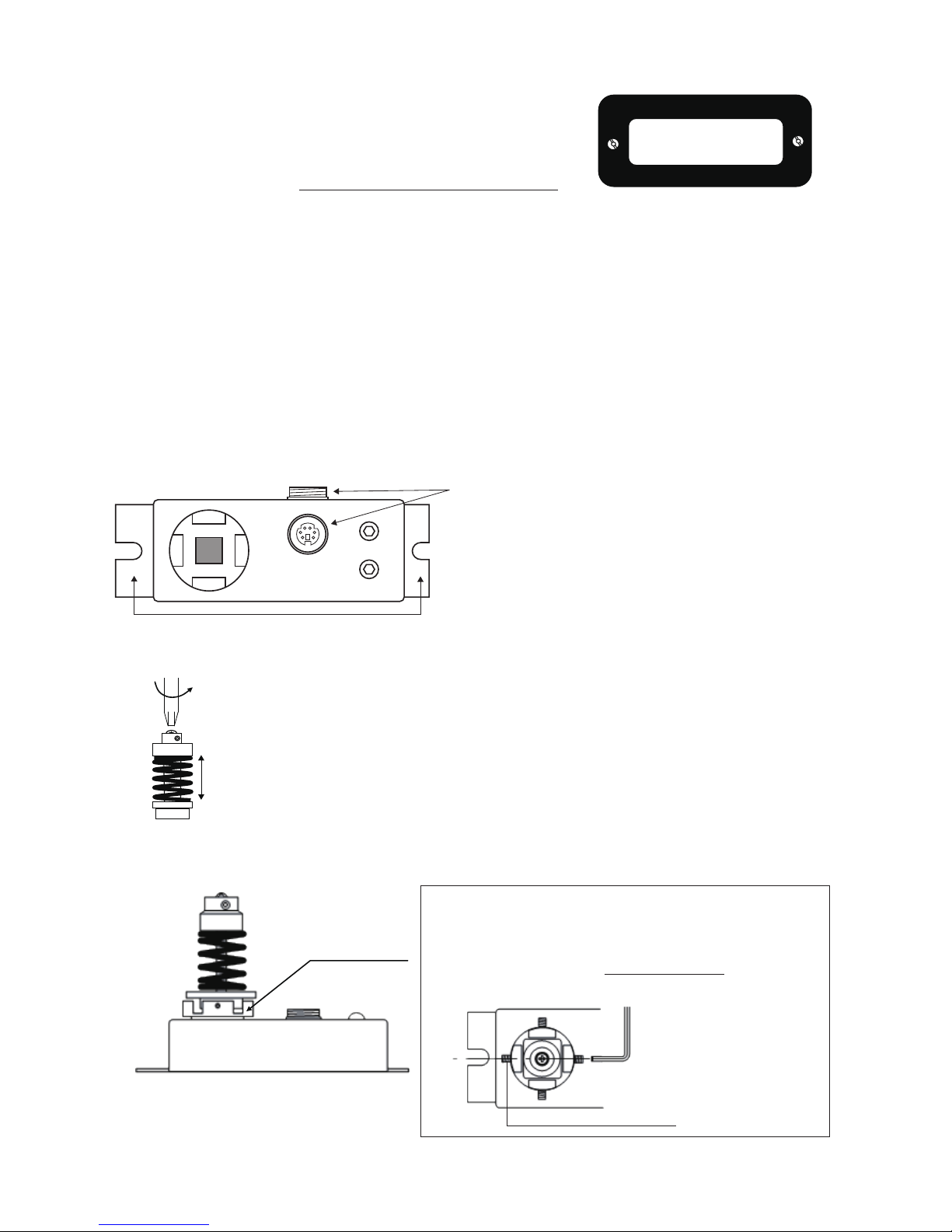
■
Parts Name
Display unit
Printer Output
connector
Display Panel
Buzzer Set
Power
Switc
h
Reset
Button
Zero Adjustment Knob
Socket
Cable
DPC-0506, 1.7m
(The same shape at
both ends)
Mode Switch
PERK←→TRACK
Connectors
・
There are two connectors.
・
One is covered with a cap for protection.
Analog Output
Connector
Connect for
Charger
Unit Converter Switch
Lbf・in←→kgf・cm←→N・m
Display unit (back)
(Serial No. sticker is attached.)
Side of the detector:
(Serial No. sticker is attached.)
DETECTOR
●
Mode Switch
TRACK: The value on the display changes as the load to the detector changes.
(The value will disappear when no load is applied.)
PEAK: The maximum value of load is captured. (The value will disappear when you press the reset
button.)
●
Buzzer Set
The buzzer will start sounding when the torque reaches the specied torque.
●
Display panel (unit):
●
Conversion of N・m: 1N・m≒10.2 kgf・cm
Model N・m N・cm N・m N・cm kgf・cm
HM-100 0.00 0 10 1000 102
HM-10 .000 0.0 1 100 10.2
9.81 981 100
0.981 98.1 10

- 4 -
■
Items included with the torque meter
●
Both the main unit and accessories are packed in a dedicated aluminum attaché case
Model Fidaptor
Fidaptor
Screw for head
replacementa
Fidaptor
spring
Charger
L-shaped
wrench
Others
1 piece each
HM-10
P/N:
TEM 26-Z
Yellow spring
1 piece
5 pieces of Phillips head
pan screws, M2.6 x 6mm
2 pieces of hollow set
screws, M3 x 6mm
-
AC100V
P/N
TCH-100N
1 piece
Opposite side
dis.:
1.5mm
1 piece
・
Cord for
detector
P/N: DPC0506
・
Inspection
report
HM-100
P/N:
TEM40-Z
Black spring
1 piece
5 pieces of Phillips head
pan screws, M4.0 x 8mm
2 pieces of hollow set
screws, M4.0 x 6mm
Measurement
range:
0.15-0.6 N・m
Yellow spring
1 piece
Opposite side
dis.
1.5mm,
2.0mm
1 piece each
●
Fidaptor list
Model
HM-10
HM-100
Standard accessory
Standard accessory
Optional accessory
(separately sold)
P/N TFM 26-Z TFM 20-Z TFM 40-Z
Measurement range
(N・m)
0.15-0.6 0.25 or smaller 0.5-3
(Yellow spring)
(Red spring)
(Black spring)
Supporting bit No. +#1 +#0 +#2
Head screw diameter
M2.6
(P/N: SPP26×060SUS)
M2.6
(P/N: SPC26×060)
M4.0
(P/N: SPP40×080SUS)
■
About Fidaptor (accessories)
Use Fidaptor for torque measurement of the screwdriver for an automatically controlled system.
For #1 bit For #2 bit
(Note)
When the screw head on the threaded shaft
wears, measurement results vary. Please
replace it as soon as possible.
HM-10
P/N TFM 26-Z
HM-100
P/N TMF 40-Z
●
Replacement of the head screw (preferably replace it within 10
operation cycles.)
Use the attached L-wrench to loosen the hollow set screws (M3)
before the head shape collapses.
Use the L-wrench to lock the rotation of the hollow
set screw and unfasten the head screw.
Suitable wrench size: 1.5mm for HM-10, 2.0mm for
HM-100. Spare screws are included.
Use L-wrench to lock the rotation
and unfasten the screw.
- 5 -
■
Operation procedure
●
How to check torque using Fidaptor
First, connect the torque meter (HM) to the detector.
Then turn on the power and conrm if the battery has been charged.
・
How to check the battery
①
Turn on the power.
②
Set the measurement mode to TRACK.
③
If the battery is low, “LOBAT” is displayed in the upper left corner of the display.
Then, charge the battery (do not charge longer than eight hours). Use the chargers for this battery.
(Note) Do not take measurements while charging the battery.
2. Fix the detector. There are two points for xing. (See the dimensional drawing of the detector on
page 15.)
3. Connect the cord to the detector.
Connect the cord to the detector. There are two connectors. Use one of them considering the
workability.
*Make sure the connector has the correct shape. If you ignore this, it may cause pin bending.
(Note)
There are two connectors.
Use one of them and cover the other one with a cap.
Points for xing
4. Use the handy screwdriver to loosen the threaded shaft ring of Fidaptor a little.
A spring
Loosen the shaft so that you can turn the spring with your ngers.
The shaft should always go back to the same position.
5. Set Fidaptor to the socket.
5-1 Fix Fidaptor to the socket.
LOBAT
When “LOBAT” is displayed, start
charging the battery.
●
Important
In order to fix Fidaptor, use the L-shaped wrench
(1.5mm) to fasten four hollow set screws (M3.0) on
the side of the socket with even torque.
This way you can measure in a stable manner.
Hollow set screw (M3, 4 pieces)
L-shaped wrench, 1.5mm

- 6 -
5-2. Set the bit end of the target screwdriver to the center of the head screw of Fidaptor.
◎
Important
Notes when xing Fidaptor:
(1) In order to have the bit set right in the center of the head screw of
Fidaptor, you need to x Fidaptor by fastening the four screws on the
side evenly.
(2) The bit tip should be engaged precisely in the head screw of Fidaptor
for measurement (it should be correctly aligned with the thrust
direction and the center of the screw.)
(3) Especially, when you use it in the automatically controlled system, it
should be aligned with the center of the Z-axis.
6. Set the switch for measurement unit change to your desired unit.
MODE
TRAK
PEAK
RESET
OFF
O N
POWER
MADE I N JAPAN
N m
lbf in
kgfcm
・
・
・
HM
Unit converter
Switch
7. Set the mode switch to TRACK and turn the zero adjustment knob for zero adjustment.
MODE
TRAK
PEAK
RESET
OFF
O N
POWER
MADE I N JAPAN
N m
lbf in
kgfcm
・
・
・
HM
Turn the knob for zero adjustment.
(Note) Zero adjustment is not available with the PEAK position.
Check if “000” is displayed.
Set the mode switch to TRACK.
8. Set the mode switch to PEAK.
MODE
TRAK
PEAK
RESET
OFF
O N
POWER
MADE I N JAPAN
N m
lbf in
kgfcm
・
・
・
HM
Set the mode switch to PEAK.
After measurement, clear the value with the RESET button.

- 7 -
9. Turn the screwdriver for measurement.
When the clutch is disconnected, the spring is compressed.
The measurement is displayed in the window and saved.
This is the output torque of the screwdriver.
21.3
When the clutch of the screwdriver
is disconnected, the measured
value is displayed in the window
and saved.
10. Let Fidaptor recover from contraction to return to the constant height.
*Use the handy screwdriver to loosen the threaded shaft.
(Note) Always let the spring recover the constant height by loosening.
◎
Important
The target looseness is that “the
spring can be turned with the fingers”
to always have a constant height.
11. Cancel the value in the window by pushing the Reset button.
MODE
TRAK
PEAK
RESET
OFF
O N
POWER
MADE I N JAPAN
RESET button for cancelling the value
*Note for resetting
(1) Let Fidaptor return to the constant height before
pushing the RESET button for cancelling the value.
(2) Let the socket section have no load.
(Note) It cannot be reset if there is a load.
N m
lbf in
kgfcm
・
・
・
HM
12. Repeat the steps 10 to 12 to determine average output torque.
Furthermore, if you want to set any torque, adjust the screwdriver’s nut for torque adjustment and
follow the same procedure.
13. When you nish measurements, always loosen Fidaptor.
At the end of the operation for the day, turn o the power and remove everything from the socket.
(Note) Make sure to loosen the Fidaptor spring at the end of operation and store it.

- 8 -
14. For aggregation of measurement data, turn the mode switch to PEAK.
For measurement, an input signal (torque = load) of 15 digits or larger is required. If you press the
Reset button, the data will be output and the value in the display window will be cancelled. (For the
data output tool, refer to the description on page 16.)
●
About “digit”
“digit” means the unit of a value to be displayed regardless of the decimal point.
(Examples) .0.01 = 1 digit
.025 = 25 digits
.10 = 10 digits
1.25 = 125 digits

- 9 -
■
How to set the buzzer
Zero adjustment knob
Buzzer set knob
(Notes)
●
Check if the display unit is connected to the detector.
●
The buzzer is set to 0.981 N・m (HM-10) and 9.81 N・m
(HM-100) by default when shipped.
<Setting procedure>
Turn on power
Set to TRACK mode
・
Turn the knob to set the
value at which you want
to start the buzzer.
・
Use the zero adjustment knob to
set zero on the display.
・
Check the value after the buzzer.
・
The buzzer starts sounding
when the displayed value reaches
the set value.
・
Stop turning the knob when you
hear the buzzer.
Use the zero adjustment
knob to set the value
Turn the buzzer
adjustment knob
Confirm the value
Set zero on display
Measure in PEAK mode
●
Measurement after setting the buzzer
(1) Apply load to the detector.
(2) When the load reaches the preset value, the buzzer starts; and:
In the case of the TRACK mode: The buzzer stops when you release the load; “zero” is displayed.
In the case of the PEAK mode: The buzzer and the display continue even when you release the
load.
You can stop the buzzer and the display by pressing the Reset button.
●
When you don’t use the buzzer setting, turn the buzzer set knob to specify the value more than the
working value (same as the default).
■
How to replace the spring (attached to HM-100)
HM-100 has two springs: black (strong) and yellow (weak).
A black spring is attached to the Fidaptor.
If you measure a smaller range of torque, replace the black spring with the yellow
one.
(Note) Set the bit of the screwdriver to the Fidaptor’s head screw and turn it
counterclockwise.
Then the threaded shaft becomes loose to enable replacing the spring.
Replace

- 10 -
■
Inspection of Fidaptor
●
Handling of Fidaptor
1. Never apply a load more than the measurement capability specied for Fidaptor.
2. Use Fidaptor appropriate for the screwdriver and the torque.
3. Always keep Fidaptor loose and remove everything from the socket after measurement.
4. Try to keep the screwdriver and Fidaptor upright while measuring and apply the thrust load of 5kg
or smaller.
(In the case of a lower range of torque, the thrust load should be 2kg or smaller.)
5. For continuous measuring, apply grease to the component parts of Fidaptor.
6. Set the measurement cycle to 5 seconds or longer. If you set the cycle to a time dierent to that,
the component parts will wear quickly.
7. Never leave or store Fidaptor in a fastened state.
When you don’t use Fidaptor, loosen the spring.
8. Correctly engage the object for measurement and Fidaptor.
9. Don’t use a deformed or modied Fidaptor.
●
Maintenance and inspection of Fidaptor
1. Apply grease (*) to the components (1), (2) and (5) (see the gure below) of Fidaptor regularly.
2. Check the components below before you use Fidaptor:
1) The components (1), (2) and (5) have been greased.
2) The threaded shaft is not bent and the threads have not worn.
3) The threaded shaft is free from foreign materials.
3. Fidaptor is a consumable component. Inspect it regularly and replace it whenever required.
(1) Threaded shaft
(2) Bearing set
(3) Bearing housing
(4) Spring
(5) Plate nut
[Replacement guide] See the gure to the left for the
components (1)-(5).
Components (1) and (2): every 2,500 cycles (1 stroke =
1 cycle)
Component (1): when the shaft is bent or the threads
have worn.
Component (4): it should be replaced together with the
component (1).
Component (5): every 5,000 cycles
Note: The grease is available from HIOS. (Separately sold,
grease P/N: TF-3G)

- 11 -
■
How to use the socket
This instrument can measure various kinds of torque other than that of screwdrivers by changing
the attachment.
●
When you use a customized attachment, you must pay attention to the matters below.
Matters requiring attention when you use a customized attachment:
・
There must be no play between the socket and the attachment.
・
The attachment must have sucient strength to prevent breakage during measurement.
・
The vertical load to the socket must be 2kg or smaller for HM-10 and 5kg or smaller for HM-100.
・
There must be no impact load to the socket.
・
There must be no violation to the principles of the torque measuring instrument.
For details of the socket, please refer to the outline view on page 15.
■
Battery charge
Always use the dedicated charger and make sure to turn off the power of the main unit before
starting charging.
When you charge the battery for the rst time, it will take eight hours to charge it fully.
Caution
Please read the following carefully.
●
Do not charge the battery longer than eight hours.
●
Use only NiMH batteries, never any other kind, even if obtained from HIOS Corporation.
●
Do not use the instrument while charging the battery.
●
When “LOBAT” is displayed in the window, stop measurement and charge the battery.
●
Do not use the dedicated charger for other purposes.
●
Do not place anything heavy on the cord of the charger, and do not bend or bind it.
●
Always turn o the power when you connect or disconnect the battery.
●
Do not remove the battery in the main unit.
Danger
If you charge the battery for more than eight hours, it may
cause heating, explosion, deterioration, a re, etc.
■
How to charge the battery
1. Turn o the power switch of the instrument and connect the charger’s plug to the connector.
2. When charging starts, the red LED of the charger will turn on.
(Note) The LED indicates the charger is correctly connected to the instrument and charging the
battery is in progress. However, please note that the LED will stay on after fully charged.
3. When charging is completed, disconnect the plug and turn on the power switch of the instrument
to check the display.

- 12 -
■
Customer service
●
Repair
1. Service charges will be made for repairs under the following circumstances:
(1) Malfunctioning or damage caused by incorrect use of the instrument, the instrument has
been disassembled or it malfunctions due to attempted repair.
(2) Oil has been added to the socket, switches or inside the instrument.
(3) The instrument has been damaged during shipping, by dropping, etc.
(4) Damage due to re, exposure to gas, earthquake, water, irregular power supply or other type
of disaster.
(5) Service charges will also be made for calibration, inspection or parts replacement for the
Fidaptor, etc.
2. No charge will be made for service in the case of inspection and/ or calibration of the same
part that becomes necessary within three months after inspection or calibration has been
performed. (This does not apply under circumstances (1) − (4) above.)
●
Shipping and handling charges incurred for repair service must be paid by the customer. Please
direct questions about customer services to HIOS Corporation or your HIOS dealer.
■
Attention
The product that you have purchased contains a rechargeable battery. The battery is recyclable. At
the end of it’s useful life, under various state and local laws, it may be illegal to dispose of this battery
into the municipal waste stream.
Check with your local solid waste officials for details in your area for recycling options or proper
disposal.

- 13 -
■
Troubleshooting (before deciding the instrument has failed)
Before deciding the instrument has failed, refer to the table below for troubleshooting. If this does
not solve the problem, please contact your dealer or HIOS.
Symptom Possible cause Action to take
“LOBAT” in the display
・
Insucient charging of the
battery
・
Charge the battery. Refer to P. 11.
・
If nothing is displayed even
after charging the battery, please
contact us.
Nothing appears on the display
・
The instrument has not been
used for a long time, or the battery
has died.
・
Turn o the power and charge
the battery for about 10 minutes
and turn on the power. If the
display becomes active, then
charge the battery within eight
hours for ordinary use.
・
If it doesn’t solve the problem,
please contact us.
Cannot set it to zero
・
Reset does not work if the display
value without a load exceeds 10
digits.
・
Set the Mode switch to TRACK
and see if zero will be displayed.
(Perform this zero adjustment
in the TRACK mode occasionally
while in operation.)
The value cannot be held.
・
The Mode switch is set to TRACK.・Set it to PEAK.
・
Zero adjustment has not been
done.
・
The connection cable is wrongly
connected or it is broken.
・
Use the zero adjustment knob
for adjustment.
・
Replace the cable.
The instrument cannot be charged
・
The plug of the charger is not
inserted correctly.
・
Check if the plug is correctly
inserted.
・
The plug is connected to the
wrong terminal.
・
Connect it to the right
connector.
・
If it doesn’t solve the problem,
please contact us.
The LED of the charger doesn’t
turn on.
・
The cord of the charger is broken.
・
Check if the plug is connected to
the right terminal.
・
The plug of the charger is
connected to the wrong terminal.
・
If it doesn’t solve the problem,
please contact us.
After charging the battery it still
displays insucient charging.
・
The battery died.
・
Repair is required.
・
Still insucient charging of the
battery
・
Charge the battery again not
exceeding eight hours.
An irrelevant value is displayed
・
Noises cause wrong value
display.
(When power is on or in the PEAK
mode)
・
Press the Reset button to delete
the value.

- 14 -
■
Specications
Model HM-10 HM-100
Peak measuring range
N・m 0.015-1.000 0.15-10.00
lbf・in 0.15 - 9.00 1.5 - 90.0
N・cm 1.5-100.0 15-1000
Accuracy Within ±0.5% (F.S.)
Battery pack 6V NiMH
Charging time 8 hours or less
Weight (kg) Display unit 1.0kg
Detector 0.35kg
Continuous operating time on a full charge
30 hours
Battery life 300 cycles of charging
Detector cord 1.7m (6P cord), P/N: DPC-0506
Exclusive battery charger Input: AC100V, 120V, 220-240V
Output: DC7.2V 120mA
(P/N: TCH-100N)
●
Never apply the load more than the maximum allowable load.
●
We cannot guarantee the life of the battery in the specication table because it varies depending
on the usage pattern.
●
Instruments for use in foreign countries are also available (input: AC120V, 220-240V).

- 15 -
■
Outline dimensional drawing (and detailed socket dimensions)
2.3
26
35
30
Note: The dimensions of the detector in this drawing are not full-scale.
unit:mm
“Detector”
“Main unit”

- 16 -
■
Specications for analog output
It is about 12V at the maximum torque.
(Maximum torque: 9.81N・m for HM-100; 0.981N・m for HM-10)
●
If you want to use it as an output unit for observed waveforms, you may need the devices below:
Oscilloscope, voltage meter, analog data collection system (Keyence), data logger (Hioki), etc.
Also prepare a dedicated cord for analog data output (P/N: HP-8060, 1.5m).
*Use the devices properly after reading the operation manuals attached to the devices.
■
Data output
If you want to transfer the data to your PC, please use the input tool of Mitutoyo.
A connection cable (separately sold) is also required to connect the input tool and the torque meter.
●
Types of input tools
・
USB keyboard conversion type, P/N: IT-012U 264-012
・
Keyboard signal conversion type, P/N: IT-005D 264-005 (for DOS/V)
●
Connection cable: IT937244, 5 pins, 2m
* For the input tool and the printer connection cable, contact Mitutoyo or your dealer.
Regarding import of measurement data, please contact HIOS.

- 17 -
■
Specications for serial output
1. Connector pin arrangement: Mitutoyo MQ65-5P
①
GND: Ground
②
DATA: The data is output in the format below
③
CK: Clock
④
RD: Request for data
⑤
REQ: Request of data output from the outside
①
to ④: Open drain; -0.3 to +7V (400μA max.)
⑤
: it is pulled up to VDD (1.55V).
2. Data output format
13 digits are output in the sequence below:
d
1 d2 d3 d4 d5 d6 d7 d8 d9 d10 d11 d12 d13
Sign
Entry number
Data type
Decimal point position
Measured value
Each digit is expressed with a 4-bit binary and output from LSB in the sequence: 2
0
→
2
1
→
2
2
→
2
3
.
3. Timing chart
MIN MAX UNIT
T
0
2 - sec
T
1
0.2 0.4 sec
T
2
0.2 0.4 mS
T
3
0.5 1 mS
T
4
0.2 0.4 mS

- 18 -
■
The following table is for CHINA RoHS2
If you are asked by China Customs, please show this table to them.
有害物质名称及含量标识格式
产品中有害物质的名称及含量
部件名称 有害物質
铅(pb) 汞 (Hg) 镉 (Cd) 六价铬
(CR(VI))
多溴联苯
(PBB)
多溴二苯醚
(PBDE)
充电池 ○ ○ ○ ○ ○ ○
外壳 ○ ○ ○ ○ ○
电源适配器 × ○ ○ ○ ○ ○
本表格依据 SJ/T 11364 的规定编制。
○:表示该有害物质在该部件所有均质材料中的含量均在 GB/T 26572 规定的限量要求以下。
×:表示该有害物质至少在该部件的某一均质材料中的含量超出 GB/T 26572 规定的限量要求。
In addition, the China RoHS marks also is required at the product and product box.
At the product, you can nd it at the bottom and it is marked on the product box.
If you cannot nd the mark, please ask your distributor.
In case of emergency, please cut the mark below and stick at the bottom of product and on the product
box.
ChinaRoHSmark

 Loading...