


Current-Controlled Screwdriver
DCD-40L (115W)
Instruction Manual
ET-A070 19A
HIOS Inc.

■ Introduction
This manual describes the touch panel operations and functions of the screwdriver.
■ Abbreviations and terminology
The abbreviations and terminology used in this manual are defined in the table below.
Abbreviation/terminology Definition
SVC or controller SV-NET Controller
SVD or driver SV-NET compatible driver
Servo motor or motor AC servo motor
2 / 52

Contents
■ Introduction .......................................................................................................................................................................... 2
■ Abbreviations and terminology ............................................................................................................................................ 2
Contents ................................................................................................................................................................................... 3
1. Startup screen....................................................................................................................................................................... 5
2. Main screen .......................................................................................................................................................................... 6
3. [Program Preview] screen ..................................................................................................................................................... 7
3.1 Screen display items ....................................................................................................................................................... 7
■ Screen display items (buttons) ..................................................................................................................................... 7
■ Screen display items (numeric values) ......................................................................................................................... 8
4. [Operate] screen ................................................................................................................................................................... 9
4.1 Screen display items ....................................................................................................................................................... 9
■ Screen display items (buttons) ..................................................................................................................................... 9
■ Screen display items (numeric values, lamps) ........................................................................................................... 10
5. [Monitor Operate] screen .................................................................................................................................................... 11
5.1 Screen display items ..................................................................................................................................................... 11
■ Screen display items (buttons) ................................................................................................................................... 11
■ Screen display items (numeric values) ....................................................................................................................... 12
■ Screen display items (lamps) ..................................................................................................................................... 12
6. [Edit] screen ........................................................................................................................................................................ 13
6.1 Password input .............................................................................................................................................................. 13
■ Screen display items (numeric input) ......................................................................................................................... 14
■ Screen display items (buttons) ................................................................................................................................... 15
7. [HIOS] setting screen .......................................................................................................................................................... 16
7.1 Password input .............................................................................................................................................................. 17
■ Screen display items (numeric input) ......................................................................................................................... 18
8. Operation parameters ......................................................................................................................................................... 20
■ Parameter settings for each operation pattern ............................................................................................................... 20
■ Parameter setting range for operation patterns.............................................................................................................. 21
■ Parameter setting range for special settings .................................................................................................................. 23
9. Operation pattern timing charts ........................................................................................................................................... 26
■ Pattern 1 ........................................................................................................................................................................ 26
■ Pattern 2 ........................................................................................................................................................................ 27
■ Pattern 3 ........................................................................................................................................................................ 28
■ Pattern 4 ........................................................................................................................................................................ 29
10. Manual/auto mode ............................................................................................................................................................ 30
■ Manual mode ................................................................................................................................................................. 30
■ Auto mode...................................................................................................................................................................... 31
11. I/O ..................................................................................................................................................................................... 31
11.1 I/O allocation table ....................................................................................................................................................... 31
3 / 52

■ I/O input signals .......................................................................................................................................................... 31
■ I/O output signals ....................................................................................................................................................... 32
11.2 I/O input signal reception time table ............................................................................................................................ 32
■ I/O input signals .......................................................................................................................................................... 32
11.3 I/O input signal sequence ............................................................................................................................................ 34
■ Sequence of each input control signal ........................................................................................................................ 34
■ Output status signals .................................................................................................................................................. 35
11.4 I/O input timing charts .................................................................................................................................................. 36
■ Timing chart for normal operations when torque judgment is OK ............................................................................... 36
■ Timing chart for normal operations when torque judgment is NG ............................................................................... 37
■ Timing chart when emergency stop signal is input ..................................................................................................... 38
12. Message window .............................................................................................................................................................. 39
■ Displayed messages ...................................................................................................................................................... 39
■ Message list ................................................................................................................................................................... 43
13. System settings................................................................................................................................................................. 44
■ Displaying the system settings screen ........................................................................................................................... 44
■ Checking the screw tightening OK judgment count ........................................................................................................ 44
■ Checking the total number of screw tightening OK judgments ....................................................................................... 44
■ You can check the total number of times that the screw tightening OK judgment has been counted. ........................... 44
14. Button touch operations .................................................................................................................................................... 45
15. Holding time ...................................................................................................................................................................... 46
■ Holding time setting ....................................................................................................................................................... 46
16. Detailed pattern diagrams ................................................................................................................................................. 47
■ Chattering judgment ....................................................................................................................................................... 47
17. Alarms ............................................................................................................................................................................... 49
17.1 Error list (motor driver errors) ...................................................................................................................................... 49
17.3 Error list (SVC errors) .................................................................................................................................................. 52
4 / 52
■ Startup screen
1. Startup screen
The title screen is displayed when the touch panel first starts up.
After a few moments, the main window is displayed.
Fig.1-1 Title screen
5 / 52

■ Main screen
2. Main screen
On the main screen, select the screen that you want to display.
Touch a button to display the corresponding screen.
If the external I/O is set to auto operation mode input, operation starts when the external I/O start signal is ON, even while the
main window is displayed.
* If the external I/O channel No. and pattern No. are not selected, an operation error (103) occurs.
The [Program Preview] screen and [Edit] screen cannot be opened in auto operation mode.
Fig.2-1 Main screen
6 / 52
■ [Operate] screen
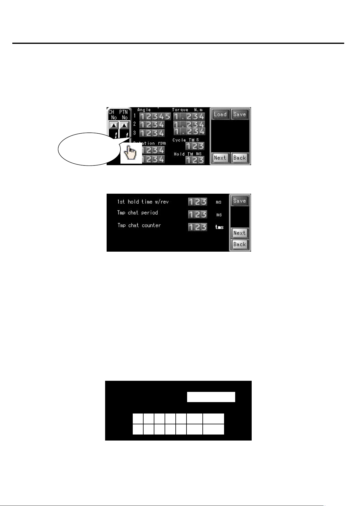
3. [Program Preview] screen
On the [Program Preview] screen, you can select the tightening operation pattern, load the saved parameters, and check the
parameters.
Fig.3-1 [Program Preview] screen (1/2)
3.1 Screen display items
■ Screen display items (buttons)
Screen display
button
Fig.3-2 [Program Preview] screen (2/2)
Description
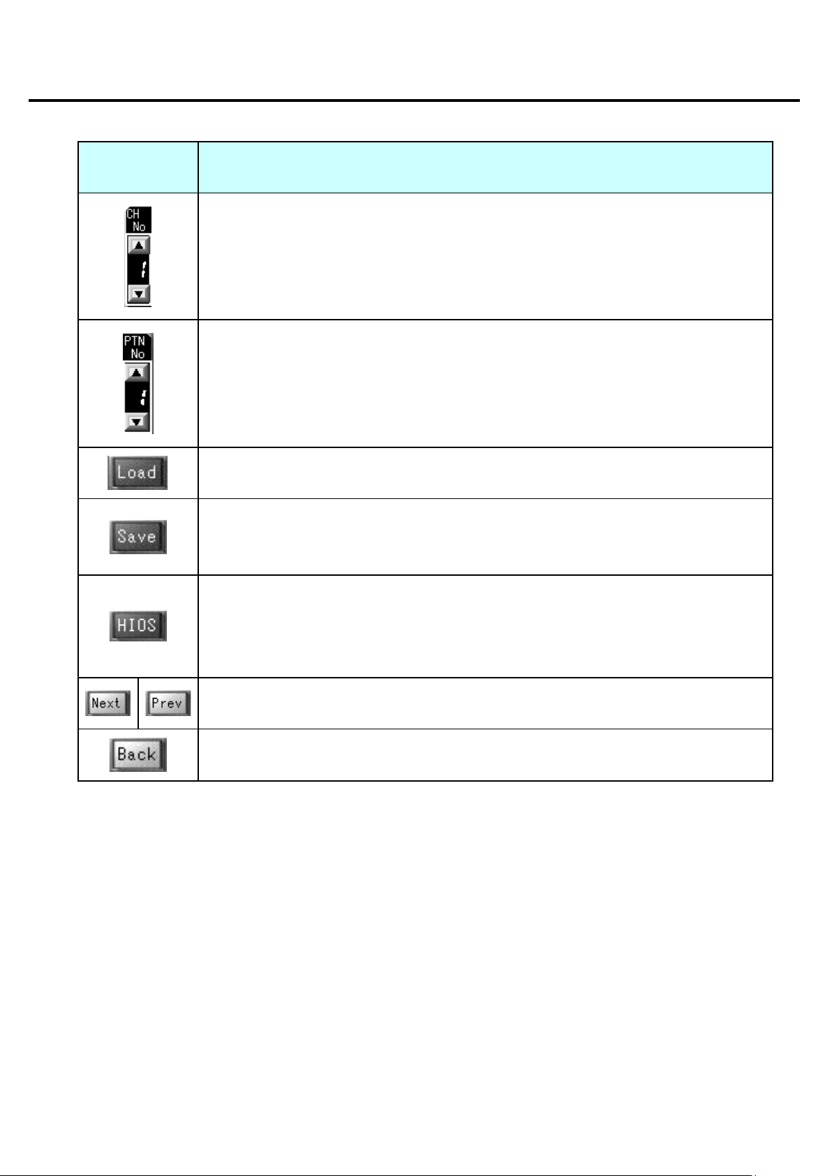
Select the channel No. Touch the [▲] button to increase the number, and touch the [▼] to decrease
it.
A value from 1 to 8 can be selected.
Select the pattern No. Touch the [▲] button to increase the number, and touch the [▼] to decrease
it.
A value from 1 to 4 can be selected.
Load the saved parameters for the combination of channel No. and pattern No.
When loading is complete, the [Data loaded] message window is displayed.
Display the next or previous page to check the parameters.
Return to the main screen.
7 / 52

■ [Operate] screen
Setting range value for when motor torque value judgment is performed in screw tightening judgment.
Example: When the torque judgment range is ±10% for a torque setting of 1 N.m, the judgment is OK
Setting for number of times that normal motor torque value is detected, for screw tightening judgment.
The judgment is NG if the number of times that the normal motor torque value is detected is outside
■ Screen display items (numeric values)
Numeric value
display item
Angle 1
(Rotation angle 1)
Angle 2
(Rotation angle 2)
Angle 3
(Rotation angle 3)
Rotation 1
(Rotation speed 1)
Rotation 2
(Rotation speed 2)
Trq 1
(Torque 1)
Trq 2
(Torque 2)
Description
Rotation angle setting for temporary tightening. The unit is ° (degrees).
Rotation angle setting for loosening. The unit is ° (degrees).
Rotation angle setting for additional tightening. The unit is ° (degrees).
Rotation speed setting for temporary tightening. The unit is rpm.
Rotation speed setting for full tightening, loosening, and additional tightening. The unit is rpm.
Torque setting that is applied when switching from temporary tightening to full tightening. The unit is
N.m.
Limit torque setting for full tightening. The unit is N.m.
Trq 3
(Torque 3)
Cycle TM
(Cycle time)
Hold TM
(Holding time)
Torque allowance
(Torque judgment
range)
Counter (Torque
judgment counter)
Limit torque setting for tightening. The unit is N.m.
Time setting for the full set of screw tightening operations. The unit is sec.
An error is displayed if the specified time is exceeded.
Holding time setting for screw tightening judgment. The unit is ms. * See Chapter 15 "Holding time".
The unit is ±%.
if the torque is from 0.9 N.m to 1.1 N.m. * See Chapter 16.
The judgment is OK if the number of times that the normal motor torque value is detected is within the
range.
the range. * See Chapter 16.
8 / 52
■ [Operate] screen
4. [Operate] screen
On the [Operate] screen, start the screw tightening operations using the parameters that have been set.
4.1 Screen display items
■ Screen display items (buttons)
Fig.4-1 [Operate] screen
Screen display button
Description
Start the screw tightening operation for the specified channel No. and pattern
No.
Stop the screw tightening operation while it is being performed. - In manual mode
[CW] (Clockwise)/[CCW] (Counterclockwise)
Select the rotation direction for screw tightening.
This setting cannot be changed while screw tightening operation is being
performed.
When an error occurs, the [Error No.] and [Error Reset] buttons are
displayed.
After removing the cause of the error, touch the [Error Reset] button to clear
When button is
enabled
- In manual mode
- Before starting
operation
- When alarm
reset IN (IN 12) is
OFF
- In manual mode
- Before starting
operation
- Always enabled
the error display.
Return to the main screen. - Always enabled
[Rev] (Reverse)
The screwdriver rotates in the screw loosening direction while this button is
touched.
9 / 52
- In manual mode
- Before starting
operation

■ [Operate] screen
■ Screen display items (numeric values, lamps)
Screen display item Description
The currently selected channel No. and pattern No. are displayed.
The start and finish status of the screw tightening operation is indicated.
[Strt] (Start): Lights up while screw tightening operation is being performed.
[Fin] (Finish): Lights up for 100 ms after screw tightening operation is complete.
The status of the screw tightening operation is indicated.
[Tmp] (Temporary tightening): The screw is being temporarily tightened.
[Full] (Full tightening): The temporary tightening operation has finished, and the
screw is being fully tightened.
[Add] (Additional tightening): The full tightening operation has finished, and the
screw is being additionally tightened.
The direction of the screw tightening operation is indicated.
[CW] (Clockwise): Screw tightening direction
[CCW] (Counterclockwise): Screw loosening direction
The current mode is indicated.
[Manl] (Manual): Manual mode
[Auto] (Auto): Auto mode
When an error occurs, the [Error No.] and [Error Reset] buttons are displayed.
The error No. of the current error is displayed.
The status of the screw tightening operation is indicated.
[START OUT]: Lights up while screw tightening operation is being performed.
[FINISH OUT]: Lights up for 100 ms after screw tightening operation is complete.
10 / 52
IN (IN 12) is OFF
manual mode.
clockwise]
[Rev] (Reverse)
■ [Monitor Operate] screen
5. [Monitor Operate] screen
On the [Monitor Operate] screen, start the screw tightening operations using the parameters that have been set.
Various information about the motor can be checked.
5.1 Screen display items
■ Screen display items (buttons)
Screen display button Description
Fig.5-1 [Monitor Operate] screen
Start the screw tightening operation for the specified channel No. and
pattern No.
When button is
enabled
- In manual mode
- Before starting
operation
- When alarm reset
[Manual]
[Clockwise]
[Auto]
[Counter-
Stop the motor while operation is being performed. - In manual mode
Switch between manual mode and auto mode.
The mode cannot be changed when auto ON is input from the external
I/O.
* These buttons can be used to switch the mode only while the [Monitor
Operate] screen is open.
When you return to the main screen, the mode automatically switches to
Select the rotation direction for screw tightening.
These buttons are enabled only in manual mode.
The direction cannot be changed while the screw tightening operation is
being performed.
Clear the current error from the error display. - Always enabled
Return to the main screen. - Always enabled
The screwdriver rotates in the screw loosening direction while this button
is touched.
- Before starting
operation
- In manual mode
- Before starting
operation
- In manual mode
- Before starting
operation
11 / 52

■ [Monitor Operate] screen
■ Screen display items (numeric values)
Screen display
item
Rotation
(Rotation speed)
Motor trq
(Motor torque)
Angle
(Rotation angle)
Hold time
(Holding time)
Error No. The error No. of the current error is displayed. For details, see the "Error list" sections.
■ Screen display items (lamps)
Description
The currently selected channel No. and pattern No. are displayed.
The motor rotation speed is displayed in units of rpm.
The motor torque is displayed in units of N.m.
The current rotation angle is displayed in units of ° (degrees).
The holding time for the screw tightening operation is displayed in units of ms.
* See Chapter 15 "Holding time".
Screen display item Description
The start and finish status of the screw tightening operation is indicated.
[Strt] (Start): Lights up while screw tightening operation is being performed.
[Fin] (Finish): Lights up for 100 ms after screw tightening operation is complete.
The status of the screw tightening operation is indicated.
[Tmp] (Temporary tightening): Temporary tightening is being performed on the
screw.
[Full] (Full tightening): The temporary tightening operation has finished, and full
tightening is being performed.
[Add] (Additional tightening): The full tightening operation has finished, and
additional tightening is being performed.
The direction of the screw tightening operation is indicated.
[CW] (Clockwise): Screw tightening direction
[CCW] (Counterclockwise): Screw loosening direction
The status of the screw tightening operation is indicated.
[START OUT]: Lights up while screw tightening operation is being performed.
[FINISH OUT]: Lights up for 100 ms after screw tightening operation is complete.
12 / 52
1 2 3 4 5
BS
ENT
6 7 8 9 0
CLR
ESC
Level 1 or above
■ [Edit] screen
6. [Edit] screen
Configure the various parameter settings that are necessary for the screw tightening operations.
Configured settings can be saved or loaded for each channel No. and pattern No.
Touch a numeric value input field to enter a value using the numeric keys. For details about each numeric value input field
and each button, see the screen display item descriptions below.
Use numeric
keys to enter
Fig.6-1 [Edit] setting screen (1/2)
Fig.6-2 [Edit] setting screen (2/2)
6.1 Password input
A password must be entered in order to display the [Edit] screen.
Touch the numeric keys displayed on the screen to enter the password. (The factory default setting is a four-digit password
{8104}, and a password of up to eight digits can be set.)
Touch the [BS] button to delete the last digit.
Touch the [CLR] button to delete all digits.
Touch the [ENT] button to log in with the password.
When the correct password is entered, the [Edit] screen is displayed. If the password is not correct, a warning message is
displayed. If no password is entered for one minute, the main screen is automatically displayed again.
Please Enter Password
6.3 Password input screen
13 / 52

The judgment is OK if the number of times that the normal motor torque value is detected is within the
judgment is NG if the number of times that the normal motor torque value is detected is outside
■ [Edit] screen
6.2 Screen display items
■ Screen display items (numeric input)
Numeric input item Description
Angle 1
(Rotation angle 1)
Angle 2
(Rotation angle 2)
Angle 3
(Rotation angle 3)
Rotation 1
(Rotation speed 1)
Rotation 2
(Rotation speed 2)
Torque 1
(Torque 1)
Torque 2
(Torque 2)
Torque 3
(Torque 3)
Rotation angle setting for temporary tightening. The unit is ° (degrees).
Rotation angle setting for loosening. The unit is ° (degrees).
Rotation angle setting for additional tightening. The unit is ° (degrees).
Rotation speed setting for temporary tightening. The unit is rpm.
Rotation speed setting for full tightening, loosening, and additional tightening. The unit is rpm.
Torque setting that is applied when switching from temporary tightening to full tightening. The unit is
N.m.
Limit torque setting for full tightening. The unit is N.m.
Limit torque setting for tightening. The unit is N.m.
Cycle TM
(Cycle time)
Hold TM
(Holding time)
Torque allowance
(Torque judgment
range)
Counter
(Torque judgment
counter)
Time setting for the full set of screw tightening operations. The unit is sec.
An error is displayed if the specified time is exceeded.
Holding time setting for screw tightening judgment. The unit is ms. * See Chapter 15 "Holding time".
Setting range value for when motor torque value judgment is performed in screw tightening
judgment. The unit is ±%.
Example: When the torque judgment range is ±10% for a torque setting of 1 N.m, the judgment is
OK if the torque is from 0.9 N.m to 1.1 N.m. * See Chapter 16.
Setting for number of times that normal motor torque value is detected, for screw tightening judgment.
range.
The
the range. * See Chapter 16.
14 / 52
configuring special settings that apply to all operation patterns, and settings that
■ [Edit] screen
■ Screen display items (buttons)
Screen display
button
Description
Select the channel No. Touch the [▲] button to increase the number, and touch the [▼] button to
decrease it.
A value from 1 to 8 can be selected.
Select the pattern No. Touch the [▲] button to increase the number, and touch the [▼] button to
decrease it.
A value from 1 to 4 can be selected.
Load the saved parameters for the combination of channel No. and pattern No.
When loading is complete, the [Data loaded] message window is displayed.
Save the currently configured parameters for the combination of channel No. and pattern No.
If parameters have already been saved for the combination, the data is overwritten.
When saving is complete, the [Data saved] message window is displayed.
Open the screen for
are specific to the motor.
Since the settings are normally configured by HIOS, a password is required in order to display the
screen.
[Next]/[Prev]
Display the next or previous page of the [Edit] screen.
Return to the main screen.
15 / 52
to enter values
■ Operation parameters
7. [HIOS] setting screen
Open the screen for configuring special settings that apply to all operation patterns and to settings that are specific to the
motor.
Since the settings are normally configured by HIOS, a password is required in order to display the screen.
Touch a numeric value input field to enter a value using the numeric keys. For details about each numeric value input field
and each button, see the screen display item descriptions below.
Fig.7-1 [HIOS] setting screen (1/6)
Use numeric keys
Fig.7-2 [HIOS] setting screen (2/6)
Fig.7-3 [HIOS] setting screen (3/6)
Fig.7-4 [HIOS] setting screen (4/6)
16 / 52

■ Operation parameters
Fig.7-5 [HIOS] setting screen (5/6)
Fig.7-6 [HIOS] setting screen (6/6)
7.1 Password input
A password must be entered in order to display the [HIOS] setting screen.
Touch the numeric keys displayed on the screen to enter the password. (The factory default setting is an eight-digit password
{81040000}, and a password of up to eight digits can be set.)
Touch the [BS] button to delete the last digit.
Touch the [CLR] button to delete all digits.
Touch the [ENT] button to log in with the password.
When the correct password is entered, the [HIOS] setting screen is displayed. If the password is not correct, a warning
message is displayed. If no password is entered for one minute, the main screen is automatically displayed again.
Please Enter Password
Level 2 or above
1 2 3 4 5 BS ENT
6 7 8 9 0 CLR ESC
Fig.7-4 Password input screen
17 / 52

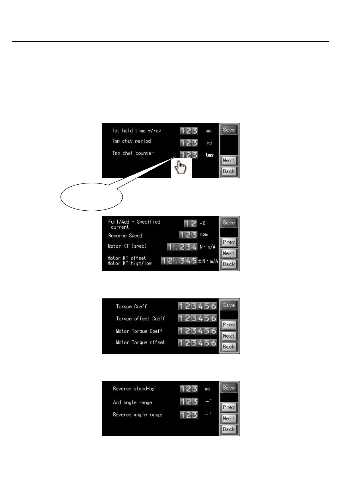
gment for
This is the parameter setting to use in the calculation of the current for
The specified percentage amount is subtracted from the full tightening
Set the KT value of the motor that is used. (Refer to the motor
to apply to the motor KT
■ Operation parameters
7.2 Screen display items
■ Screen display items (numeric input)
Numeric input item Description
1st hold time w/rev
(Holding time for first full tightening in
operation patterns that include reverse
rotation)
Tmp chat period
(Chattering judgment period for temporary
tightening)
Tmp chat counter
(Chattering judgment count for temporary
tightening)
Full/Add – Specified current
(Negative current value used for judgment
of whether the specified current is reached
in full tightening and additional tightening)
Set the holding time for the first full tightening in operation patterns that
include reverse rotation.
The unit is ms. * See Chapter 15 "Holding time".
Set the period of one scan in the current chattering jud
temporary tightening.
The unit is ms. * See Chapter 16.
Set the number of scans to perform in the current chattering judgment
for temporary tightening.
The unit is the number of times. * See Chapter 16.
the torque detection judgment, to speed up torque-up detection for full
tightening and additional tightening.
and additional tightening current.
The unit is -%.
Reverse Speed
(Reverse operation speed)
Motor KT (spec)
(Motor KT value (specification value))
Motor KT offset
Motor KT high/low
(Motor KT value offset
+ setting torque-down
- setting torque-up)
Torque Coeff
(Torque command correction slope
coefficient)
Torque offset Coeff
(Torque command correction offset value)
Motor Torque Coeff
Set the speed of the reverse operation. The unit is rpm.
specifications.)
The unit is N.m/A.
Set the positive and negative offset value
value.
This corrects for the difference between the motor torque and actual
tightening torque.
The unit is N.m/A.
This correction value is applied to the torque command to stabilize it.
(Perform calculation using the correction value calculation file.)
This correction value is applied to the torque command to stabilize it.
(Perform calculation using the correction value calculation file.)
This coefficient corrects for the difference between the motor torque
(Motor torque correction slope coefficient)
and actual tightening torque.
18 / 52

This setting specifies the required time, based on the angle and speed
This is the setting range of the required time, calculated from the angle
for the angle judgment in additional tightening. The
This is the range for the angle judgment in loosening. The setting range
The torque limit setting is changed based on the parameters specified
The unit is msec. * See Chapter 16.
■ Operation parameters
Motor Torque offset
(Wait time for angle judgment in loosening
operation)
Reverse stand-by
(Wait time for angle judgment in loosening
operation)
Add angle range
(Additional tightening angle judgment
range)
Reverse angle range
(Loosening angle judgment range)
Pattern 3, Reverse torque – Full
(Torque for pattern 3 loosening operation -
Negative percentage of full tightening
torque)
Torque down filter setting
1st step
(Torque-down filter setting -
Step 1 torque)
of the driver's loosening operation. The unit is ms.
and speed of the driver's loosening operation. The unit is ms.
This is the range
setting range is expressed in negative (-) degrees.
is expressed in negative (-) degrees.
This setting specifies the torque for the reverse rotation, in terms of
negative torque relative to the full tightening torque, to prevent
excessive looseness in the screw when the loosening operation in
pattern 3 is performed.
The unit is -%.
Set this parameter to reduce the spring-back of the bit that occurs
when the servo is turned OFF after the pattern is complete.
The torque limit setting is changed based on the parameters specified
for steps 1, 2, and 3, in that order.
The unit is %. * See Chapter 16.
Torque down filter setting
2nd step
(Torque-down filter setting -
Step 2 torque)
Torque down filter setting
3rd step
(Torque-down filter setting -
Step 3 torque)
Torque down filter setting Wait Time
(Torque-down filter setting -
Wait time)
Set this parameter to reduce the spring-back of the bit that occurs
when the servo is turned OFF after the pattern is complete.
The torque limit setting is changed based on the parameters specified
for steps 1, 2, and 3, in that order.
The unit is %. * See Chapter 16.
Set this parameter to reduce the spring-back of the bit that occurs when
the servo is turned OFF after the pattern is complete.
for steps 1, 2, and 3, in that order.
The unit is %. * See Chapter 16.
Set this parameter to reduce the spring-back of the bit that occurs
when the servo is turned OFF after the pattern is complete.
The wait time specifies the amount of time to wait before applying
each change to the torque limit setting.
19 / 52

■ Operation parameters
■ Screen display items (buttons)
Screen display
button
Description
Save the currently configured parameters.
If parameters have already been saved, the data is overwritten.
When saving is complete, the [特殊設定データ保存完了] (Finished saving special setting
data) message window is displayed.
[Next]/[Prev]
Display the next or previous page of the [HIOS] setting screen.
Return to the [Edit] screen.
Set whether or not to use the torque-down filter.
Select [ON] to reduce the spring-back of the bit that occurs when the servo is turned OFF
after the pattern is complete.
The torque limit setting is changed before the servo turns OFF upon completion of the pattern
operation.
The torque limit setting changes based on the parameters specified for steps 1, 2, and 3, in
that order.
The wait time specifies the amount of time to wait before applying each change to the torque
limit setting.
* See Chapter 16.
8. Operation parameters
The tables in this chapter describe the parameter settings for each operation pattern, as well as the available setting ranges
for the [Edit] screen and [HIOS] screen settings.
■ Parameter settings for each operation pattern
Operation No. Pattern 1 Pattern 2 Pattern 3 Pattern 4
Angle 1
(Rotation angle 1: °)
Angle 2
(Rotation angle 2: °)
Angle 3
Specified rotation angle for temporary tightening
Not used
Specified rotation
Specified rotation angle for loosening
Specified rotation
(Rotation angle 3: °) Not used
Rotation 1
(Rotation speed 1: rpm)
Speed for temporary tightening
angle for additional
tightening
20 / 52
Not used
angle for additional
tightening

■ Operation parameters
Rotation 2
Speed for full
Speed for full
Speed for full
(Rotation speed 2: rpm) Speed for full
tightening
Trq 1 (Torque 1: N.m) Torque for temporary tightening
Trq 2 (Torque 2: N.m) Torque for full tightening
Trq 3 (Torque 3: N.m) Not used Torque for additional
Cycle TM (Cycle time: s) Specified time for full set of operations of each pattern
Hold TM
(Holding time: ms)
Torque allowance
(Torque judgment range:
±%)
Counter
(Torque judgment
counter)
Holding time after torque-up for full tightening and additional tightening
* See Chapter 15 "Holding time"
Motor torque judgment range for full tightening and additional tightening
* See Chapter 16
Number of times to count full tightening and additional tightening torque judgment
* See Chapter 16
tightening and
additional tightening
tightening
tightening and
loosening
Not used Torque for additional
tightening,
loosening, and
additional tightening
tightening
■ Parameter setting range for operation patterns
Parameter name Description Default value Min. value Max.
Angle 1
(Rotation angle 1: °)
Angle 2
(Rotation angle 2: °)
Angle 3
(Rotation angle 3: °)
Rotation 1
(Rotation speed 1:
rpm)
Rotation 2
(Rotation speed 2:
rpm)
Specified rotation angle for temporary tightening
Specified rotation angle for loosening
Specified rotation angle for additional tightening
Speed for temporary tightening
Speed for full tightening, loosening, and additional
tightening
7200 1 59999
Pattern 3: 3
Pattern 4: 10
60 30 9999
800 10 2800
100 10 2800
1 9999
value
Trq 1
(Torque 1: N.m)
Trq 2
(Torque 2: N.m)
To rque for temporary tightening
0.300 0.300 1.300
0.300 0.300 1.300
Torque for full tightening
21 / 52

■ Operation parameters
Trq 3
Torque for additional tightening
(Torque 3: N.m)
3.000 0.300 1.300
Cycle TM
(Cycle time: s)
Hold TM
(Holding time: ms)
Torque allowance
(Torque judgment
range: ±%)
Counter Setting for number of times that normal motor torque value
* The minimum value is 30° because the torque-down causes the bit to spring back when the servo turns OFF after full
tightening is complete.
Specified time for full set of operations of each pattern
Holding time after torque-up for full tightening and
additional tightening
* See Chapter 15 "Holding time"
Motor torque judgment range for full tightening and
additional tightening
is detected, for screw tightening judgment.
30 5 100
150 50 500
5 1 99
10 1 100
22 / 52

rotation: ms)
Holding time setting for the first full tightening in
for temporary tightening: ms)
* See Chapter 16
number of times)
* See Chapter 16
additional tightening: -%)
rpm)
(Motor KT value: N.m/A)
(Refer to the motor specifications)
- setting torque-up)
The unit is N.m/A.
slope coefficient)
using the correction value calculation file.)
offset value)
using the correction value calculation file.)
slope coefficient)
torque.
offset value)
torque.
■ Operation parameters
■ Parameter setting range for special settings
Parameter name Description Default value Min. value Max.value
1st hold time w/rev
(Holding time for first full
tightening in operation
patterns that include reverse
Tmp chat period
(Chattering judgment period
Tmp chat counter
(Chattering judgment count
for temporary tightening:
Full/Add – Specified current
(Negative current value used
for judgment of whether the
specified current is reached
in full tightening and
operation patterns that include reverse rotation
* See Chapter 15 "Holding time"
Period setting of one scan in the current
chattering judgment for temporary tightening
Setting for number of scans to perform in the
current chattering judgment for temporary
tightening
Parameter setting used in the calculation of the
current for judgment to increase the torque-up
detection speed for full tightening and additional
tightening
100 50 500
1 1 50
5 0 100
10 0 50
Reverse Speed
(Reverse operation speed:
Motor KT (spec)
Motor KT offset
Motor KT high/low
(Motor KT value offset
+ setting torque-down
Torque Coeff
(Torque command correction
Torque offset Coeff
(Torque command correction
Motor Torque Coeff
(Motor torque correction
Speed setting for reverse operation
KT value setting of the motor that is used
Set the positive and negative offset value to
apply to the motor KT value.
This corrects for the difference between the
motor torque and actual tightening torque.
This correction value is applied to the torque
command to stabilize it. (Perform calculation
This correction value is applied to the torque
command to stabilize it. (Perform calculation
This coefficient corrects for the difference
between the motor torque and actual tightening
200 1 999
0.42 0.001 1.000
0 -1.000 1.000
Factory
setting
Factory
setting
Factory
setting
-32768 32767
-32768 32767
-32768 32767
Motor Torque offset
(Motor torque correction
This offset value corrects for the difference
between the motor torque and actual tightening
23 / 52
Factory
setting
-32768 32767

■ Operation parameters
Reverse stand-by
(Wait time for angle judgment
in loosening operation)
This is the setting range of the required time,
calculated from the angle and speed of the
driver's loosening operation. The unit is ms.
100 0 999
Add angle range
(Additional tightening angle
judgment range)
Reverse angle range
(Loosening angle judgment
range)
Pattern 3, Reverse torque –
Full
(Torque for pattern 3
loosening operation -
Negative percentage of full
tightening torque)
Torque down filter setting
1st step
(Torque-down filter setting -
Step 1 torque)
Torque down filter setting
2nd step
(Torque-down filter setting -
Step 2 torque)
Torque down filter setting
3rd step
(Torque-down filter setting -
Step 3 torque)
Torque down filter setting
Wait Time
(Torque-down filter setting -
Wait time)
This is the range for the angle judgment in
additional tightening.
The setting range is expressed in negative (-)
degrees.
This is the range for the angle judgment in
loosening.
The setting range is expressed in negative (-)
degrees.
This setting specifies the torque for the reverse
rotation, as negative torque relative to the full
tightening torque, to prevent excessive
looseness in the screw when the loosening
operation in pattern 3 is performed.
The unit is -%.
This parameter is set to reduce the spring-back
of the bit that occurs when the servo is turned
OFF after the pattern is complete. The torque
limit setting is changed based on the parameters
specified for steps 1, 2, and 3, in that order.
The unit is N.m. * See Chapter 16.
This parameter is set to reduce the spring-back
of the bit that occurs when the servo is turned
OFF after the pattern is complete. The torque
limit setting is changed based on the parameters
specified for steps 1, 2, and 3, in that order.
The unit is N.m. * See Chapter 16.
This parameter is set to reduce the spring-back
of the bit that occurs when the servo is turned
OFF after the pattern is complete. The torque
limit setting is changed based on the parameters
specified for steps 1, 2, and 3, in that order.
The unit is N.m. * See Chapter 16.
This parameter is set to reduce the spring-back
of the bit that occurs when the servo is turned
OFF after the pattern is complete. The wait time
specifies the amount of time to wait before
applying each change to the torque limit setting.
The unit is msec. * See Chapter 16.
10 0 999
10 0 999
0 0 100
0.000 0.000 5.500
0.000 0.000 5.500
0.000 0.000 5.500
0 0 999
24 / 52

tightening torque)
The unit is -%.
The unit is N.m. * See Chapter 16.
The unit is N.m. * See Chapter 16.
The unit is N.m. * See Chapter 16.
The unit is msec. * See Chapter 16.
■ Operation parameters
Pattern 3, Reverse torque –
Full
(Torque for pattern 3
loosening operation -
Negative percentage of full
This setting specifies the torque for the reverse
rotation, as negative torque relative to the full
tightening torque, to prevent excessive
looseness in the screw when the loosening
operation in pattern 3 is performed.
0 0 100
Torque down filter setting
1st step
(Torque-down filter setting -
Step 1 torque)
Torque down filter setting
2nd step
(Torque-down filter setting -
Step 2 torque)
Torque down filter setting
3rd step
(Torque-down filter setting -
Step 3 torque)
This parameter is set to reduce the spring-back
of the bit that occurs when the servo is turned
OFF after the pattern is complete. The torque
limit setting is changed based on the parameters
specified for steps 1, 2, and 3, in that order.
This parameter is set to reduce the spring-back
of the bit that occurs when the servo is turned
OFF after the pattern is complete. The torque
limit setting is changed based on the parameters
specified for steps 1, 2, and 3, in that order.
This parameter is set to reduce the spring-back
of the bit that occurs when the servo is turned
OFF after the pattern is complete. The torque
limit setting is changed based on the parameters
specified for steps 1, 2, and 3, in that order.
0.000 0.000 5.500
0.000 0.000 5.500
0.000 0.000 5.500
Torque down filter setting
Wait Time
(Torque-down filter setting -
Wait time)
This parameter is set to reduce the spring-back
of the bit that occurs when the servo is turned
OFF after the pattern is complete. The wait time
specifies the amount of time to wait before
applying each change to the torque limit setting.
0 0 999
25 / 52

■ Operation timing charts
9. Operation pattern timing charts
This chapter describes the timing charts for each operation pattern.
■ Pattern 1
26 / 52

■ Operation timing charts
■ Pattern 2
27 / 52

■ Operation timing charts
■ Pattern 3
28 / 52

■ Operation timing charts
■ Pattern 4
29 / 52

Select
■ I/O
10. Manual/auto mode
In manual mode, the screw tightening operation starts when the [Start] button is touched, after selecting the rotation direction
([CW]/[CCW] (Clockwise)/(Counterclockwise)) for the channel No. and pattern No. on the [Program Preview] screen.
In auto mode, the screw tightening operation starts when the [Start] switch is turned ON, after selecting the rotation direction
([CW]/[CCW] (Clockwise)/(Counterclockwise)) for the channel No. and pattern No. using the external I/O switches.
■ Manual mode
Fig.8-1 [Program Preview] screen (1/2)
Start operation
Fig.8-2 [Monitor Operate] screen
30 / 52

(counterclockwise)
mode]
Screwdriver
External I/O switches
PTN No
CH No
CW/CCW
Auto/Manual
Start
■ I/O
■ Auto mode
11. I/O
11.1 I/O allocation table
■ I/O input signals
Signal Signal name Contact Input
IN0 Start IN A OFF→ON ON: Operation starts [Enabled in auto mode]
Start operation
Touch panel
Fig.8-3 Auto mode configuration
signal
Description
IN1 FOR/REV switching IN A Level
IN2 Auto/Manual switching IN A Level OFF: Manual, ON: Auto
IN3 CH1 IN A OFF→ON CH No. bit 0 [Enabled in auto mode]
IN4 CH2 IN A OFF→ON CH No. bit 1 [Enabled in auto mode]
IN5 CH4 IN A OFF→ON CH No. bit 2 [Enabled in auto mode]
IN6 CH8 IN A OFF→ON CH No. bit 3 [Enabled in auto mode]
IN7 PTN1 IN A OFF→ON PTN No. bit 0 [Enabled in auto mode]
IN8 PTN2 IN A OFF→ON PTN No. bit 1 [Enabled in auto mode]
IN9 PTN4 IN A OFF→ON PTN No. bit 2 [Enabled in auto mode]
IN10 Temporary/Full tightening
switching IN
IN11 - - -
IN12 Alarm reset IN A OFF→ON ON: Reset alarm when alarm occurs
IN13 Emergency stop IN A OFF→ON ON: Stop shaft rotation and generate an error
IN14 Torque judgment display clear
IN
A OFF→ON
A OFF→ON
OFF: FOR (clockwise), ON: REV
ON: Switch to full tightening operation, when
temporary tightening operation is being performed
-
ON: Clear the torque judgment display on the touch
panel
IN15 Reverse IN A OFF→ON
ON: Start the reverse operation [Enabled in auto
31 / 52

■ I/O
■ I/O output signals
Signal Signal name Contact Output
signal
OUT0 Start OUT A OFF→ON ON: Operation has started
OUT1 Finish OUT A OFF→ON ON: Finish operation
OUT2 FOR/REV OUT A Level OFF: FOR (clockwise), ON: REV
(counterclockwise)
OUT3 Busy OUT A Level OFF: Not operating, ON: Operating
OUT4 Error 1 OUT A OFF→ON ON: SVD error
OUT5 Error 2 OUT A OFF→ON ON: Operation error
OUT6 Error 3 OUT A OFF→ON ON: SVC error
OUT7 Error 4 OUT A OFF→ON ON: Operation error (only when torque judgment is
NG)
OUT8 Reserved
OUT9 Reserved
OUT10 Torque judgment OK OUT A OFF→ON ON: Torque judgment is OK
OU T 11
Description
OUT12
OUT13
OUT14
OUT15
11.2 I/O input signal reception time table
■ I/O input signals
Signal Signal name Min. reception time (msec) Notes
IN0 Start IN 100 Received only while shaft is stopped
IN1 FOR/REV switching IN 100 Received only while shaft is stopped
IN2 Auto/Manual switching IN 100 Received only while shaft is stopped
IN3 CH1 IN
IN4 CH2 IN
IN5 CH4 IN
IN6 CH8 IN
IN7 PTN1 IN
Applied when start I/O is ON
Applied when start I/O is ON
Applied when start I/O is ON
Applied when start I/O is ON
Applied when start I/O is ON
IN8 PTN2 IN
IN9 PTN4 IN
IN10 Temporary/Full tightening
switching IN
100 Received only while temporary tightening is
32 / 52
Applied when start I/O is ON
Applied when start I/O is ON
performed

■ I/O
IN11 Return to 0 position IN 100 Received only while shaft is stopped
IN12 Alarm reset IN 100 Received only while alarm occurs
IN13 Emergency stop IN 100 Always received
IN14 Torque judgment display clear IN 100 Always received
IN15 Reverse IN 100 Received only while shaft is stopped
33 / 52

■ I/O
11.3 I/O input signal sequence
■ Sequence of each input control signal
IN0 (Start IN)
Start enable conditions: - When in auto mode
- When CH No has been set
- When alarm reset IN (IN 12) is OFF
IN1 (FOR/REV switching IN)
Switch enable condition: When in auto mode
FOR (clockwise): Enables screw tightening direction, REV (counterclockwise): Enables screw loosening direction
IN2 (Auto/Manual switching IN)
Switches between auto mode and manual mode
IN3 (CH1 IN) to IN6 (CH8 IN)
Enable condition: When in auto mode
The channel number is selected based on the specified bit.
IN7 (PTN1 IN) to IN9 (PTN4 IN)
Enable condition: When in auto mode
The pattern number is selected based on the specified bit.
IN10 (Temporary/Full tightening switching IN)
Switches to full tightening operation, when temporary tightening operation is being performed.
IN12 (Alarm reset IN)
Alarm is reset if an alarm has occurred.
IN13 (Emergency stop IN)
If the shaft is in operation, the shaft rotation stops and an error is generated.
IN14 (Torque judgment display clear IN)
The judgment message displayed on the touch panel is cleared.
IN15 (Reverse IN)
Enable condition: When in auto mode
The screwdriver rotates in the screw loosening direction only while the signal is ON.
34 / 52

■ I/O
■ Output status signals
OUT0 (Start OUT)
The status of the screw tightening operation is indicated.
The indicator lights up while the screw tightening operation is being performed.
OUT1 (Finish OUT)
The status of the screw tightening operation is indicated.
The indicator lights up for 100 ms after the screw tightening operation is complete.
OUT2 (FOR/REV OUT)
The current clockwise/counterclockwise setting is output.
OUT3 (Busy OUT)
The current operation status is output.
ON is output when shaft is in operation, and OFF is output when the shaft is stopped.
OUT4 (Error 1 OUT)
Output is performed when an SV-NET driver error occurs.
OUT5 (Error 2 OUT)
Output is performed when an operation error occurs.
OUT6 (Error 4 OUT)
Output is performed when an SV-NET controller error occurs.
OUT7 (Error 8 OUT)
Output is performed only when operation error with NG torque judgment occurs.
OUT10 (Torque judgment OK OUT)
Output is performed only when torque judgment is OK after operation is complete.
35 / 52

■ I/O
11.4 I/O input timing charts
■ Timing chart for normal operations when torque judgment is OK
36 / 52

■ I/O
■ Timing chart for normal operations when torque judgment is NG
37 / 52

■ I/O
■ Timing chart when emergency stop signal is input
38 / 52

■ Message window
12. Message window
The message window is displayed when data loading or saving is complete, and for events such as the torque judgment after
screw tightening.
To close the message window, touch the top part of the window or turn ON the IN14 signal of the external I/O.
■ Displayed messages
Fig.12-1 [Finished loading data] message window
Fig.12-2 [Torque judgment OK] message window (Pattern 1)
Fig.12-3 [Torque no good] (Torque judgment NG) message window (Pattern 1)
[Torque less than set] (Below motor torque setting)
Fig.12-4 [Torque judgment OK, additional tightening angle judgment OK] message window (Pattern 2)
39 / 52

■ Message window
Fig.12-5 [Torque judgment NG, additional tightening angle judgment OK] message window (Pattern 2)
Fig.12-6 [Torque judgment OK, additional tightening angle judgment NG] message window (Pattern 2)
Fig.12-7 [Below additional tightening torque setting, additional tightening angle judgment OK] message window (Pattern 2)
Fig.12-8 [Torque judgment OK, loosening angle judgment OK] message window (Pattern 3)
Fig.12-9 [Torque judgment NG, loosening angle judgment OK] message window (Pattern 3)
40 / 52

■ Message window
Fig.12-10 [Torque judgment OK, loosening angle judgment NG] message window (Pattern 3)
Fig.12-11 [ Torque judgment NG, loosening angle judgment OK] message window (Pattern 3)
Fig.12-12 [Torque judgment OK, additional tightening angle judgment OK, loosening angle OK] message window (Pattern 4)
Fig.12-13 [Torque judgment NG, additional tightening angle judgment OK, loosening angle OK] message window (Pattern 4)
41 / 52

■ Message window
Fig.12-14 [Torque judgment OK, loosening angle judgment OK, additional tightening angle NG] message window (Pattern 4)
Fig.12-15 [Torque judgment NG, additional tightening angle judgment OK, loosening angle OK] message window (Pattern 4)
Fig.12-16 [Torque judgment OK, additional tightening angle judgment OK, loosening angle NG] message window (Pattern 4)
Fig.12-17 [特殊設定データ保存完了] (Finished saving special setting data) message window
42 / 52

■ Message window
■ Message list
Message Description
Data loaded Finished loading the parameter settings.
Data saved Finished saving the parameter settings.
特殊設定データ保存完了
(Finished saving special setting data)
Torque OK
(Torque judgment OK)
Torque no good
Torque more than set
(Torque judgment NG -
Above motor torque setting)
Torque no good
Torque less than set
(Torque judgment NG -
Below motor torque setting)
No torque judgment Displayed when screw is rotated to specified angle before torque-up is detected,
Additional tightening angle When the additional tightening operation is performed in patterns 2 and 4, the
Finished saving the parameters of special settings.
The torque detection value is within the setting range.
* The torque is not displayed if the judgment count is set to 0.
The motor torque detection value is above the upper setting limit.
The motor torque detection value is below the lower setting limit.
when performing additional tightening to specified angle.
Only the most recent motor torque value is displayed.
value specified for [Angle 3] (Rotation angle 3) on the touch panel display is used
to judge the angle of rotation after the torque-up of additional tightening.
Loosening angle When the loosening operation is performed in patterns 3 and 4, the value
specified for [Angle 2] (Rotation angle 2) on the touch panel display is used to
judge the angle of rotation in the loosening operation.
43 / 52

■ System settings
13. System settings
On the touch panel VT3 system settings screen, you can change the password and set whether or not a sound is emitted
when buttons are touched.
In addition, the system settings screen can be used to monitor the device, by checking the total number of screw tightening
OK judgments.
■ Displaying the system settings screen
To display the system settings screen on the touch panel, first place a finger on the screen where there are no other buttons
for at least 3 seconds, then remove your finger for less than 1 second and touch the top right edge of the touch panel screen.
* For more information, refer to Chapter 9 "Special operations screen" in the "VT3_Hardware.pdf".
■ Checking the screw tightening OK judgment count
You can check the total number of screw tightening OK judgments by viewing the MW07FE and MW07FF built-in touch panel
devices in [デバイスモニタ] (Device monitor) on the system settings screen.
MW07FE: The count increases by 1 for each 10,000 OK judgments. (Unit: 10,000 times)
MW07FF: The count increases by 1 for each OK judgment, and the count is reset to 0 when the count reaches 10,000. (Unit:
1 time)
* For more information, refer to Chapter 5 "System modes" in the "VT3_Hardware.pdf".
Note: When TP project data is transferred, all device values are reset (judgment counts are set to 0).
■ Checking the total number of screw tightening OK judgments
[Total No. of fastened Counter] (Total count monitor for screw tightening OK judgments - OK judgment counter)
■ You can check the total number of times that the screw tightening OK judgment has been counted.
44 / 52

■ Button touch operations
14. Button touch operations
The [Rev], [Manual], [Auto], [CW], [CCW], [Torque down filter setting] buttons have an ON delay of 0.5 second.
The buttons do not respond unless they are touched for at least 0.5 second.
The [Load], [Save], [Start], [Stop], [Error Reset], and [HIOS] buttons have an OFF delay of 0.5 second.
When these buttons are pressed, other buttons do not respond for 0.5 second.
45 / 52

■ Holding time
15. Holding time
■ Holding time setting
The holding time setting range is from a minimum of 50 msec to a maximum of 500 msec.
Each screw tightening judgment takes several msec, so when the number of judgments is increased, the actual torque
holding time may become longer than the setting, depending on the holding time value that is specified. When increasing
the number of judgments, it is also necessary to specify a longer holding time.
When using chattering judgment for temporary tightening, a higher temporary tightening speed results in a longer torque
holding time.
When using chattering judgment for temporary tightening, a smaller difference between the temporary tightening torque
and full tightening torque results in a longer torque holding time.
46 / 52

■ Detailed pattern diagrams
16. Detailed pattern diagrams
■ Chattering judgment
Details of chattering judgment
47 / 52

■ Detailed pattern diagrams
■ Screw tightening judgment
Details of screw tightening judgment
■ Torque-down filter
Details of torque-down filter
48 / 52

■ Alarms
17. Alarms
If a device error occurs or the results of the screw tightening judgment are NG, the error No. is displayed on the [Operate]
screen, and the touch panel screen flashes to indicate that an error has occurred.
To cancel the alarm, remove the cause of the error, then touch the [Error Reset] button on the [Operate] screen or [Monitor
Operate] screen, or turn ON the IN12 signal of the external I/O. The details for each error No. are shown in the error list below.
17.1 Error list (motor driver errors)
Error
Name Description Status Cause Solution
No.
11 Over Current Error or
excessive
current in
power drive
21 Over Load Overload
alarm
Occurs only when
power is turned ON
Occurs when servo is
turned ON
Occurs when
accelerating/decelera
ting
Motor vibrates when
servo is turned ON or
while in operation
Occurs when
Driver malfunction Replace driver
Short-circuit in motor
wiring
Short-circuit in motor
winding
Driver failure Replace driver
Poor driver adjustment Lower the gain
Driver failure Replace driver
Poor adjustment Readjust the gain
Acceleration/deceleration
Check motor wiring
Replace motor
Reduce the
accelerating/decelera
ting
Occurs at a particular
rotation speed
Occurs when servo is
turned ON
31 Over Speed Speed alarm Occurs while in
operation
41 Counter
Overflow
Multi-rotation
error
Occurs while motor is
rotating
speed is too high
The load torque is too
high
Motor wiring Check motor wiring
Speed limit is exceeded Readjust the gain
Multi-rotation data of
resolver exceeded the
specified value
acceleration/deceleration
speed
Check the mechanical
parts/
Increase the motor size
Set the amount of
movement from the origin
to within 7,000,000 hex
count/
Initialize the sensor/
Enable unlimited rotation
49 / 52

■ Alarms
42 Excess
Value of
Occurs at pulse
Pulse was input without
Check the servo ON
position
deviation
Error list (motor driver errors)
Error
Name Description Status Cause Solution
No.
51 Over heat Abnormal
deviation
counter
exceeded the
specified
value
temperature
of power
drive was
detected
command input
Occurs when
accelerating/decelera
ting
Occurs while in
operation
turning servo ON
The F-LMT and R-LMT
signals are not input or
configured
Acceleration/deceleration
speed is too high
Frequent use while
overloaded
Ambient temperature is
high
signal
Check the wiring and
settings
Reduce the
acceleration/deceleration
speed
Relax the operating
conditions
Install a fan or other
device to improve heat
dissipation
61 Sensor Error Sensor error When power is
turned ON
62 Detected excessively
71 Over Voltage Excess drive
voltage
Occurs while in
operation
Occurs when power
is turned ON
Detected small amplitude
of resolver signal
large amplitude of
resolver signal
Insufficient regeneration
ability
If detected when power is
turned ON, the voltage
Turn up the sensor
excitation voltage one step
Turn down the sensor
excitation voltage one step
Insufficient power supply
capacity:
Add regeneration
protection circuit to power
supply/
Insufficient regeneration
protection ability:
Reduce the deceleration
speed
Change the driver
specifications are not
suitable.
Driver failure Replace driver
Sometimes detected
when using
50 / 52
Driver detects voltage of
regeneration protection
Increase the value of
ID205 "Excess voltage

■ Alarms
regeneration unit
operation error detection voltage"
72 Voltage Down Low drive
voltage
91 Flash Memory
Error
92 Non-volatile
Error list (motor driver errors)
Non-volatile
memory read
error
memory write
error
TA8413 with 48 V
power supply
During operation Insufficient power supply
capacity
Disconnection in drive
power supply line
When power is
turned ON
When power is
turned ON
When writing the
parameters
Disconnection in drive
power supply line
Failure of non-volatile
memory or CPU in
integrated circuit
(upper limit: 65 V)
Add regeneration
protection circuit to power
supply
Check wiring
Replace driver
Error
No.
98 Hardware
Error
99 Parameters
Error
Name Description Status Cause Solution
CPU error Occurs while in
operation
When power is
turned ON
Parameter
error
When writing the
parameters
Incorrect operation due to
noise
Driver malfunction Replace driver
Abnormal values when
writing the parameters to
non-volatile memory
(writing is not performed)
Install a noise filter
Check the values of the
parameter settings that
were changed
51 / 52

■ Alarms
17.2 Error list (operation errors)
Error
No.
100 Screw
102 Torque
103 I/O input NG External I/O
Name Description Status Cause Solution
Screw
tightening
operation
error
judgment NG
tightening
operation
error
Torque
judgment NG
CH No and
external I/O
PTN No entry
Emergency stop
button was pressed
Screw tightening time
was exceeded
Torque judgment
result is NG
The channel No. and
pattern No. from the
external I/O have not
been selected
Emergency stop button
was pressed
The time of the operation
exceeded the time set for
the screw tightening cycle
Detected a value outside
the upper or lower limit of
the range, in the screw
tightening torque
judgment
Input error Perform error reset, then
Check the device status
and perform error reset
Check the device status
and perform error reset
Check the device status
and perform error reset
enter the external I/O
channel No. and pattern
No.
104 Angle
judgment NG
17.3 Error list (SVC errors)
Error
No.
200
+ SVC
error
No.
Name Description Status Cause Solution
SVC error SVC error Error occurred in SV-
omission
Screw
tightening
operation
error
Error in additional
tightening angle or
loosening angle
NET controller.
The error No. is 200
+ the SVC error No.
Occurs if the angle does
not reach the angle
specified when pattern 2,
3, or 4 is set
Controller program error,
etc.
Specify the angle again
when pattern 2, 3, or 4 is
set
Refer to the user's manual
for the SV-NET controller.
52 / 52
 Loading...