

HIOS CLT-AY-61, CLT-AY-81 Operation Manual

Transformer with Automatic
Controlled Systems
For Electric Screwdrivers
Operation Manual
CLT-AY-61, CLT-AY-81
(March. 2017)
HIOS Inc
.
1-16-5 Akiyama, Matsudo City, Chiba Pref., Japan
Phone: +81-47-392-2001
FAX: +81 47 392 7773
Operation Manual No. ET-A035
17A

1
Thank you very much for your purchase the Transformer Model: CLT-AY-61, CLT-AY-81.
Before starting the operation, read this manual to use CLT-AY-61and CLT-AY-81 safely and
properly.
This manual should be kept and read always. If in case of trouble, confirm the phenomenon’s by
This manual and contact us soon.
Table of Contents
Cautions in Operation 2
Selection of Controllers 2
Name of Each Part 3-4
Setting of switches on the PCB 5
Input and Output circuit 6
Timing Chart for Pulse input starting system 7
Timing Chart for Reading starting system 8
Timing Chart of Option: REV Starting System
9
Timing Chart of Option: 2WV Starting System 9
Notice of using Transformer for Multiple Axes 10
Procedure of Setting and Installation 10
Power supply for Automatic screwdriver: Specification 11
Dimension 12
China RoHS2 Table 13
2
Cautions in Operation
*Before operating this transformer, read this manual for proper and safety use.
*Use this transformer under the proper voltage.
*Use in a well-ventilated place.
*This transformer must be place in the clean and dry room and kept away from oil, corrosive gas,
Interference noise, high voltage unit and the like.
*Note the lot number and inspection sheet number.
*Before operation, this transformer must be grounded.
*Spare transformer in order to avoid the unnecessary rotation of driver
*Set the proper overtime for tightening screw to work the reset function of the transformer in
order to avoid the unnecessary rotation of driver.
*If the overtime continues, resolve the cause and re-start the unit.
*When you install the unit, allow some slack for wiring of control terminal or power code.
However, too much slack or unreasonable wiring: ex. binding the power code and signal wires
together will be cause of trouble.
*This unit should be installed in the system where it can be easily seen and removed.
*Whenever the change of I/O setting or replacement of unit, the power code must be unplugged
And confirmed the safety of all systems. All setting must be same before and after replacement.
*Use this transformer only for control the
designated automatic driver manufactured by HIOS.
Note
: Never use this for the manual drivers. It may cause trouble.
Model
Driver moldes can
be connected
CLF-3000(HH/HN)
CLF-4000 (HH, XH/HN, XN)
CLF-6000 (HH, XH/HN, XN)
CLF-6500 (HH, XH/HN, XN)
CLF-7000 (HH, XH/HN, XN)
αF-4500 (HH, XH/HN, XN)
αF-5000 (HH, XH/HN, XN)
αF-6500 (HH, XH/HN, XN)
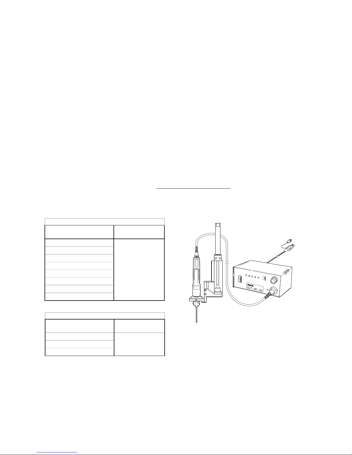
●For CLT-AY-61 Applicable automatic driver
1 driver only
Model
Driver moldes can
be connected
CL-816(XH/XN)
CL-825A(XH/XN)
CL-815A(XH/XN)
●For CLT-AY-81 Applicable automatic driver
1 driver only
3
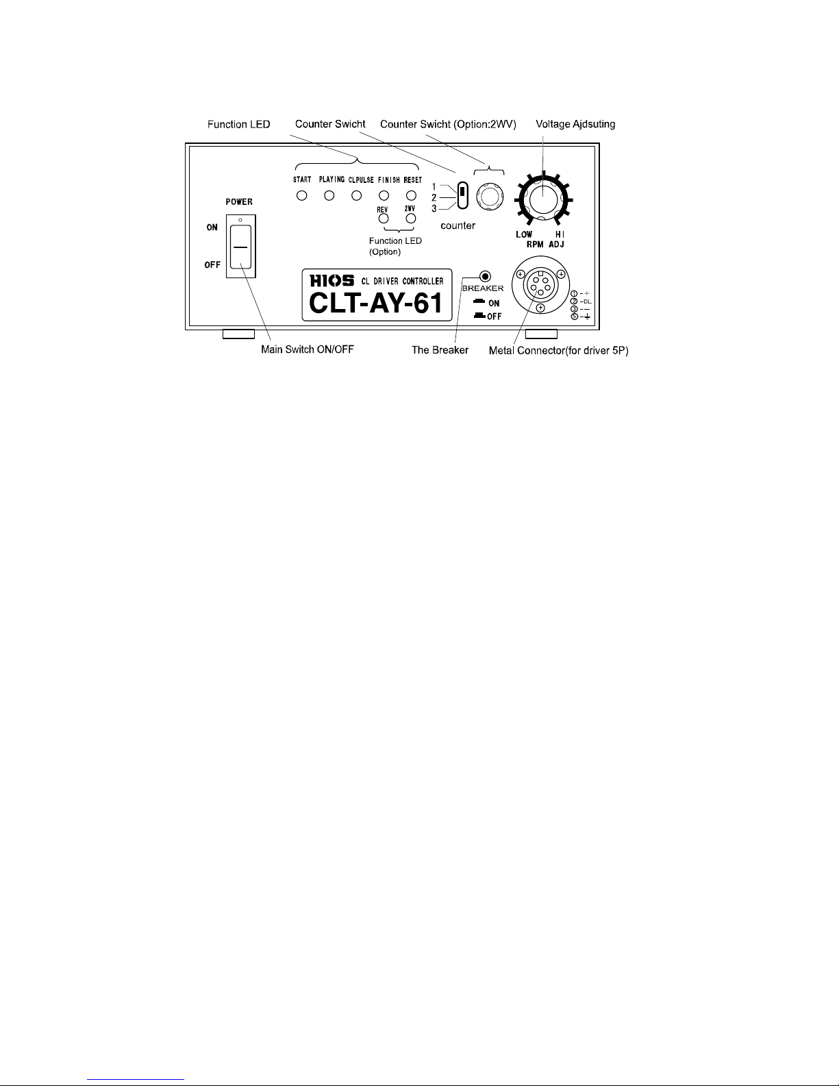
Name of Each Part
●
Front Panel (CLT-AY-81 is similar to CLT-AY-61)
Main Switch: ON and OFF AC100, 120V or 220 - 240V Power with is brought to Transformer.
Function Leeds:
START : This lamp turns on while the START signal is input.
PLAYING : This lamp turns on while the START driver rotates.
CL PULSE : This lamp indicates that the pulse signal output when the torque detection SW of
driver detects the torque. The rotation of diver will also be stopped by this pulse
signal provided to the transformer.
FINISH : This lamp turns on when the screw tightening is finished. And it keeps lighting until
the next starting or reset command is executed.
RESET : This lamp turns on while any trouble is occurred on tightening or overtime condition.
*Note; In case that output circuit is short or load is over, CL PULSE and RESET LEDs turn on
simultaneously and output to the motor of driver will be stopped. In such case, check
the driver.
OPTIONS
(Followings are optional specifications.)
2WV : This lamp turns on while the driver works at Low Level of rotation, described at the
optional LOW-HI specifications.
REV : This lamp turns on while the driver works at Reverse rotation, described at the optional
REV specifications.
COUNTER SW : Number of the impact for completion of tightening is selected
By this SW; 1= 1 time of impact
2= 2 time of impact
3= 3 time of impact
Voltage Adjusting
Dial : You can adjust the times of rotation steplessly in a provided range.
Circuit Breaker : This protects the secondary side (driver, circuit) of transformer.
4
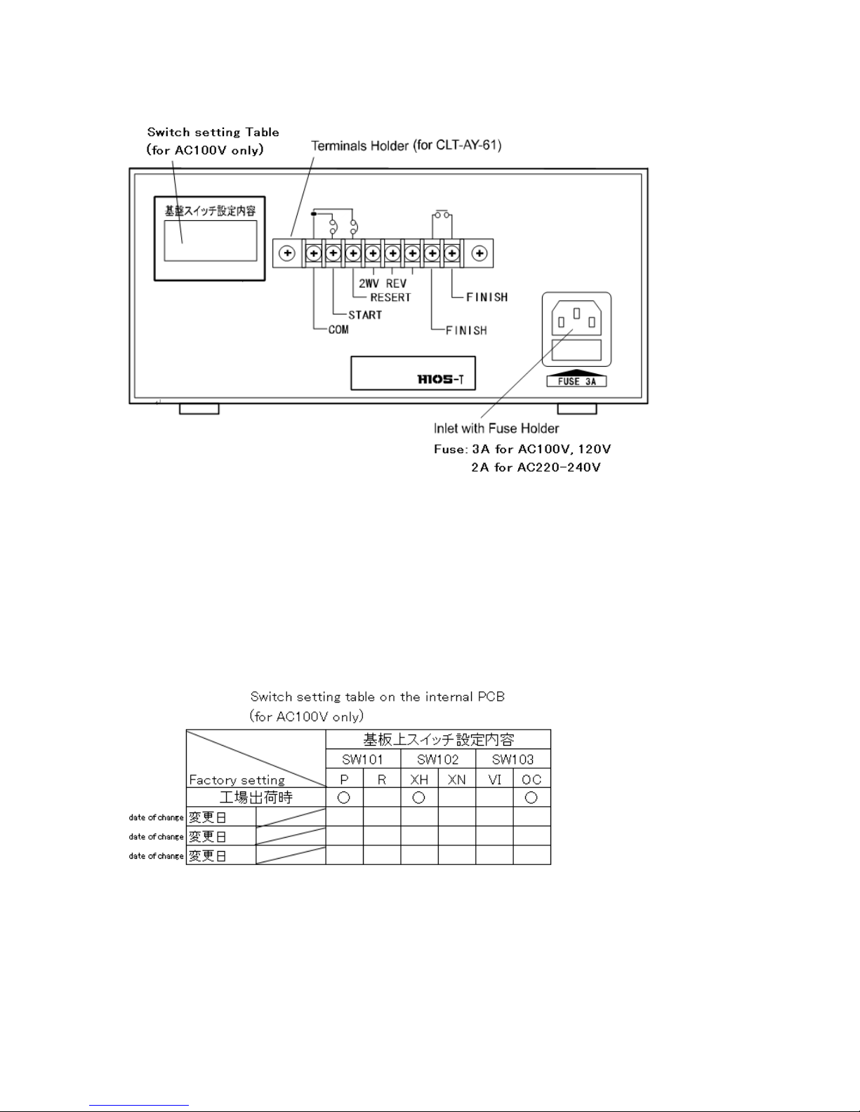
●
Rear Panel (Terminal location of CLY-AY-81 is different from CLT-AY-61 but same function)
Terminal :Connect Input and/or Output cables.
Terminal is removable by unscrewing 2 screws at the both end of the terminal.
When you do it, unscrew each of screw little by little.
The table below is the status of switches of the PCB set at HIOS factory.
If you change the setting, refer to the section of “Input/Output setting”
Fuse Holder : 1 each of Fuse and Spare Fuse are installed.
If the Fuse is cut then the lamp of AC Switch and LED lamps do not lit,
replace with Spare Fuse.
 Loading...