

HIOS BLT-AY-61, BLT-AY-71 Operation Manual

Driver Controller for Automatic
BLF Brushless Screwdriver
BLT-AY-61
BLT-AY-71
Operation Manual
(As of September of 2017)
HIOS Inc.
1-16-5 Akiyama, Matsudo City, Chiba Pref., Japan 270-2223
Phone: 81-47-392-2001 FAX: 81-47-392-7773
No. ET-A048
17B

- 2 -
Contents
■ Introduction ........................................................................................................................................... 3
■ Outline ...................................................................................................................................................... 4
■ Precautions ............................................................................................................................................. 5
■ BLT-AY-61/BLT-AY-71 Specications ............................................................................................ 6
■ Exterior Drawings ................................................................................................................................ 7
■ Main Functions ..................................................................................................................................... 8
■ Main Terminology ............................................................................................................................... 9
■ Front Panel ............................................................................................................................................. 10
■ Rear Panel Input / Output ................................................................................................................ 11
■ Display When the Power is ON with the Default Settings ................................................... 12
■ How to switch between Reading Start/Pulse Start ................................................................ 13
■ MODE Settings 1 .................................................................................................................................. 14
■ MODE Settings 2 .................................................................................................................................. 15
■ Torque Up Settings ............................................................................................................................. 16
■ Clutch Mechanism ............................................................................................................................... 17
■ Input / Output Connections ............................................................................................................ 18
■ Relationship between RPM and Torque ..................................................................................... 19
BLF-2000, BLF-5000
■ Relationship between RPM and Torque ..................................................................................... 20
BLF-7000 Series
■ Timing Chart Table .............................................................................................................................. 21
■ Timing Chart 01-18 ............................................................................................................................. 22-39
■ After-sale service .................................................................................................................................. 40
- 3 -
■ Introduction
Thank you for purchasing the BLT-AY-61 and BLT-AY-71 Driver controller. Please read this
instruction manual thoroughly before use to ensure proper operation. Store this instruction
manual in a safe place for future reference.
BLT-AY-71 is only up to 120V ac for warranty more then 120V ac, HIOS can not take any responsibility.
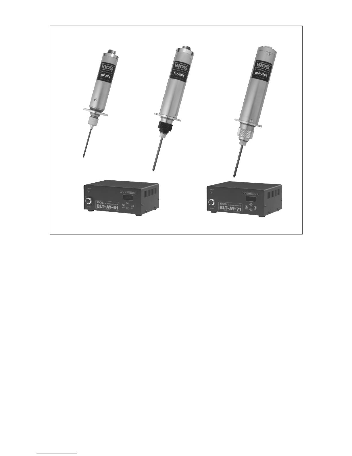
BLF-2000 BLF-5000 BLF-7000 Series
BLT-AY-61 BLT-AY-71

- 4 -
■ Outline
Conventional automatic screw drivers of CLF Series, αF Series, and CL-A Series use motors with
carbon brushes that require periodic replacement. Wear in the carbon brushes as well as in the
commentator aects the operating life of the driver, requiring the motor to be replaced periodically.
The BLT-AY-61 and BLT-AY-71 Driver controller uses a brushless motor and not use consumable
parts such as carbon brush. That saves much of maintenance eorts for this driver.
Features such as 2WS* (2-way speed) and REV (reverse rotation), which are available as optional for CLT-AY-61/CLT-AY-81, are now included as standard.
A torque protection circuit is used during low speed 2WS operation to vastly improve bit stopping when re-tightening screws.
There is a main power switch, and the primary input voltage ranges from 100 V to 240 V allowing worldwide use.
* With conventional Driver controller CLT-AY-61/CLT-AY-81, similar function is called "2WV", but with these new
automatic drivers, it is called "2WS".
<Notes>
① BLT-AY-61 is a power supply dedicated to BLF-2000 and BLF-5000.
② BLT-AY-71 is a power supply dedicated to BLF-7000 series. Up to
120V ac only.
③ Any other power supply or counter, such as T-70BL or BLOP-STC3,
cannot be used for automatic screwdrivers.
Such misuse might cause an accident or other problem.
(Notice)
We can specially provide you with a screwdriver for left-handed threads on request.

- 5 -
■ Precautions
Please read this instruction manual thoroughly before use to ensure proper operation.
● On any commercial power source, install a ground-fault interrupt breaker and safety circuit
breaker.
● Connect the unit to ground and use only the rated voltage.
● Do not exceed the rated loads for the output connections on the rear panel. Exceeding the
rated load will cause the unit to malfunction.
● If the unit may be subjected to inductive loads from a relay or solenoid valve coil in auxiliary
equipment connected to the input/output connections on the rear panel, install a reverse
polarity diode to suppress electrical noise. The unit may malfunction if noise suppression is
not installed.
● The overload protection will be activated when the driver is locked or has become overloaded. If the driver is overloaded repeatedly, the maximum ratings of the unit or attached
electric driver may be exceeded. If the driver becomes overloaded during Forward operation
or begins to malfunction due to developing excessive heat, stop the ongoing operation immediately, turn the main power switch o, remove the power cable, and contact our service
department for repairs.
● When tightening screws on work pieces constructed of plastics susceptible to static electricity build-up, tightening should be performed after static electricity has been discharged. If
working on pieces that have not been properly discharged, static electricity may flow up
through the end of the bit, causing malfunctions.
● A common GND should be used if the unit is connected to auxiliary equipment that is powered separately. The unit may malfunction if a common GND is not used.
● Do not apply voltage to the inputs or outputs. This may cause malfunctions.
● Extending input/output connection cables longer than necessary or bundling power cables
together can cause malfunctions.
● Choose an installation area with no vibrations. If the unit is installed in a high location, ensure that it is properly secured.
● Do not install the unit near high voltage equipment or in an electrically noisy environment.
● Do not place heavy items on top of the unit, or stack the units on top of one another.
● Do not install the unit in an area where it may be subjected to dust or metal fragments.
● Do not use the unit with anything other than HIOS drivers as this will cause the unit to malfunction.
● Do not disassemble or modify the unit in any way, as doing so may cause the unit to malfunction. Such malfunctions are not covered by the HIOS warranty and repairs to the unit
may be refused.
● The operating environment for the driver should be between 5C and 40C with relative humidity of 80% or less (there should be no possibility of condensation).
● Do not drop the unit or subject it to mechanical shocks.
● Always hold the plug when inserting or removing power cables or driver cords into or from
sockets.
● Do not drag cords or cables, subject them to oil or to sharp edges, or place them under
heavy objects.
● If the unit will not be used for a long period of time, turn the main power switch OFF and
unplug it from the service outlet.

- 6 -
■ BLT-AY-61/BLT-AY-71 Specications
BLT-AY-61 BLT-AY-71
Input Voltage AC100-240V (47-63Hz)
Power 100W
Fuse Rating 3A/250V (spare fuse included)
Dimensions See p.7 for Exterior Drawings.
Weight Approximately 1.75kg (main unit only)
Driver (See p19, 20)
Compatible Drivers BLF-2000 or BLF-5000
BLF-7000 or BLF-7000X and
BLF-7025X
Rotation Control Direction Forward / Reverse
Driver rpm Settings LOW/HIGH
(2WS)
Low side 05 - 15 (11 steps)
High side 20 - 30 (11 steps)
Power cord length 1.8m
Accessories Power supply connector 1 piece (See p.11)
Note: The RPM may vary between forward and reverse rotation. The above gures are to be used as a guide only.
● Tightening check (impact number) 1 – 4 / Continuous
● Torque up trigger selection
・Forward / Reverse rotation by UP trigger; Forward / Reverse rotation by DOWN trigger
Standard automatic screwdriver does not Torque-up for Reverse.
・If you want to fasten the screw of counter-clock-wise, please ask for the special screwdriver
for it.
・HIGH reverse rotation impact number or LOW reverse rotation impact number should be
set at U0 or d0 to use the driver for removing screws.
● Overtime Protection (Restored by turning power OFF / ON)
10 steps t0 – t9
t1: approximately 10 seconds – t9: approximately 90 seconds, t0: approximately 2550 sec-
onds
Caution!!
This is a protection feature for the controller and driver, and is normally set within the program
on the system side of the sequencer.
● Overload Protection (Recovery by turning power OFF / ON)
"OL" is displayed on the front panel when the protection circuit is activated.
* Caution!!
This setting protects the controller and driver. If the protection circuit is being activated often,
the load on the motor is excessively high. Stop any tightening operations that exceed the rating
of the unit.
- 7 -
7.5
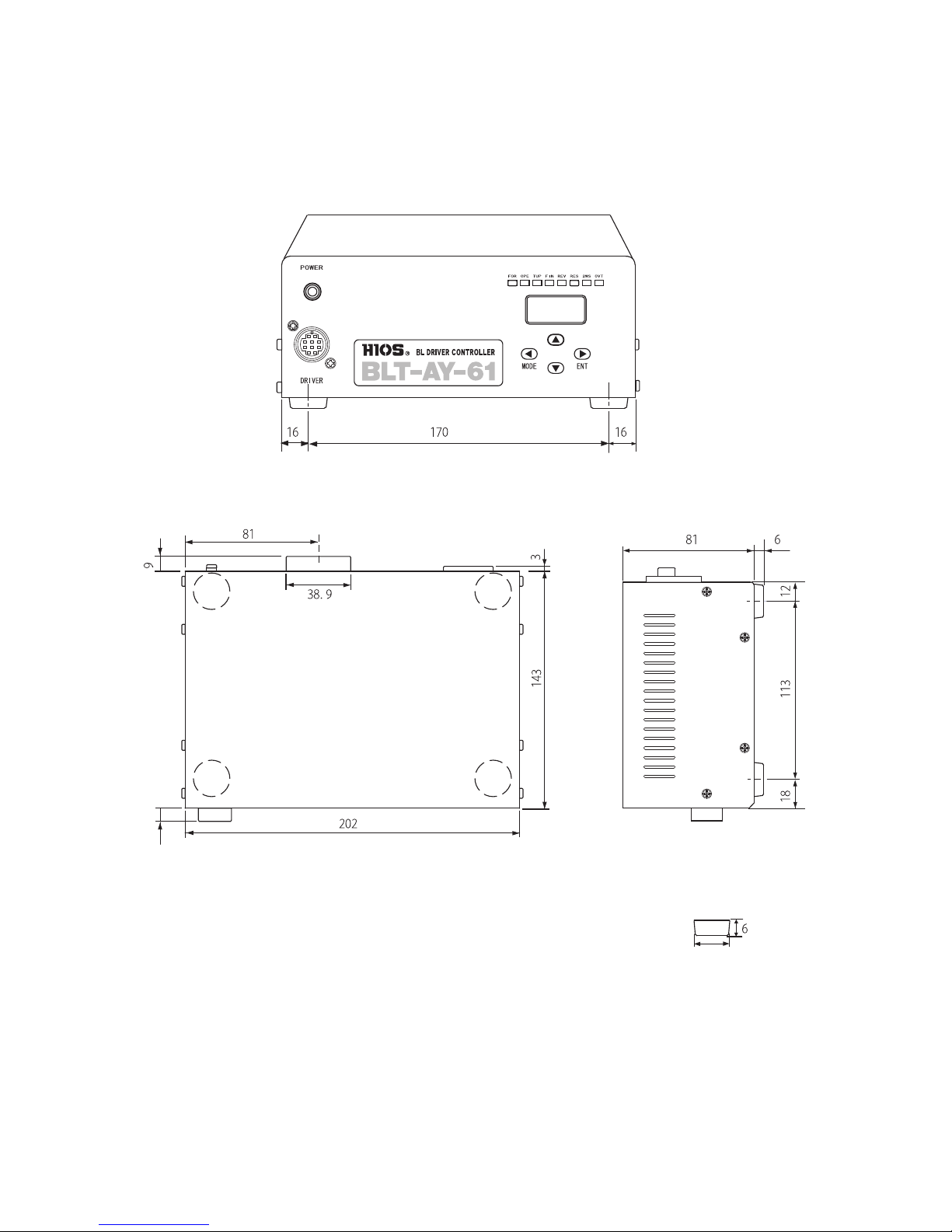
■ Exterior Drawings
BLT-AY-61 and BLT-AY-71 have common exterior drawings.
FrontFront
(Caution) The above exterior drawing of the power supply for brushless screwdrivers Not to
scale.
(Front View)
(Overhead View)
Input terminal block
(Right Side View)
Footing size 4-
∅
22
Unit: mm

- 8 -
■ Main Functions
1. The motor control circuitry is incorporated into the BLT-AY-61/ BLT-AY-71, giving the driver
a simpler construction.
2. The internal buzzer can be turned o (internal SW 6-1).
3. The FOR input for forward rotation from an external source can be switched between pulse
and reading (internal SW 6-2).
4. Forward / Reverse driver rotation High speed / low speed driver rotation can be controlled
externally.
5. The rpm can be set in 11 steps comprising 20 – 30 for high speed, and 11 steps comprising
5 – 15 for low speed.
6. The shape of the input signal can be selected to suit the movement of the cam during
torque up operations. Torque up can also be set for reverse rotation (for tightening counter
screws).
Eg 1: Set to U1 when tightening with high rpm and one impact (one UP trigger edge)
Eg 2: Set to d3 when tightening with low rpm and three impacts (three DOWN trigger)
7. If the driver keeps rotating and the overtime setting is set on the controller, the driver will
stop automatically and a buzzer will sound (recovery by turning power OFF / ON).
8. If the driver is overloaded, the overload protection circuit will be activated, the driver will
stop and a buzzer will sound (recovery by turning power OFF / ON).
9. Operation display indicators are installed on the front panel to monitor driver operation.
10. Simple settings are available with the combination of four buttons (Mode, ↓ , ↑ and ENT)
and the 2-digit seven segment display.
11. The internal power supply has a power selector switch and can be used with voltages of
any country.
12. The power unit has been made compact and lighter compared to other power units for automatic drivers.
13. The rear terminal block is removable, making installation and replacement simple.

- 9 -
■ Main Terminology
1. Tightening Check (setting the impact number)
To check that the screw has been tightened properly or to tighten the screw further, the
screw is tightened two or three times after the initial tightening. A tightening check can also
be referred to as a second tightening or re-tightening.
2. Torque Up
After the screw has been tightened and the tightening torque reaches the set torque, the
electric driver clutch disengages.
3. UP Trigger
Used when the clutch signal is received on the upslope of the cam when the bit is rotating at
high speed.
4. DOWN Trigger
Used when the clutch signal is received on the down slope of the cam when the bit is rotat-
ing at low speed.
5. Input Method
Signal input to the unit is through a photo coupler with a maximum current of 10 mA.
If an open collector connection is used, connect the emitter to GND and the input to the col-
lector.
(Caution)
Do not apply any voltage to the inputs. Install a diode that absorbs reverse voltages to the
relay coil on the input connections. If any auxiliary equipment is used, include electrical
noise suppression.
6. Output Method
The output signal of the unit is through a dry contact output internal common GND on one
side with a maximum rated load of DC 24 V / 500 mA. A common GND for connections with
auxiliary equipment should be used.
(Caution)
Do not apply voltage to the inputs. Install a diode that absorbs reverse voltages to the relay
coil on the input connections. If an auxiliary unit is used, carry out electrical noise suppression.
7. Overload Protection
The overload protection circuit stops output to protect the unit and electric driver from ex-
cess current if the driver is operated into overload.
The overload protection is activated, turn o the control unit and let it sit idle for at least one
minute. The driver may be operated after turning the unit back on.
(Caution)
Please note that if the driver is repeatedly overloaded, activating overload protection, the cur-
rent rating of the unit or the electric driver may be exceeded.
- 10 -
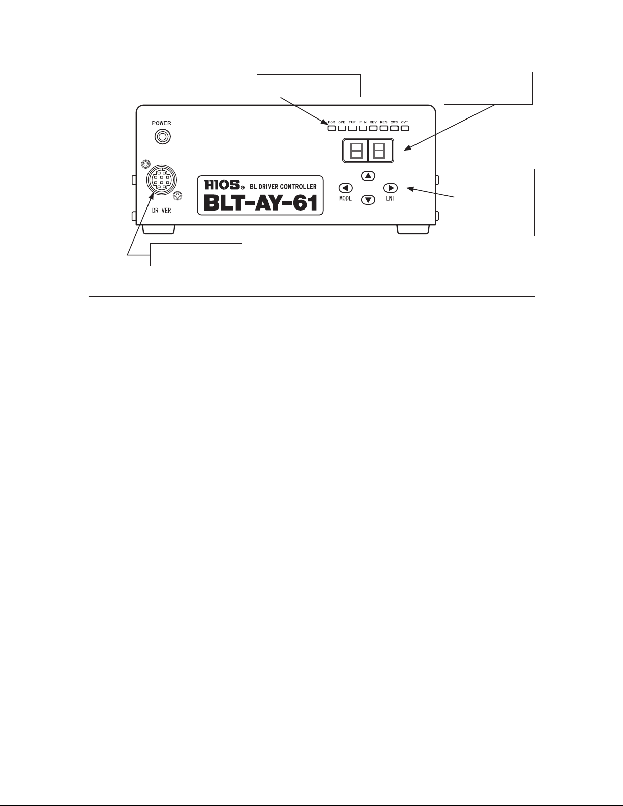
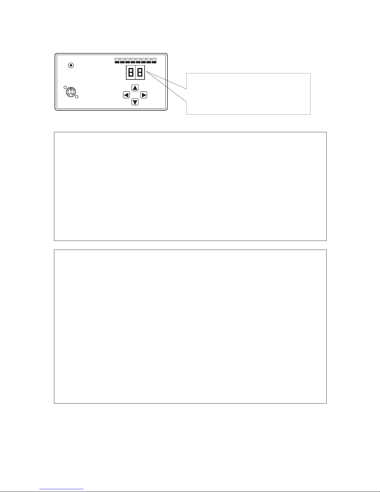
■ Front Panel
2. Driver Connector
5. Function Button
▲ UP Button
▼ DOWN Button
ENT Button
3. Operation Display LED
4. Setting Value
Segment Display
1. Main SW
A green LED will light up when the power is turned ON, and the operation display LEDs and
all segments of the value display will light up for 1 second.
2. Driver Connector
Attach the automatic BL driver cable.
3. Operation Display LEDs
The state of auxiliary inputs and outputs as well as the driver’s operation can be monitored
with this LED array.
4. Setting Value Segment Display
Displays the settings for torque up rpm for Forward driver rotation / torque up rpm for re-
verse rotation / 2WS HIGH side rpm / 2WS LOW side rpm / 2WS HIGH side overtime / 2WS
LOW side overtime.
5. Function Button / UP Button / DOWN Button / ENT Button
Driver operating settings should be changed after a reset signal has been input. Other
inputs such as 2WS should also be disabled so that there are no LEDs lit up. Pressing the
Function Button will result in a short beeping buzzer sound. Holding the button down longer will result in a short beeping buzzer sound, and the operation display LED and setting
value segment display will turn on. Pressing the ENT button will switch between the operation display LED and setting value segment. The UP/DOWN buttons are used to change the
value of the settings.
After the settings are complete and the Function Button is pressed again, a short beep
buzzer will sound. On holding the button down longer, a two-second beeping buzzer will
sound one second from the start of pressing the button and the setting value segment display will turn o, indicating that settings are complete.
● Refer to page * for more information on how to change each setting.
- 11 -
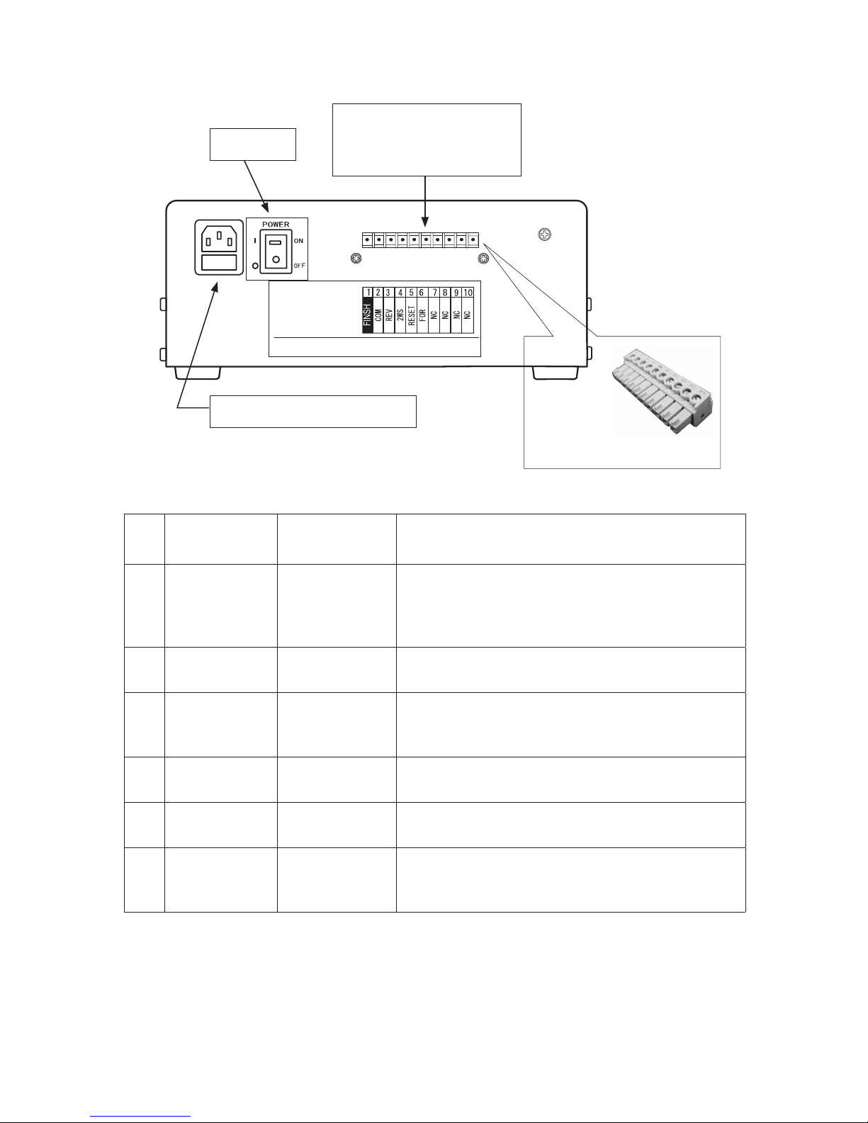
■ Rear Panel Input / Output
No
Input /
Output
Signal Name Outline
1 External Output FINISH Output
Output is present on this terminal when screw tightening is complete. Output ceases when either the
next FOR or REV input is received or when the RESET
input is used.
2 Common COM
Common for input and output. This is connected to
the internal controller GND.
3 External Input REV Input
Apply input to this terminal when you wish to operate
the driver in reverse rotation. The driver will operate
in reverse while the signal is present.
4 External Input 2WS Input
Driver rotation SPEED can switch between two stages.
2WS will be the LOW side while the signal is ON.
5 External Input RESET Input
Used when the driver operation is to be stopped by
an external source.
6 External Input FOR Input
Apply input to this terminal when you wish to operate the driver in forward rotation. The method can be
selected between pulse and reading. *
1
*1 When the input method is set to pulse, the driver will operate in forward rotation when a FOR input pulse of
100 ms or more is received.
To stop rotation, apply input to the RESET terminal.
The reading input for the start method means that the driver rotates FOR while FOR is input.
To stop the rotation, turn the FOR input OFF or use the RESET input.
Pulse or reading can be switched with the DIP SW on the internal board.
Inlet with Fuse Holder 3 A / 250 V
External I/O terminal
Terminal block connector
on the main body
Model number: XW4A-10B1-V1
Accessories:
Power supply side
Terminal block connector
1. Main SW
- 12 -
p.12
MODE
ENT
DRIV ER
POWE R
FOR OPE TUP FIN REV RES 2WS OVT
The BLT-AY-61 and BLT-AY-71 can be switched between 2WS HIGH (20 – 30) and 2WS LOW
(5 – 15) by turning 2WS ON / OFF. The bit can be rotated in reverse by turning REV (reverse
rotation input) ON / OFF.
The torque up number can be set regardless of whether the rotation is forward / reverse
or HIGH / LOW.
Change the number by following the steps in the MODE settings (pages 14 – 15).
In order to prevent the driver from rotating in the case of an accident, the built-in over-
time timer can also be set in the same way regardless of whether the rotation is forward /
reverse or HIGH / LOW.
Change the number by following the steps in the MODE settings (pages 14 – 15).
The factory settings are as follows.
● 2WS HIGH forward rotation impact number U1
● 2WS HIGH reverse rotation impact number U0
● 2WS HIGH setting speed 30
● 2WS HIGH overtime setting value t0 (approximately 42 minutes)
● 2WS LOW forward rotation impact number d1
● 2WS LOW reverse rotation impact number d0
● 2WS LOW setting speed 15
● 2WS LOW overtime setting value t0 (approximately 42 minutes)
● Overload protection function Front panel OL display
* For the impact number setting, if you set U0 or d0, torque up does not happen and the impact is contin-
ued (setting without torque up).
When the main SW is turned ON, the green
SW LED light up.
All operation LEDs and the setting value segment display will turn on for one second.
Display When the Power is ON with the Default Settings
(Note)
HIGH reverse rotation impact number or LOW reverse rotation impact number should be set at
U0 or d0 to use the driver for removing screws.
 Loading...