

HIOS BLG-IF1 Instruction Manual
ET-E011_BLG-IF1_17A
1/2
Instruction Manual
BLG serial-to-parallel Conversion Box BLG-IF1
■ Overview
The BLG-IF1 is a conversion box to convert the signal transmission of the BLG-BC2 driver from serial
communication to parallel communication.
With the BLG-IF1 the driver can be interlocked with external devices such as a PLC by using each of the input and
output signals in the “■ Details of the 26 pin connector” below.
By converting the signal transmission it is easy to design your product assembly lines.
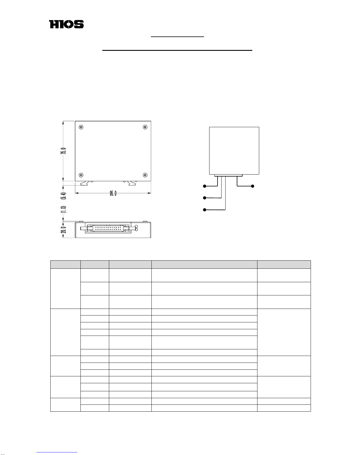
■ Dimensions and Specifications
■ Details of the 26 pin connector
(Note: Make sure not to operate the driver while inputting the following input signals from external devices.)
Pin No.
Signal Name
Details
Conditions
Input
1
Panel
Operation
To lock / unlock the Setting Buttons on the
driver (Tamper proof function)
ON →
the buttons get locked
2
Lever Operation
To turn on / off the driver
(The driver can be on as needed)
ON →
the driver is turned off
3
Work Sensor
To turn on / off the driver by judging
presence or absence of the work piece
ON →
the driver is turned on
Output
7
Start
Start signal
Open collector
up to 35V/100mA
8
T.UP
Finish signal (each clutch activation)
9
PASS
Pass signal (No errors)
10
Fail
Error signal (errors detected)
11
COMP
Completion signal (completion of preset
cycle count)
15
GND
GROUND
(RS-232C)
BLG
17
RXD
Connect to Terminal #3 of the D-SUB9P
D-SUB9P attached
18
TXD
Connect to Terminal #2 of the D-SUB9P
19
GND
Connect to Terminal #5 of the D-SUB9P
(RS-232C)
PC
20
GND
Connect to Terminal #5 of the D-SUB9P
Not attached
21
RXD
Connect to Terminal #2 of the D-SUB9P
22
TXD
Connect to Terminal #3 of the D-SUB9P
Input
power
25
+Vcc
8-28V
26
-Vcc
Common
IF-1
(RS-232C)
(RS-232C) PC
(OUT)
(IN)
ET-E011_BLG-IF1_17A
2/2
■ Accessories
Accessories
No. of pcs
Details
D-SUB 9 pin
Male connector
1
(Please connect it with the BLG-BC2 series)
* Note: To connect with the BLG-BC2
The BLG-BC2 I/O Cable “BLG-BC2-3010” needs to be purchased additionally.
26 pin cable
with a connector
1
(Please connect it with PLC)
* Note: To connect with a PC
A Commercial D-SUB 9 pin connector and a RS-232C cable (Straight cable) need
to be purchased additionally.
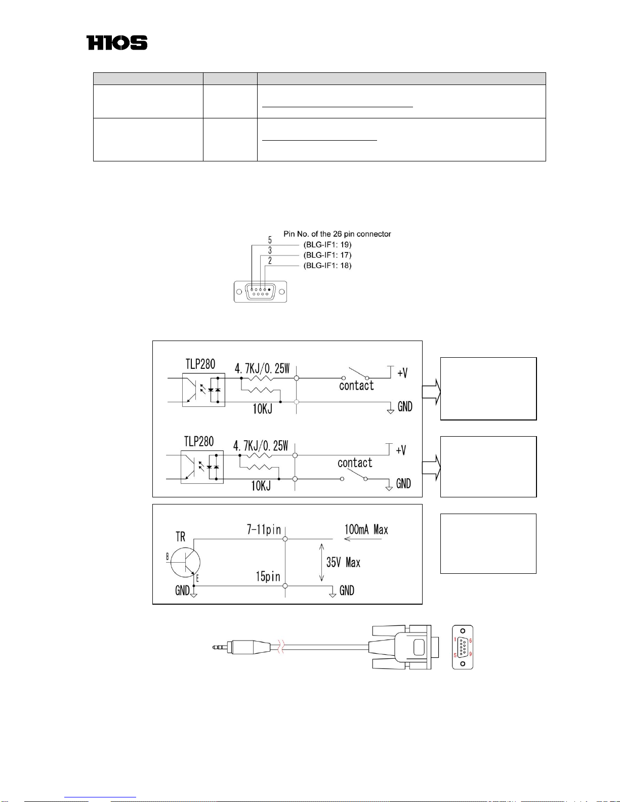
■ Wiring connection
1. To use the BLG-IF1 with the driver, the attached D-SUB 9 pin connector needs to be installed to the box to
connect with the driver. Adjust the length of the 26 pin cables and position of the D-SUB 9 pin connector based
on the use conditions, and connect the D-SUB 9 pin connector and the 26 pin connector.
2. To connect with external devices such as a PLC (In some usage conditions, also connect to the COM as needed
basis.)
* Option BLG-BC2 I/O Cable
BLG-BC2-3010
* Note: Make sure to turn on the power supply after doing all the necessary wiring connection to prevent malfunction,
and not to operate the driver while inputting the signals from external devices.
Connect COM (#5 or 6)
to GND.
To do this connection,
#26 needs to be used.
Input circuit (reference)
Output circuit
* #25 and 26 need to be
shared with the external
input power source to do
the connections above.
Connect COM to +V
(8-28V).
To do this connection,
#25 needs to be used.
Internal circuit
sink current
Internal circuit
Internal circuit
source current
Jackφ2.5
D-SUB 9 pin female
Length: 3m
 Loading...