

HIOS BLG-4000BC2, BLG-4000BC2-LT, BLG-5000BC2, BLG-5000BC2-15, BLG-5000BC2-18 Operation Manual
...
Built-in screwdriver & Pulse system
BLG-BC2 Series
BLG-4000BC2 / BLG-4000BC2-LT
BLG-5000BC2 / BLG-5000BC2-15 /BLG-5000BC2-18 / BLG-5000BC2-HT
BLG-7000BC2
Operation Manual
(2019.7)
ET-A011-BC2 19A

Table of Contents
03 Important Safety Instructions
05 Checking Supplied Accessories
06 Setting Up the Device
Connecting the Cord
Attaching a Bit
Changing the Start Mode (for BLG-5000BC2
Series /BLG-7000BC2)
BLG-5000BC2 Series
BLG-7000BC2
10 Parts and Their Functions
BLG-4000BC2 Series
BLG-5000BC2 Series
BLG-7000BC2
Operation Panel
13 Basic Operations
How to Change Rotation Speed
14 Setting the Torque
BLG-4000BC2 Series
Output Torque Guide (HI Input)
How to Change to Smaller Torque
BLG-5000BC2 Series /BLG-7000BC2
Output Torque Guide (HI Input)
17 Setting the Pass / Fail Criteria
Setting by Direct Teaching
Setting by Manual Procedure
20 Setting Screw Counter
22 Setting Menu List
How to Operate Setup Mode
<Counter>
<Screw Counter>
<Minimum Pulse>
<Maximum Pulse>
<Work Reset Timer>
<Count Timer for Reverse Rotation>
02
<System>
<Pulse Detection>
<Total Torque-ups (count)>
<Inactive Time of Torque-up>
26 Connecting the Special Cable (Option)
Checking Supplied the Cable Accessories
BLG-BC2-3010 (BLG-4000BC2/BLG5000BC2 Series)
BLG-BC2-3012 (for BLG-4000BC2-LT /
BLG-7000BC2)
Connecting to Screwdriver (BLG-4000BC2/
BLG-5000BC2 Series)
Connecting to Screwdriver (BLG-7000BC2)
31 Saving Screw Fastening Data
System Requirements
Screen of Connection
Connecting to Screwdriver
Sending Command
Work Monitor
Screen of Administration
Specications of Communication by Special
Cable
Message Format
Communication Command / List of
Messages
43 Troubleshooting
Common Problems
When the Messages Below Are Displayed
Want to See the Device Version
45 Maintenance
46 Specications
BLG-4000BC2 Series
BLG-5000BC2Series
BLG-7000BC2
49 Notice

Important Safety Instructions
Please read this manual and the power supply unit manual carefully before use to ensure proper operation. In
addition, do not use the product in the way not described in this manual. Please note that we are not
responsible for any problems caused by using the product in a manner that does not conform to the contents
of this manual, using it improperly, or repairing / modifying by a third party except by us or someone specied
by us.
Installation
Do not install the device at the places described
◦
below. Otherwise, it may cause a re or a failure.
A place of high humidity or with a lot of dust
・
A place where it becomes high temperatures
・
A place of re
・
A place of direct sunshine
・
A place c ontaining corrosive gas in the air
・
Unstable place
・
Do not use the device where the ambient
◦
temperatures are out of the range of 5 to 40 °C.
Power Supply
Be sure to install an earth leakage break er and a
◦
safety breaker on the commercial power source
before using it.
Connect the earth wire to the earth wire terminal
◦
of the outlet. You may have an electric shock
without the earth wire connection in case of an
electric leakage.
Avoid the octopus foot wiring and use of an
◦
extension cord. Otherwise, it may cause a re or an
electric shock.
Do not connect anything other than specied to
◦
the connection part of this device. Otherwise, it
may cause an electric shock or a failure.
Handling
Do not wear clothes with ippers on the cus,
◦
gloves, neckties etc. Otherwise, they may get
caught in the rotating screwdriver and cause an
injury or a failure.
Wear suitable clothing and protective eye-wear for
◦
work. Cover long hair with a hat etc. so that you
can work safely.
Turn o power when you leave the workplace, or
◦
when you attach / remove a bit / an optional item.
If static electricity is charged, you need to
◦
neutralize it before use.
Avoid an unstable place or an unreasonable
◦
posture for work. Otherwise, it may cause an
injury.
Long-time work or some types of work may cause
◦
strain on your hands, neck, arms or waist, causing
an injury. Avoid long-time work and take a break
regularly.
We recommend use of a balancer to prevent the
◦
device from falling and to protect cords / wires.
Hold the plug when you attach / remove the
◦
power cord, screwdriver and so on.
Protect cords / wires by not giving damages to
◦
them; not remodeling them; not pulling them; not
bending them forcibly; etc. Also, do not place
heavy items on the power cord. Otherwise, it may
cause a re or an electric shock.
If you detect an uneven rotation, strange noises,
◦
overheating or activation of a breaker, etc., stop
using the device immediately and have it repaired.
03

However, note that the device may be overheated
depending on the frequency of the workpiece or
screw types. As a countermeasure, prepare spare
screwdrivers of the same model to extend the tact
time and use them alternately, or review the
selection of screwdriver models.
Do not overload the device so much that it cannot
◦
clutch. Otherwise, it may cause a failure of the
motor.
Do not touch the screwdriver while it is rotating.
◦
Otherwise, it may cause an injury or a failure.
Keep your hands and face away from the rotating
◦
section while in use. Otherwise, it may cause an
injury.
Remove the bit from the screwdriver when you are
◦
not working.
If you cannot attach / remove the bit in the way
◦
described in this document, please make contact
with our service section.
Fix the workpiece with jig / clump while in
◦
working.
Do not use the switch lever as a hanger. Otherwise,
◦
it may cause an accident or an injury.
Do not give a strong impact or excessive force.
◦
Otherwise, it may cause a failure.
Do not operate the screwdriver with wet or oiled
◦
hands.
Do not operate the FOR / REV switch before the
◦
screwdriver completely stops. Otherwise, it may
cause a failure.
Do not disassemble / remodel this device.
◦
Otherwise, it may cause a failure.
Maintenance and Inspections
Turn o power and remove the power plug from
◦
the outlet when the device is not in use for a long
time.
Remove the accessories from the screwdriver and
◦
store them in the package box when it is not in use
them for a long time.
Inspect the device regularly to conrm there are
◦
no damages. If you use it with damages, it may
cause a re or an electric shock.
When you clean the device, turn o the power and
◦
remove the power plug from the outlet.
Otherwise, it may cause a re or an electric shock.
Use dry cloth to wipe of dust or stains. The dust
◦
may absorb moisture to allow current to ow,
causing a re.
Store the device in a place where the appropriate
◦
temperatures and humidity are controlled.
Do not store the device in an unstable place or a
◦
place with vibrations. Otherwise, it may cause a
failure.
Keep the device out of reach of anyone but people
◦
involved in the workpiece.
We recommend genuine HIOS parts for
◦
replacement.
04
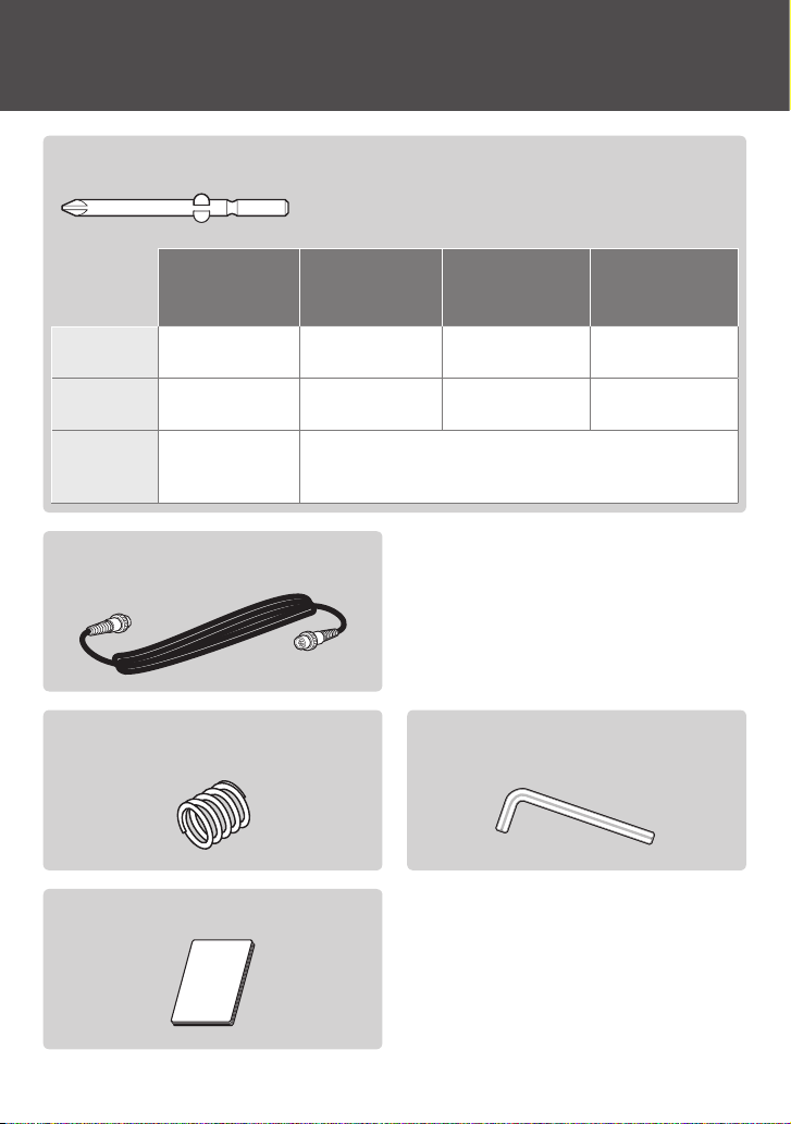
Checking Supplied Accessories
One bit for each socket
BLG-4000BC2-LT BLG-4000BC2
Bit Drive
H4
Bit Drive
H5
Bit Drive
1/4 HEX
+#0 (Ø2.0×40mm)
+#0 (Ø2.5×40mm)
– –
–
+#0 (Ø2.5×40mm)
+#1 (Ø4.0×40mm)
Screwdriver cord: 2 m (6P)
Adjustment spring for low torque
(BLG-4000BC2/BLG-4000BC2-LT Only)
BLG-5000BC2
BLG-5000BC2-15
+#1 (Ø4.0×40mm)
+#2 (Ø4.0×40mm)
+#1 (Ø5.0×60mm)
+#2 (Ø5.0×60mm)
+#1 (Ø5.0×50mm)
+#2 (Ø5.0×50mm)
– (Ø5.0×50mm)
BLG-5000BC2-18
BLG-5000BC2-HT
BLG-7000BC2
–
+#1 (Ø5.0×60mm)
+#2 (Ø5.0×60mm)
Hexagon L-shaped wrench: 5 mm across ats
(BLG-5000BC2 Series/BLG-7000BC2 Only)
Instruction manual
05
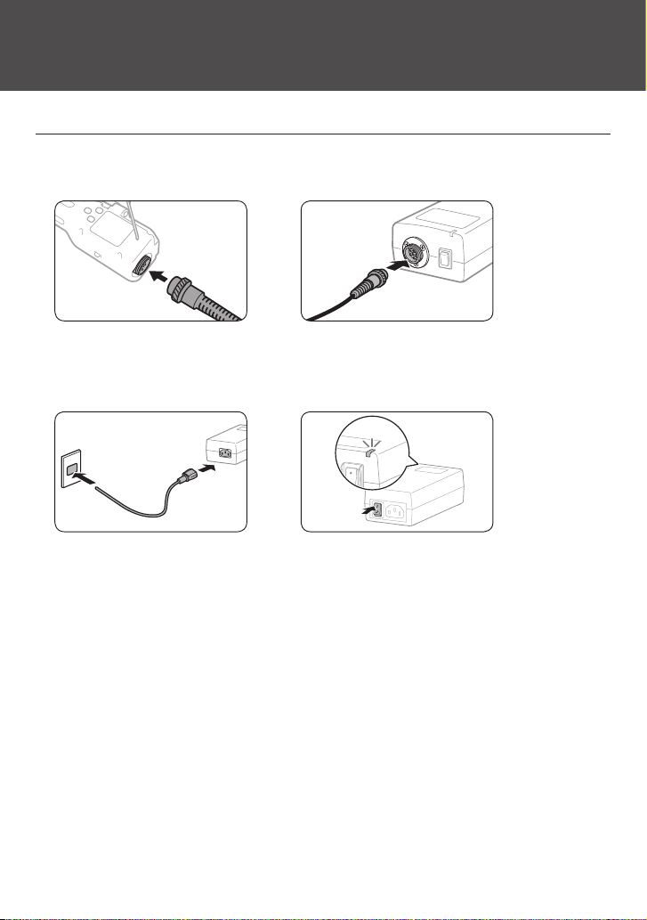
Setting Up the Device
Connecting the Cord
Connect the screwdriver cord to the power unit and the screwdriver.
1
Use the joint ring for xing to prevent the cord from coming o.
◦
▶
Connect the power unit cord to the power unit and the outlet and turn
2
on the switch.
The indicator on the power unit turns on.
◦
▶
06
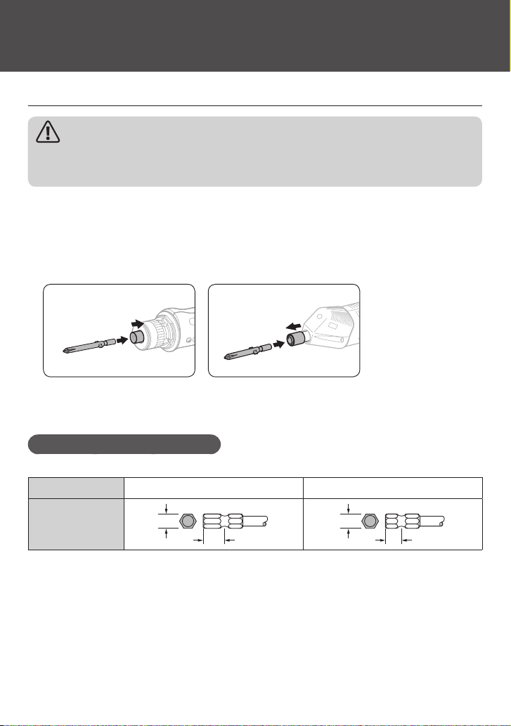
Attaching a Bit
Caution
Do not attach / remove the bit while power is on. Otherwise, it may cause an unexpected
accident.
Insert the bit into the joint shaft collar.
1
BLG-4000BC2 / BLG-4000BC2-LT: Attach the bit while pushing the joint shaft collar into the
◦
screwdriver.
BLG-5000BC2 Series / BLG-7000BC2: Attach the bit while pulling out the joint shaft collar from the
◦
screwdriver.
BLG-4000BC2/BLG-4000BC2-LT
BLG-5000BC2/BLG-7000BC2
Conrm the bit has been attached rmly by pulling it light.
2
Precaution for Use of Hexagonal Bit
You cannot use a double head bit with double grooves. Prepare suitable sockets for those bits.
Bit Socket 5HEX (5 mm across ats) 1/4HEX (6.35 mm across ats)
Type
5
14.0
6.35
9.0
07
Changing the Start Mode (for BLG-5000BC2 Series /BLG-7000BC2)
You can change the mode to push start for BLG-5000BC2 Series and BLG-7000BC2. In the push
start mode, the screwdriver starts rotation when you press it into an object.
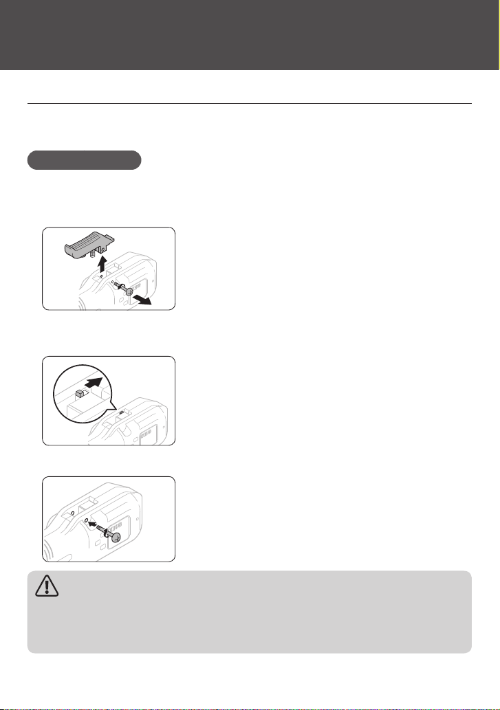
BLG-5000BC2 Series
Remove the switch lever.
1
Remove the shaft screw.
◦
Be careful not to lose the lever spring.
◦
Change the start mode.
2
Use something pointy such as a pen.
◦
Re-attach the shaft screw.
3
Caution
Do not give a strong impact to the start mode switch. Otherwise, it may cause a failure.
◦
Do not use the screwdriver while the shaft screw is not fixed. Otherwise, it may cause a
◦
failure.
08
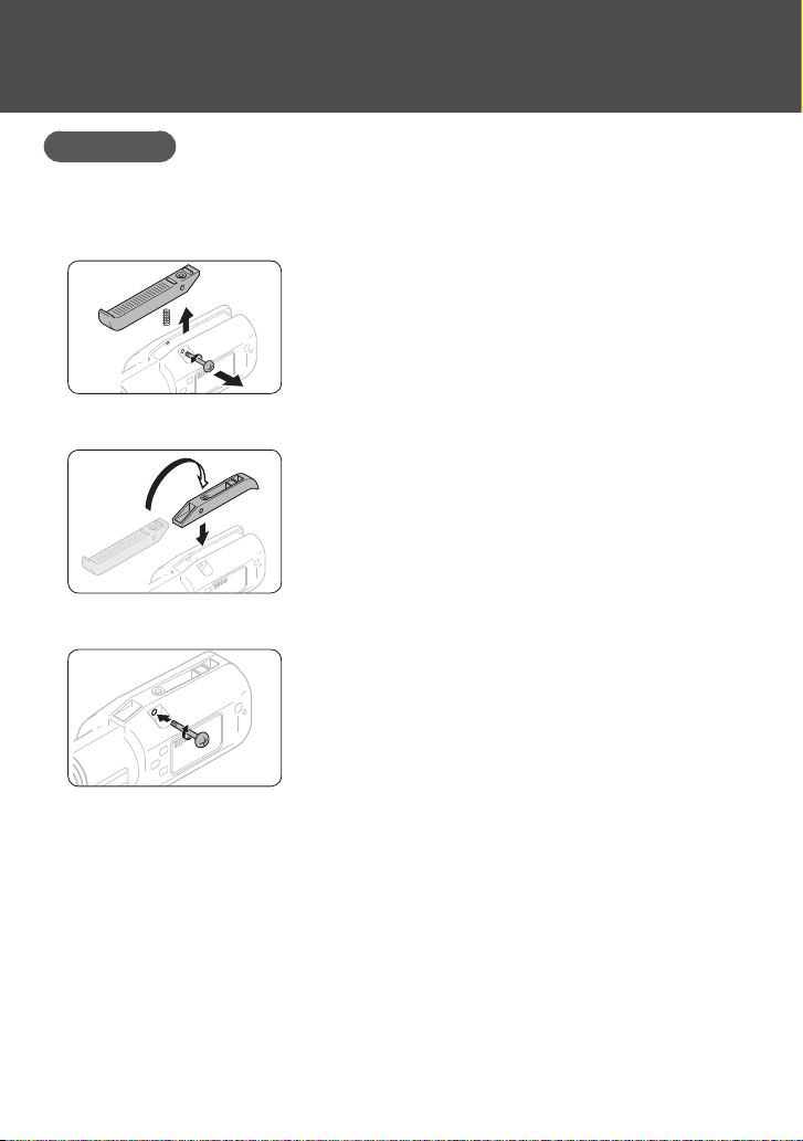
BLG-7000BC2
Remove the switch lever.
1
Remove the shaft screw.
◦
Be careful not to lose the lever spring.
◦
Turn over the switch lever and attach it.
2
Re-attach the shaft screw.
3
09

REV
0
FOR
864
2
REV
0
FOR
REV
0
FOR
Parts and Their Functions
BLG-4000BC2 Series
❶ ❷ ❸ ❹ ❺❻ ❼
❽❾❿⓫
BLG-5000BC2 Series
❶ ❸ ❹ ❺❻ ❼
1
5
3
7
BC2
COUNT CONTROL
PASSFail M
COUNT CONTROL
Fail PASS M
BC2
BLG-7000BC2
10
❶ ❸
1
5
9
3
7
❽⓬❿ ❾
❺❻ ❼
BC2
COUNT CONTROL
Fail PASS M
❽❿ ❾
❹

Joint shaft collar
❶
This is to be used to attach the bit or remove it.
Protection cover of torque adjustment nut
❷
This can be removed by turning it counterclockwise.
Switch lever
❸
This is used to start the screwdriver.
For 7000BC2, if you attach the lever upside down, you can use the push start.
External I/O port
❹
Send / receive the data via this port with the special cable (option). You can change the set values of
the screwdriver from an external device (e.g. PC, PLC, etc.) and send out screw fastening data.
Joint ring
❺
This is to prevent the screwdriver cord from coming off unexpectedly.
Screwdriver cord
❻
This is to connect the screwdriver to the power unit. The plug on one end is the same as that on the
other end.
Hanger
❼
This is used to hang the screwdriver from the balancer.
FOR/REV switch
❽
You can change the rotational direction with this switch.
FOR: Clockwise
◦
0: Neutral
◦
REV: Counterclockwise
◦
Adjustment scale of torque
❾
This is used as a guide for output torque adjustment. For details, refer to“Setting the Torque” (P. 14).
Torque adjustment nut
❿
This is used for output torque adjustment.
Nut fixing ring (BLG-4000BC2-LT Only)
⓫
This prevents the torque adjustment nut from moving improperly. Fit it closely with the torque
adjustment nut.
Start mode change switch
⓬
This is used to change the start mode.
L: Lever start
◦
P: Push start
◦
For details, refer to “Changing the Start Mode (for BLG-5000BC2 Series /BLG-7000BC2)” (P. 08).
11
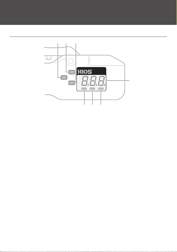
Operation Panel
❶ ❷ ❸
BC2
COUNT CONTROL
❹
PASSFail M
❺❻❼
F1 button
❶
This is used to change the mode to setting or change the setting items.
F2 button
❷
This is used to change the mode to direct teaching or change the digit of the setting.
F3 button
❸
This is used to change the setting.
Display
❹
This displays the number of pulses, the operational conditions of the screw counter, error conditions
and etc. In addition, you follow the instructions on the display during setup.
M indicator
❺
This turns on when operations on the button are inactive. In addition, it blinks in the mode of
temporary fastening (option).
PASS indicator
❻
This turns on when the result of fastening a screw is accepted.
Fail indicator
❼
This turns on when the result of fastening a screw is not accepted.
12
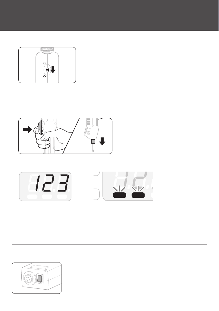
Basic Operations
M
Set the FOR / REV switch to <FOR>.
1
REV
0
FOR
When you change the rotational direction, turn the switch to 0 to stop the screwdriver.
◦
Start the screwdriver.
2
In the lever mode, pull the switch lever for start.
◦
In the push mode, push the screwdriver in the direction of the bit.
◦
When the screwdriver starts, the pulse is counted, and PASS / Fail is indicated by the sound and
◦
the indicator.
▶
PASSFail M
In case of over 1000 pulses, <–––> is displayed. For details of how to set pass / fail, refer to “Setting
◦
the Pass / Fail Criteria” (P. 17).
When a screw is seated, the clutch is activated to stop rotation.
◦
If you restart the screwdriver, the PASS / Fail indicator turns o.
◦
PASSFail
How to Change Rotation Speed
When you want to change the rotation speed, use the switch for voltage output setting on the
power unit.
2: HI (30V)
◦
1: LOW (20V)
◦
13
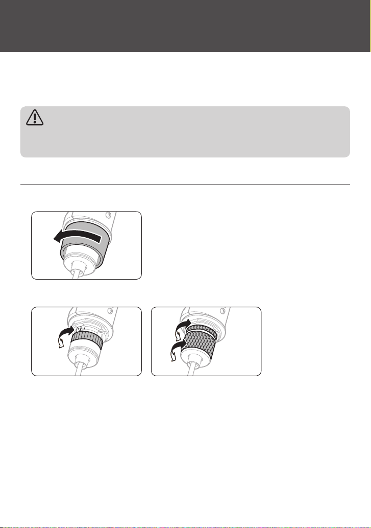
Setting the Torque
The torque can be adjusted by pushing the torque adjustment spring with pressure. If you turn
the torque adjustment nut clockwise, the torque becomes large, and you turn it
counterclockwise, it becomes small.
Caution
“Output Torque Guide” and the torque adjustment scale should be considered as a guide; they
do not guarantee actual torques. Use the torque meter by HIOS to check the torque precisely.
BLG-4000BC2 Series
Remove the protection cover of the torque adjustment nut.
1
Turn the torque adjustment nut to set the fastening torque.
2
4000BC2-LT4000BC2
Adjust the edge face of the torque adjustment nut to come right above the scale.
◦
For BLG-4000BC2-LT, adjust the edge face of the nut xing ring to come right above the scale.
◦
When the nut xing ring’s position is determined, align the torque adjustment nut just to t to the
ring.
Re-attach the protection cover of torque adjustment nut.
3
14
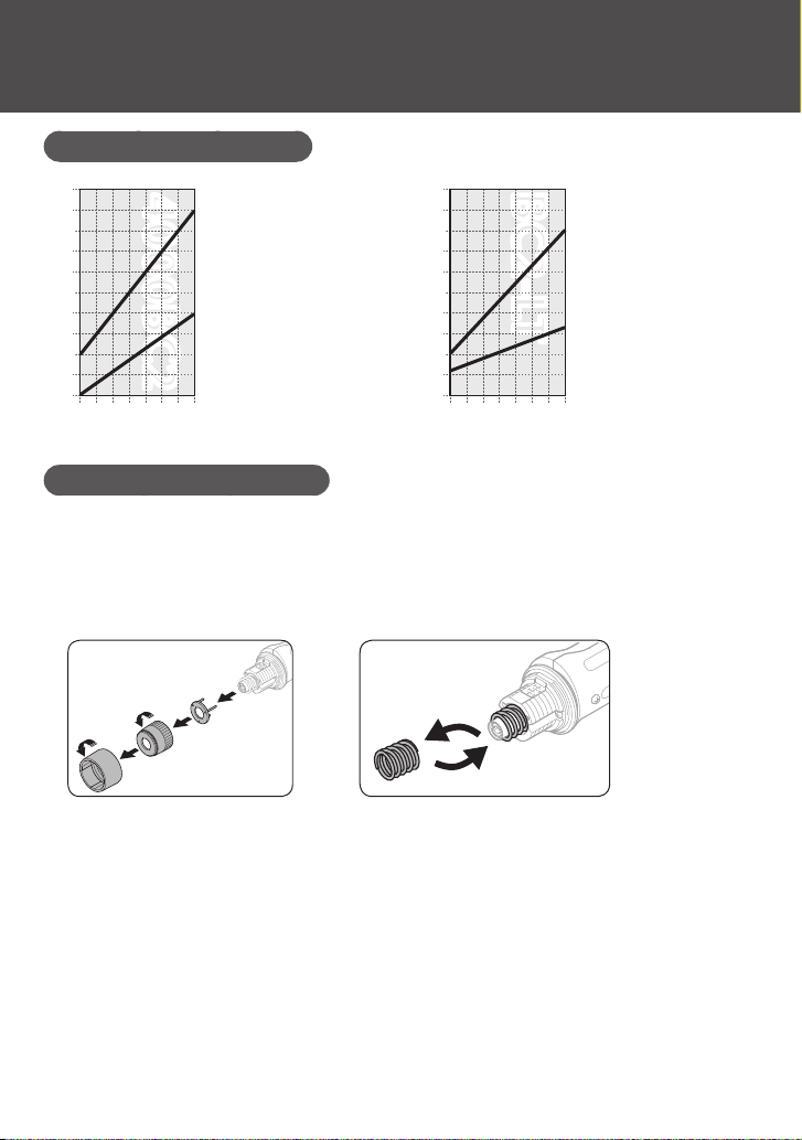
Output Torque Guide (HI Input)
N·m
0.6
0.5
4000BC24000BC2
Spring on the device
0.20
N·m
BC2-LTBC2-LT
Spring on the device
0.4
0.3
0.2
0.1
1
2 3 4 5 6 7 8
Torquescale
How to Change to Smaller Torque
If you use the torque adjustment spring in the accessories, you can change the torque value
smaller. Change the spring depending on the work conditions.
Remove the torque adjustment nut and the spring holder and replace
1
Spring in the accessories
0.15
0.10
0.05
0.03
1
2 3 4 5 6 7 8
Torquescale
Spring in the accessories
the torque adjustment spring.
▶
Re-attach the torque adjustment nut and the spring holder.
2
Attach the spring holder along the notch.
◦
15
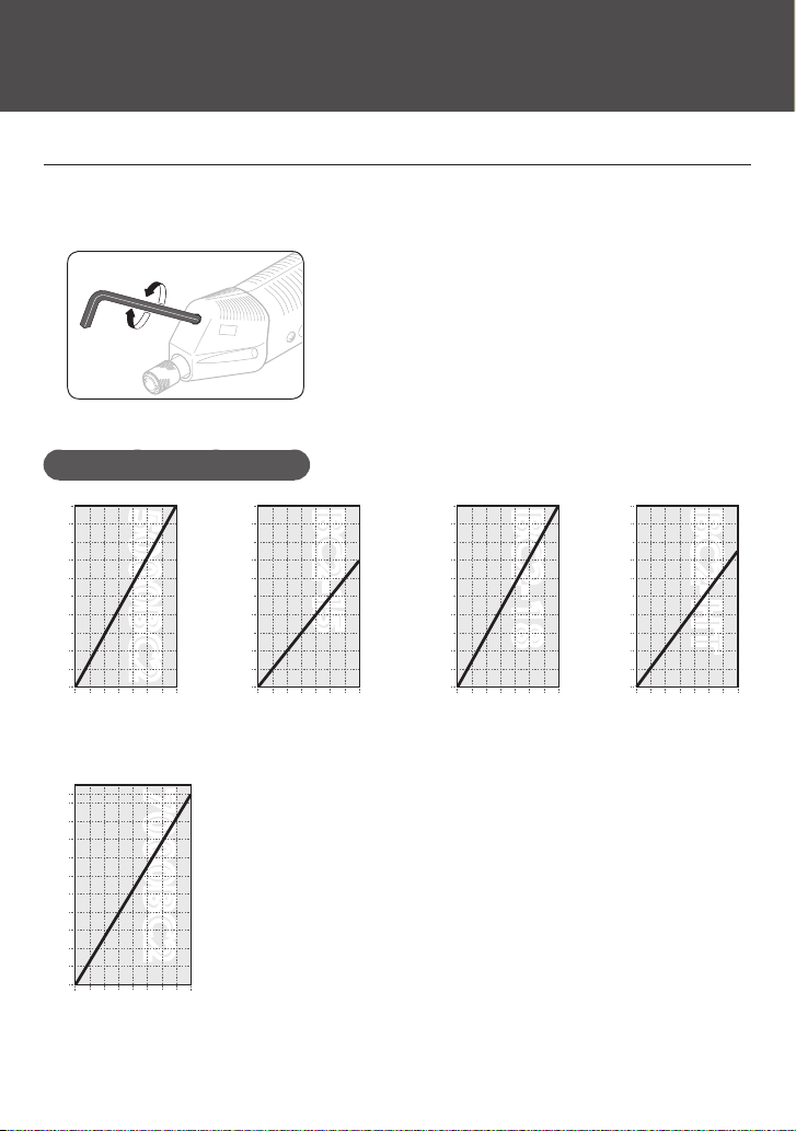
BLG-5000BC2 Series /BLG-7000BC2
Use the hexagon L-shaped wrench in the accessories to turn the torque
1
adjustment nut for setting the fastening torque.
Adjust the edge face of the torque adjustment nut to align with the scale.
◦
Output Torque Guide (HI Input)
N·m N·m N·m N·m
1.2
1.0
0.8
0.6
0.4
0.2
5000BC25000BC2
2 3 4 5 6 7 8
1
Torquescale
1.0
0.8
0.6
0.4
0.3
BC2-15BC2-15
2 3 4 5 6 7 8
1
Torquescale
1.5
1.3
1.1
0.9
0.7
0.5
2 3 4 5 6 7 8
1
BC2-18BC2-18
Torquescale
2.0
1.9
1.7
1.5
1.3
1.1
0.9
0.7
0.5
2 3 4 5 6 7 8
1
BC2-HTBC2-HT
Torquescale
N·m
2.8
2.7
2.3
1.9
1.5
1.1
0.7
2 3 4 5 6 7 8 9 10
Torquescale
16
7000BC27000BC2
 Loading...