

Z3003
マルチプレクサユニット
MULTIPLEXER UNIT
取扱説明書 / Instruction Manual
Dec. 2018 Revised edition 2
Z3003A980-02 18-12H
JA/EN
点検・保守
点検
本器がお手元に届きましたら、輸送中において異常または破損がないか点検し
てからご使用ください。万一、破損あるいは仕様どおり動作しない場合は、お
買上店(代理店)か最寄りの営業所にご連絡ください。
使用前の確認
使用前には、保存や輸送による故障がないか、点検と動作確認をしてから使用
してください。故障を確認した場合は、お買上店(代理店)か最寄りの営業所
にご連絡ください。
保守・サ-ビス
• 回路基板には触れないでください。端子部分の汚れをとるときは、柔らかい
布に水か中性洗剤を少量含ませて、軽く拭いてください。ベンジン、アル
コール、アセトン、エーテル、ケトン、シンナー、ガソリン系を含む洗剤は
絶対に使用しないでください。変形、変色することがあります。
• 故障と思われるときは、お買上店(代理店)か最寄りの営業所にご連絡くだ
さい。修理に出される際は、輸送中に破損しないように梱包し、故障内容も
書き添えてください。輸送中の破損については保証しかねます。
• 本器の確度維持あるいは確認には、定期的な校正が必要です。
安全について
この取扱説明書には本器を安全に操作し、安全な状態に保つのに要する情報や
注意事項が記載されています。本器を使用する前に次の安全に関する事項をよ
くお読みください。
この機器は IEC 61010 安全規格に従って、設計され、試験し、安
全な状態で出荷されています。測定方法を間違えると人身事故や機
器の故障につながる可能性があります。また、本器をこの取扱説明
書の記載以外の方法で使用した場合は、本器が備えている安全確保
のための機能が損なわれる可能性があります。取扱説明書を熟読し、
十分に内容を理解してから操作してください。万一事故があっても、
弊社製品が原因である場合以外は責任を負いかねます。
取扱説明書の注意事項には、重要度に応じて次の表記がされています。
操作や取り扱いを誤ると、使用者が死亡または重傷につながる危険性が極
めて高いことを意味します。
操作や取り扱いを誤ると、使用者が死亡または重傷につながる可能性があ
ることを意味します。
操作や取り扱いを誤ると、使用者が傷害を負う場合、または機器を損傷す
る可能性があることを意味します。
製品性能および操作上でのアドバイスを意味します。
規格に関する記号
測定可能範囲
測定電流
測定周波数 外部接続機器 : DC、10 Hz ~ 1 kHz
接点仕様
接点形式 メカニカルリレー
最大許容電圧 実効値 30 V およびピーク値 42.4 V、または直流 60 V
最大許容電力 30 W (DC)(抵抗負荷)
接点寿命 4 線式の場合 : 5,000 万回、2 線式の場合 : 500 万回(参考値)
確度保証条件
ウォームアップ時間 Z3003 を搭載する機器と同様
確度保証温湿度範囲 23 ℃ ±5 ℃、80%rh 以下
確度保証期間 1 年間
確度仕様条件 2 線式の場合、ゼロアジャスト実施後のみ確度保証とする
温度係数
追加確度(本体の測定確度に下記誤差を追加する)
リーク電流の影響
測定スピードの影響
オフセット電圧の影響
オフセット抵抗変動の影響2 線式の場合、下記抵抗を誤差に加算
内部のオフセット抵抗
内部測定経路の抵抗値 0.5 Ω(初期値)
環境・安全仕様
使用場所 屋内使用、汚染度 2、高度 2,000 m まで
保存温湿度範囲 -10 ℃~ 50 ℃、80%rh 以下(結露しないこと)
使用温湿度範囲 0 ℃~ 40 ℃、80%rh 以下(結露しないこと)
外形寸法 約 92W × 24.5H × 182D mm ( 突起物含まず )
質量 約 180 g
製品保証期間
付属品
取扱説明書 1 部
D-SUB
50 ピンコネクタ
f.s. : 最大表示値または目盛長 ( 一般的には、現在使用中のレンジを表します )
rdg. : 読み値(現在測定中の値、測定器が現在指示している値を表します)
Z3003 を搭載する機器 : DC1 A 以下
外部接続機器 : DC1 A 以下、AC100 mA 以下
0 ℃~ 18 ℃、28 ℃~ 40 ℃では
温度係数 ± ( 追加確度の 1/10)/ ℃を加算
測定電流に応じて、下記 rdg. 誤差を加算(ガードありにて)
(湿度 70%rh 未満。70%rh 以上の場合は下記 rdg. 誤差× 5 を加
算)
1 × 10⁻⁹ [A]
I
MEAS
: 測定電流
I
MEAS
積分時間が電源周期の整数倍でない場合、下記 f.s. 誤差を加算
A
× 0.5 [%f.s.]
fs
: Z3003 を搭載する機器の f.s. 誤差
A
fs
OVC OFF の場合に、下記抵抗を誤差に加算
10 × 10-6 [V]
I
MEAS
0.1 [Ω]
3年間
リレー接点は保証対象外
1 個(ピンヘッダ、ソルダカップ)
[A]
[A]
× 100 [%rdg.]
[Ω]
I
MEAS
: 測定電流
• 本器は防滴構造となっていません。コネクタ部に水滴が付着する
と、故障の原因になりますので、注意してください。
• 不安定な台の上や傾いた場所に置かないでください。落ちたり、
倒れたりした場合、けがや本器の故障の原因になります。
• 本器の損傷を防ぐため、運搬および取り扱いの際は振動、衝撃を
避けてください。特に、落下などによる衝撃に注意してください。
• ユニットを差し込むときは、板金部分を持って差し込んでくださ
い。基板を手で直接触ると静電気の影響で故障したり高抵抗レン
ジで確度不良の原因になる恐れがあります。帯電防止手袋を使用
すると共に静電気対策(静電気対策用リストストラップなどを使
用)をすることを推奨します。
• 本器を使用しないときは故障を防ぐため、お届けしたときの梱包
材料を使用し保管してださい。
Z3003 を搭載する機器の取り扱いについては、搭載する機器の取扱説明書をご
覧ください。
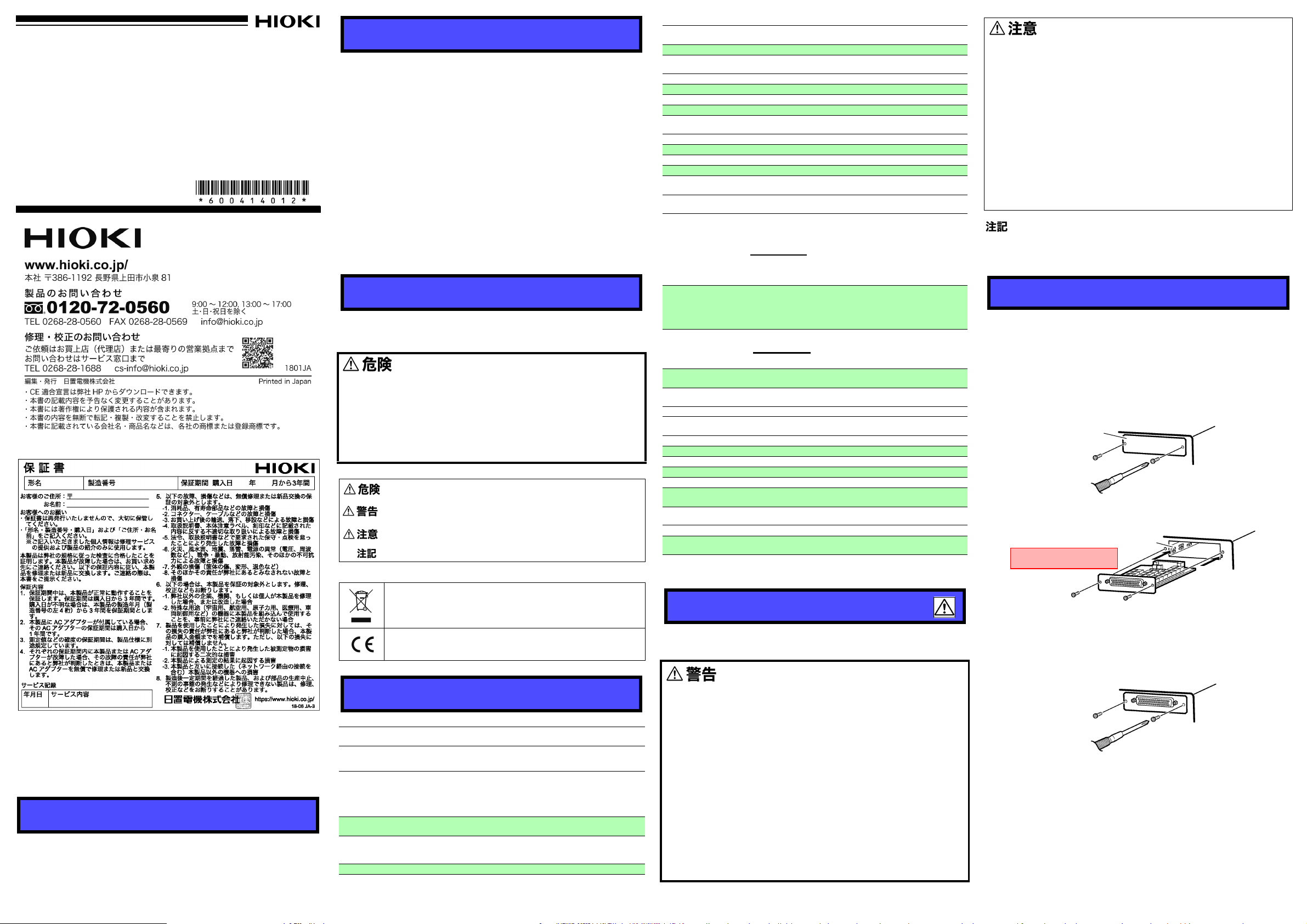
取り付け・取り外し
マルチプレクサユニットを取り付ける
用意するもの : プラスドライバ
1 搭載する機器の主電源スイッチを切り、コード・リード線類を外
します。
2 2 つの固定ネジをプラスドライバで外し、ブランクパネルを外し
ます。
搭載する機器の背面
ブランクパネル
3 マルチプレクサユニットの向きに注意して、奥までしっかりと差
し込みます。ガイドレールに沿わせて差し込んでください。
ガイドレール
基板に手で直接触れない
はじめに
このたびは、HIOKI Z3003 マルチプレクサユニットをご選定いただき、誠に
ありがとうございます。この製品を十分にご活用いただき、末長くご使用いた
だくためにも、取扱説明書はていねいに扱い、いつもお手元に置いてご使用く
ださい。
概要
Z3003 マルチプレクサユニットは測定端子を自由に組み合わせて多点測定で
きるユニットです。Z3003 対応の機器に組み込こむことで、多様な用途で使
用することが可能です。
EU加盟国における、電子電気機器の廃棄にかかわる法規制(WEEE
指令 ) のマークです。
欧州共同体閣僚理事会指令 (EC 指令 ) が示す規制に適合している
ことを示します。
仕様
測定対象(結線順は任意に選択可能)
4線式
2線式
マルチプレクサ入出力(電流印加方向は固定)
測定端子
(4 線式)
測定端子
(2 線式)
シールド端子
使用コネクタ D-SUB 50pin レセプタクル
10 か所(Z3003 2 ユニット使用時は 20 か所)
21 か所(Z3003 2 ユニット使用時は 42 か所)
TERM A1 端子~ TERM A10 端子、TERM B1 端子~ TERM B10 端子
(TERM 端子は次の端子の組み合わせ
SOURCE 端子 : 電流発生端子、SENSE 端子 : 電圧検出端子)
EX SOURCE A、EX SOURCE B : 外部機器接続端子(電流側)
EX SENSE A、EX SENSE B : 外部機器接続端子(電圧側)
TERM A1 端子~ TERM A21 端子、TERM B1 端子~ TERM B21 端子
EX A、EX B : 外部機器接続端子
GUARD 端子 : ガード端子
EARTH 端子 : 機能接地端子
EX GUARD : 外部機器ガード端子
ご使用にあたっての注意
本器を安全にご使用いただくために、また機能を十二分にご活用いただくため
に、次の注意事項をお守りください。
• 感電事故を避けるためマルチプレクサユニットは、搭載する機器
の主電源スイッチを切り、測定リード、すべてのコネクタ、電源
コードを外してから、取り付けまたは取り外しをしてください。
• ネジ留めを確実にしないと、仕様を満足しなかったり、故障の原
因になります。
• コネクタを確実に接続しないと仕様を満足しなかったり、故障の
原因になります。
• 起電力を持った測定対象 ( バッテリ、電源 ) を接続する場合には、短
絡保護をしてください。
• 本器の接点最大許容電圧は、実効値 33 V およびピーク値 46.7 V、
または直流 70 V です。耐圧試験器や絶縁抵抗計を直接接続しな
いでください。
• 感電事故を避けるため、搭載する機器はマルチプレクサユニット
を抜いたままで使用しないでください。マルチプレクサユニット
を抜いておくときは、ブランクパネルを装着してください。
Z3003 マルチプレクサユニット
ユニットを差し込むときは、帯電防止手袋を使用すると共に静電
気対策(静電気対策用リストストラップなどを使用)をすること
を推奨します。
4 マルチプレクサユニットの 2 つの固定ネジをプラスドライバで
しっかりと締めます。
設定については Z3003 を搭載する機器の取扱説明書をご覧くだ
さい。
マルチプレクサユニットを取り外す
搭載する機器の主電源スイッチを切り、コード・リード線類を外して
から、上記の逆の手順でマルチプレクサユニットを取り外し、ブラン
クパネルを取り付けます。
Z3003
MULTIPLEXER UNIT
Instruction Manual
EN
Dec. 2018 Revised edition 2
Z3003A980-02 18-12H
Warranty
Warranty malfunctions occurring under conditions of normal use
in conformity with the Instruction Manual and Product Precautionary Markings will be repaired free of charge. This warranty
is valid for a period of three(3) years from the date of purchase.
Please contact the distributor from which you purchased the
product for further information on warranty provisions.
Introduction
Thank you for purchasing the HIOKI Model Z3003 Multiplexer
Unit. To obtain maximum performance from the device, please
read this manual first, and keep it handy for future reference.
Overview
The Z3003 Multiplexer Unit allows you to perform multipoint
measurement by freely combining measurement terminals. It
can be embedded in compatible devices and used in a variety
of applications.
Inspection and Maintenance
Inspection
When you receive the device, inspect it carefully to ensure that
no damage occurred during shipping. If damage is evident, or if
it fails to operate according to the specifications, contact your
authorized Hioki distributor or reseller.
Preliminary Checks
Before using the device for the first time, verify that it operates
normally to ensure that no damage occurred during storage or
shipping. If you find any damage, contact your authorized Hioki
distributor or reseller.
Maintenance and Service
• Do not touch the circuit board. To clean the terminals, wipe it
gently with a soft cloth moistened with water or mild detergent. Never use solvents such as benzene, alcohol, acetone,
ether, ketones, thinners or gasoline, as they can deform and
discolor the case.
• If the device seems to be malfunctioning, contact your authorized Hioki distributor or reseller. Pack the device so that it
will not sustain damage during shipping, and include a
description of existing damage. We do not take any responsibility for damage incurred during shipping.
Safety Information
This manual contains information and warnings essential for
safe operation of the device and for maintaining it in safe operating condition. Before using it, be sure to carefully read the following safety precautions.
This device is designed to comply with IEC 61010
Safety Standards, and has been thoroughly tested
for safety prior to shipment. However, mishandling
during use could result in injury or death, as well as
damage to the device. Using the device in a way not
described in this manual may negate the provided
safety features.
Be certain that you understand the instructions and
precautions in the manual before use. We disclaim
any responsibility for accidents or injuries not
resulting directly from device defects.
The following symbols in this manual indicate the relative importance of cautions and warnings
Indicates that incorrect operation presents an extreme hazard that could result in serious injury or death to the user.
Indicates that incorrect operation presents a significant
hazard that could result in serious injury or death to the
user.
Indicates that incorrect operation presents a possibility of
injury to the user or damage to the device.
Indicates advisory items related to performance or correct
operation of the device.
.
Symbols for Various Standards
WEEE marking:
This symbol indicates that the electrical and electronic
appliance is put on the EU market after August 13, 2005,
and producers of the Member States are required to display it on the appliance under Article 11.2 of Directive
2002/96/EC (WEEE).
This symbol indicates that the product conforms to regulations set out by the EC Directive.
Specifications
Measurement targets (wiring order is user-selected)
4-wire
2-wire
Multiplexer I/O (direction of current application is fixed)
Measurement
Terminals
(4-wire)
Measurement
Terminals
(2-wire)
Shielding terminal
Connector D-sub 50-pin receptacle
Measurable range
Measurement current
Measurement frequency Externally connected device: DC, 10 Hz to 1 kHz
Contact specifications
Contact type Mechanical relay
Maximum allowable voltage 30 V RMS and 42.4 V peak or 60 V DC
Maximum allowable power 30 W (DC) (Resistance load)
Contact service life
10 locations (when using two Z3003 units, 20 locations)
21 locations (when using two Z3003 units, 42 locations)
TERM A1 to TERM A10 terminal, TERM B1 to TERM B10 terminal
(TERM terminal: combinations of the following terminals
SOURCE terminal: Current source terminal,
SENSE terminal: Voltage detection terminal)
EX SOURCE A, EX SOURCE B:
External device connection terminal (current)
EX SENSE A, EX SENSE B:
External device connection terminal (voltage)
TERM A1 to TERM A21 terminal, TERM B1 to TERM B21 terminal
EX A, EX B: External device connection terminal
GUARD : Guard terminal
EARTH : Function ground terminal
EX GUARD : External device guard terminal
Instrument with Z3003: 1 A DC or less
Externally connected device: 1 A DC or less, 100 mA AC or
4-wire: 50 million cycles, 2-wire: 5 million cycles
(reference value)
less
Conditions of guaranteed accuracy
Warm-up time Same as device into which Z3003 is installed.
Temperature and humidity
range for guaranteed
accuracy
Period of guaranteed
accuracy
Accuracy specifications
conditions
Temperature coefficient
Additional accuracy (Add the following error components to the
instrument’s measurement accuracy.)
Effects of leak current
Effect of measurement speed
Effect of offset voltage
Effect of offset resistance
fluctuations
Internal offset resistance
Internal measurement
circuit resistance value
Environment and Safety Specifications
Operating environment Indoors, Pollution degree 2, up to 2000 m (6562-ft.) ASL
Storage temperature
and humidity
Operating temperature
and humidity
Dimensions
Mass Approx. 180 g (6.3 oz.)
Product
warranty period
Accessories
Instruction manual 1
D-SUB 50-pin
connector
f.s. : maximum display value or scale length (This is usually the maximum value of the
currently selected range.)
rdg. : reading value (The value currently being measured and indicated on the measuring
instrument)
23±5°C, 80%RH or less
1 year
When using a 2-wire setup, accuracy is guaranteed only
after zero-adjustment.
From 0°C to 18°C and 28°C to 40°C, add a temperature
coefficient of ±(1/10 of additional accuracy)/°C.
Add a reading error as follows depending on the measurement current (when using guarding) (With humidity of less
than 70% RH. If the humidity is greater than or equal to 70%
RH, add the following rdg. error × 5.:)
1 × 10⁻⁹ [A]
I
MEAS
Add the f.s. error component as follows when the integration time is not a whole-number multiple of the power supply
cycle:
× 0.5 [%f.s.]
A
fs
Afs : f.s. error component for instrument with the Z3003
Add the following resistance to the error when OVC is OFF
10 × 10-6 [V]
I
MEAS
When using a 2-wire setup, add the following wiring resistance to the error component.
0.1 [Ω]
0.5 Ω (default)
-10°C to 50°C (14 to 122°F), 80%RH or less
(non-condensation)
0°C to 40°C (32 to 104°F), 80%RH or less
(non-condensation)
Approx. 92W × 24.5H × 182D mm (3.62"W × 0.96"H × 7.17"D)
(excluding protrusions)
3 years
Relay contacts not covered by the warranty
1 (pin header, solder cup)
[A]
[A]
× 100 [%rdg.]
[Ω]
I
I
: Measurement current
MEAS
: Measurement current
MEAS
Operating Precautions
Follow these precautions to ensure safe operation and to obtain
the full benefits of the various functions.
• To avoid electric shock, before removing or replacing a Multi-
plexer Unit, confirm that the instrument with the Z3003’s main
power switch is off and that the measurement leads, power
cord, and all connectors have been disconnected.
• The mounting screws must be firmly tightened or the Multiplexer Unit may not perform to specifications, or may even
fail.
• Failure to fasten the connectors properly may result in subspecification performance or damage to the equipment.
• When connecting a measurement target with electromotive
force (a battery or power supply), take steps to protect against
short-circuits.
• The Z3003’s maximum allowable voltage for contacts is 33 V
RMS/46.7 V peak, or 70 V DC. Do not connect directly to a
dielectric strength tester or insulation resistance tester.
• To avoid the danger of electric shock, never operate the
instrument with the Z3003 with a multiplexer unit removed. To
use the instrument after removing a multiplexer unit, install a
blank panel over the opening of the removed unit.
• This device is not drip-proof. Water droplets on the grip or
connector may result in malfunctions.
• Do not slant the device or place it on top of an uneven surface. Dropping or knocking down the device can cause injury
or damage to the device.
• To avoid damage to the device, protect it from physical shock
when transporting and handling. Be especially careful to
avoid physical shock from dropping.
• When inserting in the unit, hold the metal plate. Directly touching the board may cause damage of the unit or accuracy deteriorations in the higher resistance ranges due to the
influence of static electricity. Taking countermeasures against
static electricity (using antistatic devices such as a wrist strap)
as well as wearing antistatic gloves are recommended.
• To protect the unit when not in use, store it using the packaging materials in which it was delivered.
• For details the instrument with the Z3003, refer to the instruction manual of the instrument with the Z3003.
•
This instrument may cause interference if used in residential areas. Such use must be avoided unless the user takes special
measures to reduce electromagnetic emissions to prevent interference to the reception of radio and television broadcasts.
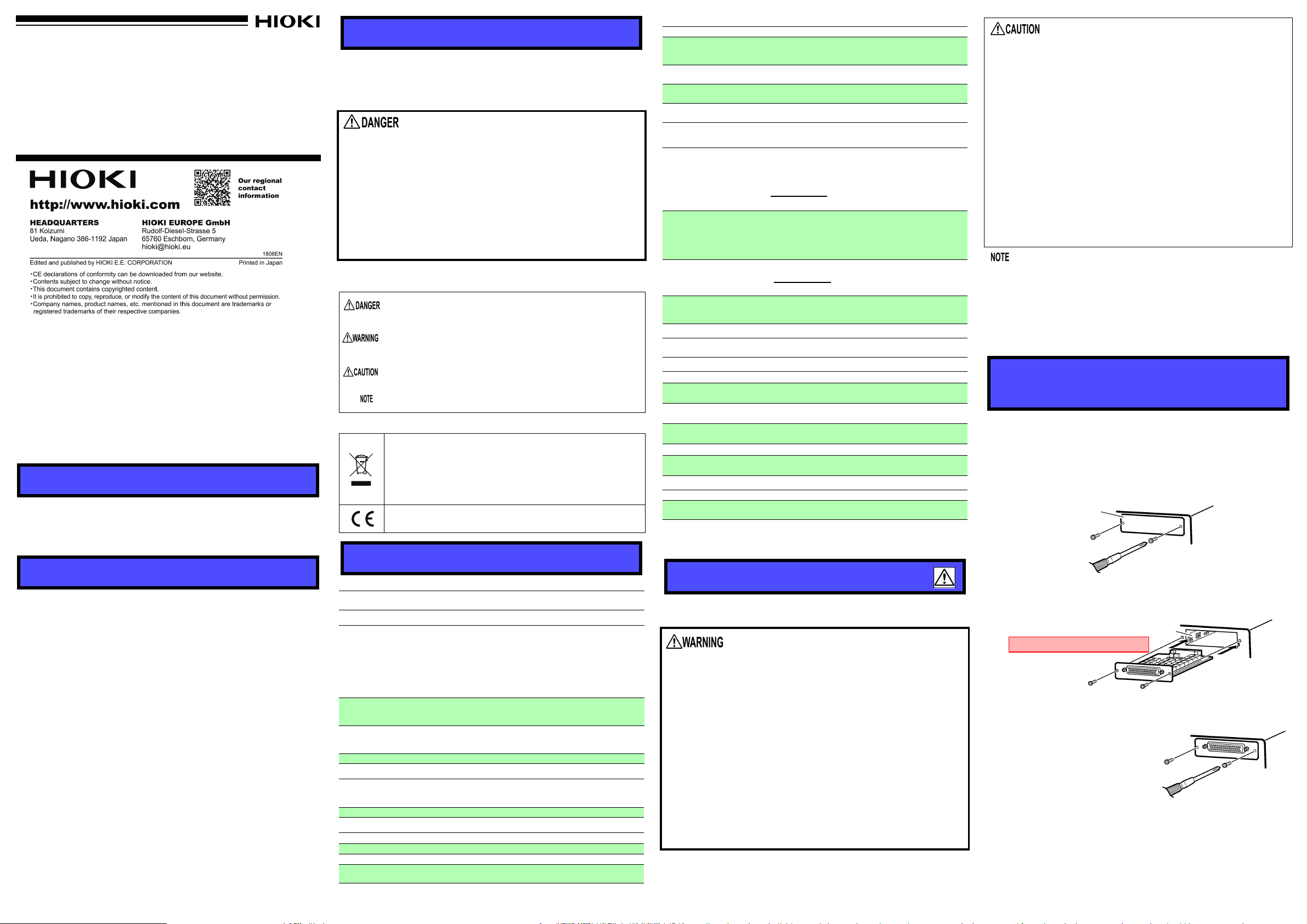
Installing and Removing the
Unit
Installing a Multiplexer Unit
Required item: One Phillips-head screwdriver
1 Turn off the instrument with the Z3003’s main power switch
and disconnect the cords and leads.
2 Remove the two screws with a Phillips head screwdriver
and remove the blank panel.
Blank panel
The rear panel of
the instrument
3 With attention to the orientation of the Multiplexer Unit, in-
sert it firmly all the way in. Insert the unit after aligning it with
the guide rail.
Guide rail
Do not directly touch the board
Model Z3003
When you insert the unit, taking countermeasures against static
electricity (using antistatic devices such as a wrist strap) as well
as wearing antistatic gloves are recommended.
4 Using the Phillips screwdriver,
tighten the two Multiplexer
Unit mounting screws.
For more information about settings, see the instrument manual
for the instrument with the Z3003.
Removing a Multiplexer Unit
After turning off the instrument with the Z3003’s main power
switch and disconnecting all cords and leads, remove the Multiplexer Unit by reversing the above procedure and then attach
the blank panel.
 Loading...