

Page 1

VT1005
HIOKI VT1005A971-00
AC/DC HIGH VOLTAGE DIVIDER
Power Analyzer Setup Guide
Oct. 2022 Edition 1 Printed in Japan
VT1005A971-00 22-10H
Introduction Features of Hioki Power Analyzer
Thank you for purchasing the Hioki VT1005 AC/DC High
Voltage Divider.
This Setup Guide describes the settings of the Hioki Power
Analyzer (PW8001, PW6001, PW3390) when they are used
with the VT1005.
Refer to the Instruction Manual of the Power Analyzer for
more information about how to use the Power Analyzer.
The latest edition of the Setup Guide
The contents of this Setup Guide are subject
to change, for example as a result of product
improvements or changes to specications.
The latest edition can be downloaded from
Hioki’s website.
https://www.hioki.com/global/support/download/
PW8001
Measurable band:
DC, 0.1 Hz to 5 MHz
(when the U7005 is used)
Up to eight-channel power measurement
with a single unit
PW6001
Measurable band:
DC, 0.1 Hz to 2 MHz
Up to six-channel power measurement with
a single unit
PW3390
Measurable band:
DC, 0.5 Hz to 200 kHz
Up to four-channel power measurement with
a single unit
EN
[600635520]
1. Setting the Scaling (VT Ratio/Rate)
Enter 1000 in the VT ratio/rate.
You can directly read values input from the VT1005 by setting the VT1005’s dividing ratio/rate to the Power Analyzer.
PW8001
Press the INPUT key. → Touch [CHANNEL].
→ Touch the channel detail display area.
PW6001
Press the INPUT key. → Touch [CHANNEL].
→ Touch the channel detail display area.
PW3390
Press the SYSTEM key. → Select [Input].
2. Setting the Phase Correction/Compensation Value
Phase correction/compensation for the Voltage Divider can be performed by setting a phase correction/compensation value
to the Power Analyzer to reduce power measurement errors in the high-frequency domain. The settings vary depend on the
Power Analyzer being used.
IMPORTANT
Enter a phase correction/compensation value correctly. Incorrect
settings may allow correction/compensation to increase measurement
errors.
2-1. When the PW8001 (Version 1.30 or later) is used
2-2. When the PW6001 or PW3390 is used
Please turn over. →
Page 2
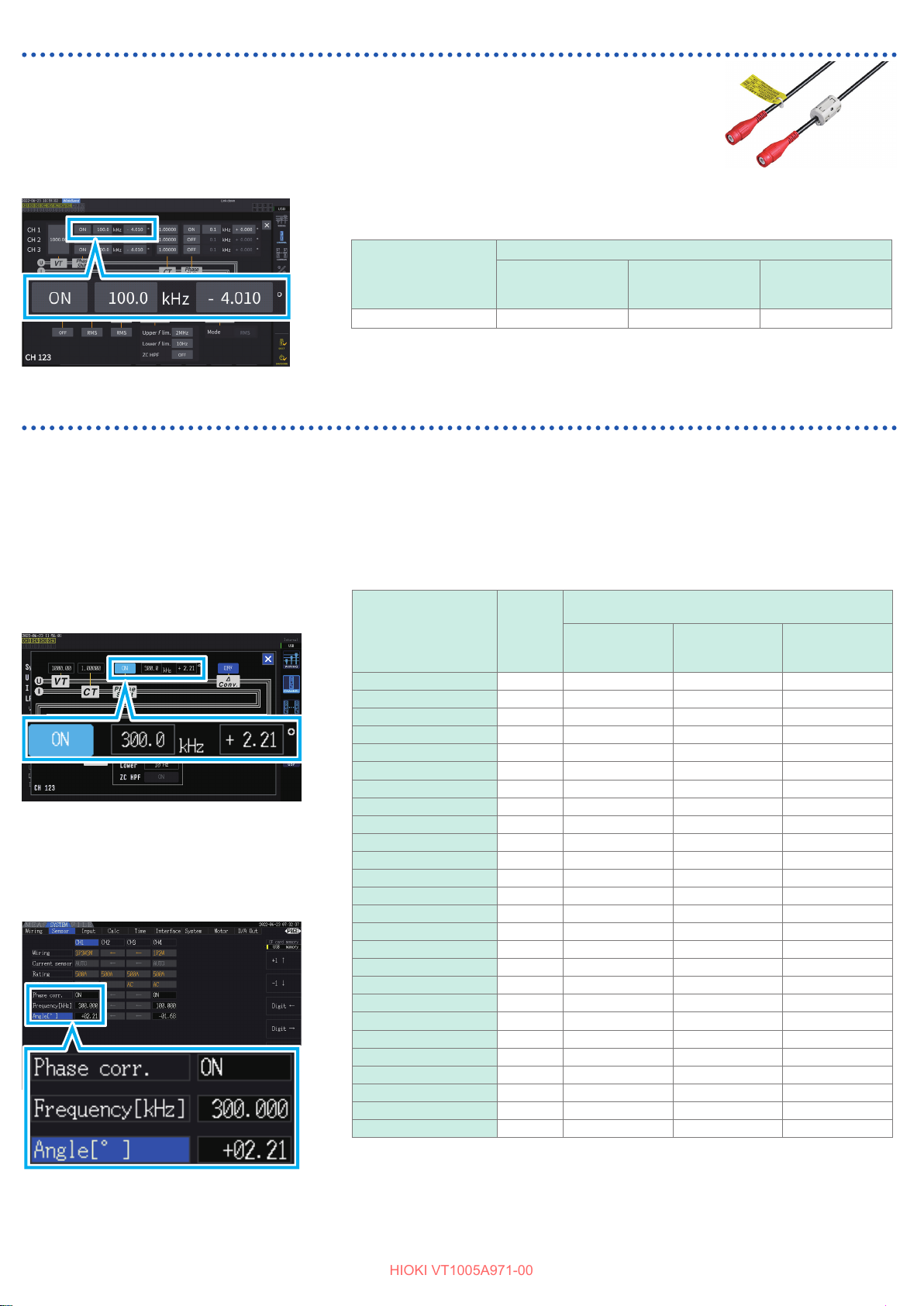
2-1. When the PW8001 (Version 1.30 or later) is used
HIOKI VT1005A971-00
Enable the voltage phase correction/compensation, and then
enter a correction/compensation value chosen from Table 1,
The phase correction/compensation value varies depending on the length of the L9217 Connection
Cord used with the VT1005.
Press the INPUT key. → Touch [CHANNEL].
→ Touch the channel detail display area.
L9217 Connection Cord
Table 1. Phase correction/compensation value (typical)
Typical between-input-and -output phase dierence value (degrees)
Frequency (kHz)
100.0 −4.01 −4.26 −5.52
Example: When the L9217 Connection Cord (1.6 m) is used with the V T1005
L9217
Connection Cord
(1.6 m)
L9217-01
Connection Cord
(3.0 m)
L9 217- 02
Connection Cord
(10 m)
2-2. When the PW6001 or PW3390 is used
Enable the current sensor phase correction/compensation, and then enter a
correction/compensation value chosen from Table 2.
The phase correction/compensation for the VT1005 and the current sensor can be performed by using the phase correction/
compensation function of the current sensor.
The phase correction/compensation value varies depending on the current censer to be used and the length of the L9217
Connection Cord used with the VT1005.
PW6001
Press the INPUT key. → Touch [CHANNEL].
→ Touch the channel detail display area.
Example: The CT6904 AC/DC Current Sensor is
used with the PW6001.
When the L9217 Connection Cord (1.6 m)
is used with the VT1005
PW3390
Press the SYSTEM key. → Select [Sensor].
Example: The CT6904 AC/DC Current Sensor is
used with the PW3390.
When the L9217 Connection Cord (1.6 m)
is used with the VT1005
Table 2. Phase correction/compensation value (typical)
Typical between-input-and -output phase dierence value
Model
CT 6841- 0 5 100.0 2.1 9 2.44 3.70
CT 6841A 100.0 0.42 0.67 1.93
CT6843-05 100.0 2.33 2.58 3.84
CT6843A 100.0 0.05 0.30 1. 56
CT6844 -05 50.0 0.72 0.84 1. 47
CT6844A 100.0 0.09 0.34 1. 60
CT6845 -05 20.0 0 .18 0.23 0.48
CT6845A 10.0 −0.54 −0 .51 −0.39
CT6846 -05 20.0 −1.09 −1.0 4 −0.79
CT6846A 10.0 −0.65 −0.62 − 0.50
CT6862-05 300.0 1.07 1.81 5.60
CT6863-05 100.0 −0.59 −0.34 0.92
CT6865-05 1.0 −1.17 −1.1 7 − 1.1 5
CT6872 10 0.0 2.73 2.98 4.24
CT6872-01 100.0 1. 38 1.63 2.89
CT6873 100.0 3.26 3 .51 4.77
CT6873- 01 100.0 1.91 2.16 3.42
CT6875, CT6875A 200.0 −2.43 −1.9 3 0.59
CT6875 -01, CT6875A-1 200.0 −4.85 −4.35 −1. 83
CT6876, CT6876A 200.0 −4.94 −4.44 −1.92
CT6876-01, CT6876A-1 200.0 −6.32 −5.82 −3.30
CT6877, CT6877A 100.0 1.38 1.6 3 2.89
CT6877-01, CT6877A-1 100.0 0.67 0.92 2.18
CT690 4 series*
9709 20.0 −0.31 − 0.26 − 0.01
PW9100 ser ies*
Assuming that the current sensor with the standard length cable is used, and the conductor under
measurement is positioned at the center of the sensor aperture.
*1: CT6904, CT6904-01, CT6904-60, CT6904-61, CT6904A, CT6904A-1, CT6904A-2,
CT6904A-3
*2: PW9100-03, PW9100-04, PW9100A-3, PW9100A- 4
1
2
Frequency
(kHz)
300.0 2 .21 2.95 6.74
300.0 9.23 9.97 13 .76
L9217
Connection Cord
(1.6 m)
(degrees)
L9217-01
Connection Cord
(3.0 m)
L9 217- 02
Connection Cord
(10 m)
 Loading...