

Page 1

SW1001
SW1002
Instruction Manual
SWITCH MAINFRAME
Be sure to read this manual
before using the device
When using the device for the
rst time
Part Names and Functions
Measurement Flowchart
Preparation for Measurements
June 2018 Edition 1
SW1001A961-00 18-06H
Safety Information
Troubleshooting
p. 8 Troubleshooting
p. 12 Error display and troubleshooting p. 126
p. 13
p. 4
p. 125
EN
Page 2

Page 3

Contents
Introduction
ConrmingPackageContents
Safety Information
Usage Notes
........................................................1
........................2
............................................4
......................................................4
1 Overview 7
1.1 Overview of Product
1.2 Features
1.3 Parts Names and Functions
1.4 Block Diagram
1.5 Glossary
1.6 Measurement Flowchart
...................................................7
................................................. 11
...............................7
.................8
.......................................10
......................12
2 Preparation for
Measurements
2.1 Connecting Instruments and
Controlling the Device
2.2 Installing the Module
2.3 Removing the Module
2.4 Connecting the Measurement Cable
2.5 Connecting the Connection Cable
TERMINAL 1
TERMINAL 2
TERMINAL 3
2.6 Setting the Communication Setting
Mode
2.7 Connecting the Power Cord
2.8 Turning on/off the Power
2.9 When the Power is Turned on
............................................20
............................................20
............................................21
......................................................22
13
..........................13
............................15
..........................16
.18
.....19
................23
.....................23
............24
3 Channel Switching 25
3.1 Inspection before Measurement
Inspecting the device and peripheral
devices
Checking for relay contact welding
3.2 Overview of Channel Switching
3.3 Procedure for Switching the Channel
Selecting the connection method
Switching the shield
Selecting the channel
3.4 Channel Switching Operation
3.5 Measurement between Two
Instruments
3.6 Precautions for Measurement
3.7 Channel Delay Function
.....................................................25
..................................29
................................30
............................................32
......................37
.........25
............26
..........27
28
...............28
.............31
............35
4 Scan Function 39
4.1 Overview of the Scan Function
4.2 Setting the Scan Channel
4.3 Setting the Trigger Source for
Scan Operation
4.4 Scan Operation
4.5 Resetting Scan Operation
4.6 Scan Measurement Example
.....................................40
.....................................41
..........39
...................40
...................42
.............43
5 Other Functions 45
5.1 Checking the Device Status
................45
6 Initialization 47
6.1 Initialization Settings
............................47
7 External Control (EXT.
I/O)
49
7.1 External Control Flow
7.2 Switching between Sinking Current
(NPN) and Sourcing Current (PNP)
7.3 Connection
Device connector and compatible
connectors
Signal Functions
Connection to the instrument
7.4 Timing Chart
Channel switching operation and scan
operation reset
7.5 InternalCircuitConguration
Electricalspecications
Connection examples
............................................51
................................................51
.......................................52
..........................................53
..........................................53
..........................49
...50
.....................52
..............55
.............................56
...............................57
8 Communication
Function
8.1 Interface Overview and Features
8.2 Setting the Communication Setting
......................................................59
Mode
8.3 LAN Interface
Communication condition settings
Setting LAN communications
Connecting the LAN cable
8.4 USB Interface
Installing the USB driver
Connecting the USB cable
59
.......59
........................................60
.............61
....................62
.........................63
........................................64
............................64
........................65
1
2
3
4
5
6
7
8
9
9
10
10
Index
SW1001A961-00
i
Page 4

Contents
8.5 RS-232C Interface
Connecting the RS-232C cable
Setting RS-232C communications
Setting the controller (PC, PLC, etc.)
................................66
.................66
.............68
.........68
8.6 Communication Command
Forwarding Function
8.7 Communication Method
Message format
Output queue and input buffer
Status Byte Register
Event Registers
Initialization items
Remote state
8.8 Message List
........................................71
........................................79
............................................86
.........................................87
8.9 Message Reference
Standard commands
Device-speciccommands
8.10 Sample Programs
Using Visual Basic® 5.0 or 6.0
Using Visual Basic® 2013
............................69
.......................71
...................76
.................................77
.....................................86
.............................90
.................................91
........................94
...............................107
.................107
........................ 111
9 Specications 119
9.1 SW1001, SW1002 General
Specications
9.2 SW1001, SW1002 Input
Specications/Output
Specications/Measurement
Specications
Basicspecications
9.3 SW1001, SW1002 Functional
Specications
9.4 SW1001, SW1002 Interface
Specications
LAN
........................................................123
USB
.......................................................123
RS-232C
EXT. I/O
..................................................124
...................................... 119
......................................120
................................120
......................................121
......................................123
................................................123
11 Multiplexer Module 129
11.1 SW9001 Multiplexer Module
(2-wire/4-wire)
Features
Specications
Switching wiring diagram
Connector wiring diagram
Acquiring the number of relay on/off
cycles
.................................................129
.....................................................134
.....................................129
.........................................129
.........................132
.......................133
11.2 SW9002 Multiplexer Module
(4-terminal pair)
Features
Specications
Switching wiring diagram
Connector wiring diagram
Acquiring the number of relay on/off
cycles
.................................................135
.....................................................140
11.3 Accuracy Calculation Example
..................................135
.........................................135
.........................138
.......................139
.........141
12 Appendix 143
12.1 Measurement cable
12.2 Measuring Object Short Circuit
due to Relay Contact Welding
12.3 Rack Mount
Rack mount bracket
L-shape bracket (For installing the
module in automated equipment)
.........................................147
12.4 Outline Drawings
SW1001
SW1002
.................................................152
.................................................153
Index 155
Warranty Certicate
............................143
..........145
................................148
............151
................................152
10 Maintenance and
Service
10.1 Troubleshooting
Before sending the device for repair
Error display and troubleshooting
10.2 List of Device Error Numbers
10.3 Repair and Inspection
ii
125
..................................125
........................128
........125
............126
............127
Page 5

Introduction
Introduction
Thank you for purchasing the Hioki SW1001, SW1002 Switch Mainframe. To obtain maximum
performance from the device over the long term, be sure to read this manual carefully and keep it
handy for future reference.
With the optional multiplexer module (hereafter referred to as “module”) installed on this device, the
input of multiple channels can be switched to one or two measuring instruments (hereafter referred
to as simply “instrument”).
Modules can be installed in 3 slots for the SW1001 and 12 slots for the SW1002. Other functions
are common for all the models.
1
2
Be sure to also read the separate document “Operating Precautions” before use.
Target audience
This manual has been written for use by individuals who use the product in question or who teach
others to do so. It is assumed that the reader possesses basic electrical knowledge (equivalent to
that of someone who graduated from the electrical program at a technical high school).
Trademarks
Windows, Visual Studio and Visual Basic are either registered trademarks or trademarks of
Microsoft Corporation in the United States and other countries.
Notations
*
[ ]
POWER
(Bold)
(p. ) Indicates the location of reference information.
Additional information is presented below.
Menus, dialog boxes, buttons in a dialog box, and other names on the screen are
indicated in brackets.
Indicates the names and keys on the screen and the device in boldface.
3
4
5
6
7
Accuracy
We dene measurement tolerances in terms of f.s. (full scale), rdg. (reading), and dgt. (digit) with
the following meanings.
f.s.
rdg.
dgt.
(maximum display value or range)
The maximum display value.
(reading or displayed value)
The value currently being measured and indicated on the instrument.
(resolution)
The smallest displayable unit on a digital measuring device, i.e., the input value that
causes the digital display to show a “1” as the least-signicant digit.
8
9
10
Appx. Ind.
1
Page 6
Conrming Package Contents
Conrming Package Contents
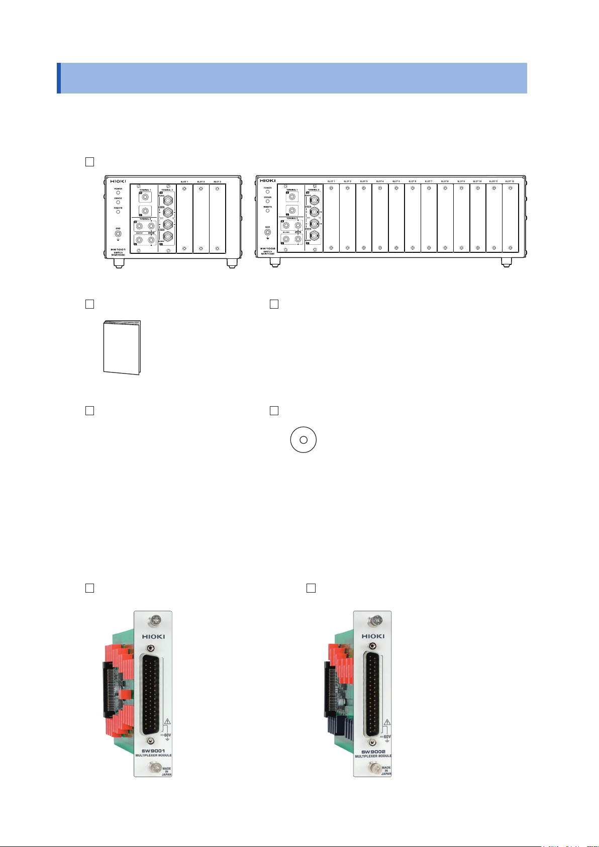
Main unit and accessories
Conrm that these contents are provided.
Model SW1001 or SW1002 Switch Mainframe
Instruction Manual (this document) Power cord
Operating Precautions (0990A905) CD (USB driver)*
* The latest version can be downloaded from our
web site.
Options
The following options are available for the device. Contact your authorized Hioki distributor or
reseller when ordering.
Module
Model SW9001 Multiplexer Module
(2-wire/4-wire)
Model SW9002 Multiplexer Module
(4-terminal pair)
2
Page 7
Conrming Package Contents
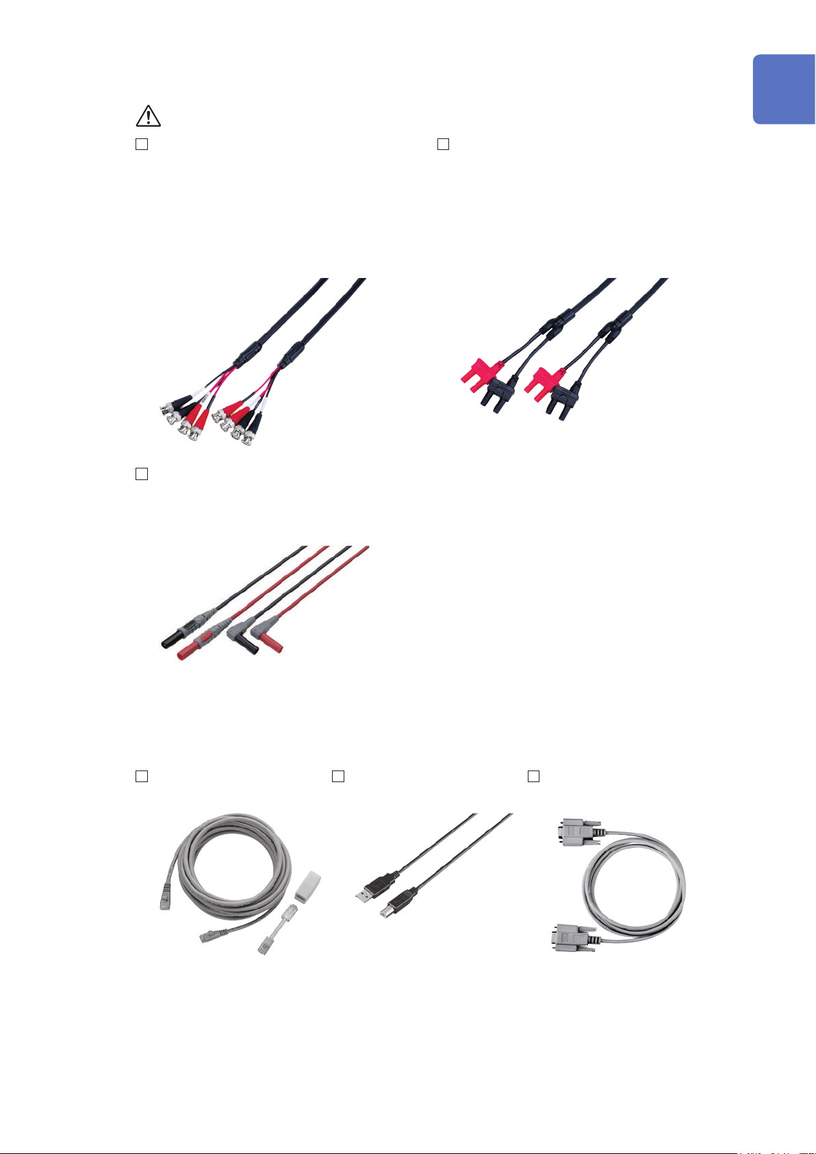
Connection cable
See: “Before measurement” (p. 5)
Model L2004 Connection Cable Model L2108 Connection Cable
Length: Approx. 910 mm Length: Approx. 840 mm
Maximum rated voltage: 30 V peak Maximum rated voltage: 60 V DC, 30 V AC rms,
42.4 V peak
Maximum rated voltage
to earth:
30 V DC or less, no
measurement category
Maximum rated voltage
to earth:
60 V DC or less, no
measurement category
1
Maximum rated current: 2.5 A peak Maximum rated current: 2 A peak
Model L4930 Connection Cable Set
Length: Approx. 1.2 m
Maximum rated voltage*: CAT III: 1000 V
CAT IV: 600 V
2
3
4
5
6
* Do not input voltage exceeding the rating of this device and the instrument.
Communications cable
Model 9642
LAN Cable
Model L1002
USB Cable (A-B)
7
8
Model 9637
RS-232C Cable (9pin-9pin/1.8 m)
9
10
Appx. Ind.
3
Page 8
Safety Information
Safety Information
Be sure to also read the separate document “Operating Precautions” before use.
Usage Notes
Check before use
Follow these precautions to ensure safe operation and to obtain the full benets of the various
functions.
WARNING
If a connection cable or the device is damaged, there is a risk of an electric shock.
Perform the following inspection before using the device.
• Before using the device, check that the coating of the connection cables are
neither ripped nor torn and that no metal parts are exposed. Using the device
under such conditions could result in an electric shock. Replace any damaged
cable with a new one.
• Before using the device the rst time, verify that it operates normally to ensure
that no damage occurred during storage or shipping. If you nd any damage,
contact your authorized Hioki distributor or reseller.
This device is designed to measure voltages of 60 V or lower. Do not input
voltages over 60 V or measure locations exceeding 60 V from the ground potential.
If the relay of the device fails, the battery of the measuring object may be shorted
(p. 145).
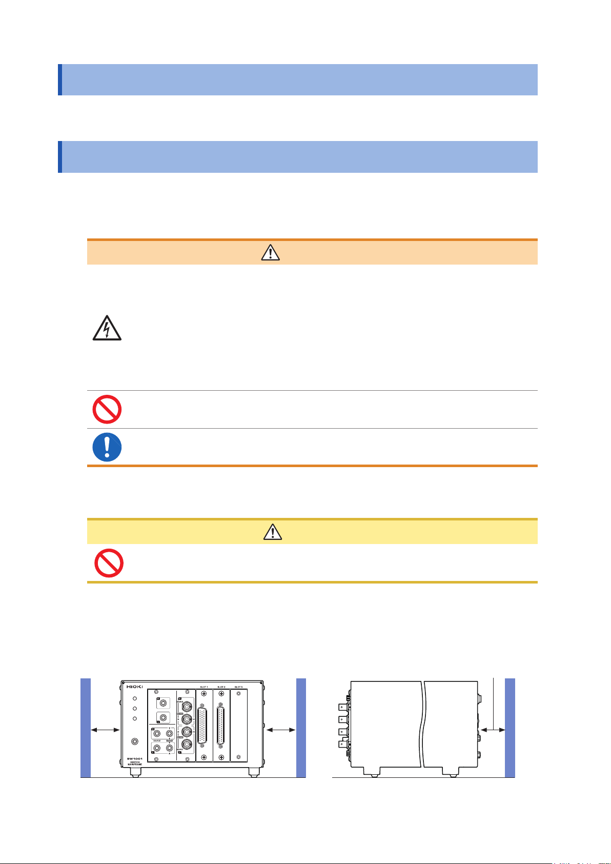
Installing the device and module
CAUTION
Do not position the device on an unstable table or inclined surface. Dropping or
knocking down the device can cause injury or damage to the device.
Installing
To prevent overheating, be sure to leave the specied clearances around the device.
• The device should be operated only with the bottom side downwards.
Rear: 10 mm or moreSide: 50 mm or more
4
Page 9
Handling the device
This device may cause interference if used in residential areas. Such use must be avoided unless
the user takes special measures to reduce electromagnetic emissions to prevent interference to the
reception of radio and television broadcasts.
Before installing the module
WARNING
• To prevent an electric shock, before removing or replacing a module, conrm
that the device is turned off and that all the measurement cables, connection
cables, and the power cord are disconnected.
• Installing a module while the device is turned on may prevent detection of
the contact state of relays on the module or result in short-circuiting of the
measuring object. Damage of the device or module may cause the measuring
object to be shorted or the instrument to fail.
• Be careful about short circuits when connecting a measuring object with
electromotive force (battery, power supply, etc.).
• The maximum voltage of the device contact is 30 V (rms value) and 42.4 V (peak
value) or 60 V (direct current). Do not directly connect a withstand voltage tester
or an insulation resistance tester.
Usage Notes
1
2
3
4
When installing or removing the module, be sure to observe the following precautions:
• Touch the GND terminal of the device with your hand to release static and then use
antistatic gloves to perform procedures.
• Hold the sheet metal area of the module. Directly touching the board with your hand may
damage the circuit board due to static. If the measurement target has high resistance, the
error component due to factors such as oil from your ngers may increase in magnitude.
Before measurement
•
Do not short-circuit between electrodes or terminals using a probe when
measuring the battery or capacitor. Doing so may cause an electric arc, resulting
in serious injury.
• Do not use the device or the connection cables that exceed its ratings or
specications. Doing so may damage the device or cause it to become hot,
resulting in a bodily injury.
• Do not use the instrument to be used in conjunction with the device outside of
its ratings or specications. Doing so may damage the instrument or cause it to
become hot, resulting in a physical injury.
CAUTION
5
6
7
DANGER
8
9
10
WARNING
The maximum rated voltage between the module and ground is 60 V DC. To avoid
an injury and damage to the device, ensure that voltage between channels never
exceeds this limit. Prevent the voltage potential difference of the entire system
from exceeding 60 V DC.
The measurement connector frame of the module is connected to the casing (metal) of the device
as well as the protective ground terminal of the power inlet (conductive).
Appx. Ind.
5
Page 10
Usage Notes
Before starting the external control
WARNING
To prevent an electric shock or damage to the device, always observe the
following precautions when connecting the cables to the EXT. I/O terminals.
• Always turn off the device and any devices to be connected before making
connections.
• Be careful to avoid exceeding the signal ratings of the EXT. I/O terminals.
• During operation, a wire becoming dislocated and contacting another
conductive object can be a serious hazard. Use screws to secure the external
connectors.
• Ensure that devices and systems to be connected to the EXT. I/O terminals are
properly isolated from one another.
Before connecting the communications cables
CAUTION
• Use a common ground for both the device and the PC. Using different ground circuits
will result in a potential difference between the device's ground and the computer's
ground. If the communications cable is connected while such a potential difference
exists, it may result in device malfunction or failure.
• Before connecting or disconnecting any communications cables, always turn off the
device and the PC. Failure to do so could result in equipment malfunction or damage.
• After connecting the communications cables, tighten the screws on the connector
securely. Failure to secure the connector could result in device malfunction or damage.
• To avoid device failure, do not disconnect the communications cables while
communications are in progress.
Precautions during shipment
Store the packaging in which the device was delivered, as you will need it when transporting the
device.
Disc precautions
• Exercise care to keep the recorded side of discs free of dirt and scratches. When writing text on
a disc’s label, use a pen or marker with a soft tip.
• Keep discs inside a protective case and do not expose to direct sunlight, high temperature, or
high humidity.
• Hioki is not liable for any issues your computer system experiences in the course of using this
disc.
6
Page 11

1
Overview
1.1 Overview of Product
This device is a module type switching system that is ideal for multi-channel measurement of
batteries. You can choose a main frame from two choices according to the required number of
channels. You can also choose a module from two module types according to the instrument to be
used with the device (2-wire/4-wire module and 4-terminal pair module).
1.2 Features
Reduction of errors when measuring internal resistance
When AC low resistance measurement is performed using the BT4560 Battery Impedance Meter
or the BT3562 Battery HiTester, the inuence of electromagnetic induction (eddy current) on the
measured value can be minimized.
Ability to switch measurement between two instruments
For example, you can connect a BT3562 and DM7276 to the device and use it to switch between
internal resistance measurement and high-precision OCV measurement.
Protection against short circuit with fuses
To protect batteries to be measured if a short circuit occurs in a channel, a protective fuse is built
into each channel.
1
Overview
7
Page 12
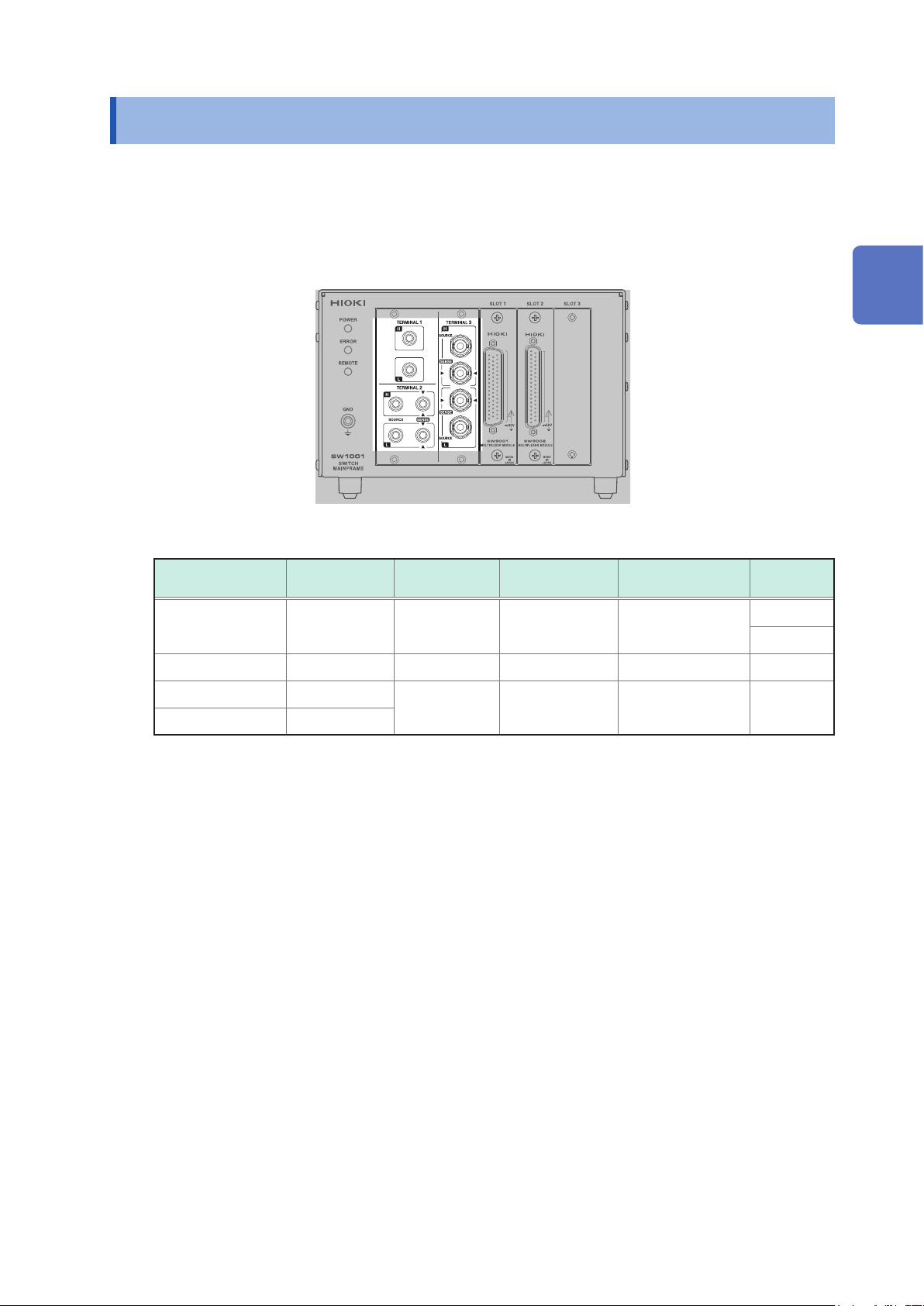
Parts Names and Functions
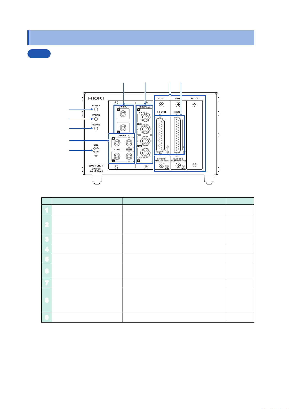
1.3 Parts Names and Functions
Front
The illustration shown here is for the SW1001.
4
6 7
8
1
2
3
5
9
No. Name Description Reference
POWER lamp Lights up when the main frame power is on. p. 23
1
Lights up for self-test at the time of startup and
ERROR lamp
2
REMOTE lamp Lights up when communications data is received. p. 86
3
TERMINAL 1 Used to connect a 2-wire instrument. p. 20
4
TERMINAL 2 Used to connect a 4-wire instrument. p. 20
5
TERMINAL 3
6
SLOT 1 to SLOT 3 Used to attach the module. p. 15
7
Measurement cable connector
8
GND terminal Ground for the device. Connected to the ground. p. 36
9
when an error, such as a communications error,
occurs.
Used to connect a 4-terminal pair (BNC terminal)
instrument.
Used to connect the measurement cable to each
module. For more details, see the chapter for the
multiplexer module.
p. 23
p. 126
p. 21
p. 5
p. 18
p. 133
p. 139
8
Page 13
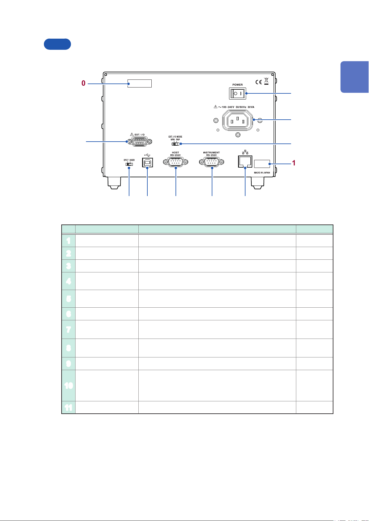
Rear
The illustration shown here is for the SW1001.
Parts Names and Functions
10
1
2
3
4
11
6 7 8 9
5
No. Name Description Reference
Power switch Turns on/off the power. p. 23
1
Power inlet Used to connect the provided power cord. p. 23
2
1
Overview
EXT. I/O terminal Used to connect the device to be externally controlled. p. 51
3
EXT. I/O MODE
4
change-over switch
Communication
5
setting mode switch
USB connector Used to connect the PC. p. 64
6
HOST
7
RS-232C connector
INSTRUMENT
8
RS-232C connector
LAN connector Used to connect the PC. p. 60
9
Serial number
10
MAC address MAC address of the LAN. p. 105
11
Left: Sinking current (NPN), Right: Sourcing current (PNP) p. 50
Perform communication using xed settings when the
communication settings are unknown.
Used to connect the PC. p. 66
Used to connect the RS-232C connector of the instrument for
scan measurement.
The serial number consists of 9 digits. The rst two (from
the left) indicate the year of manufacture, and the next two
indicate the month of manufacture.
Required for production control. Do not peel off the label.
p. 22
p. 70
–
9
Page 14
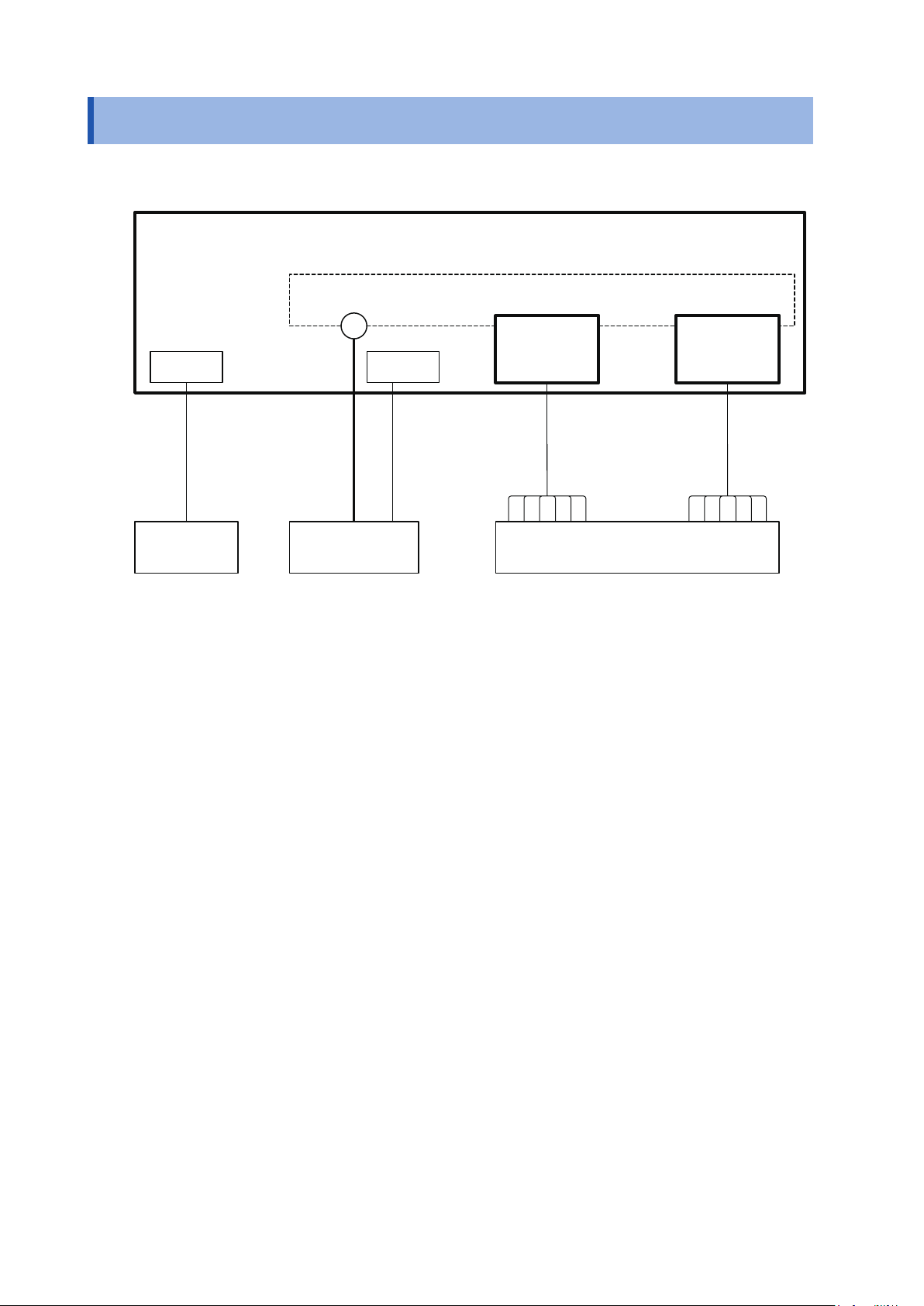
Block Diagram
1.4 Block Diagram
The conguration of this device is shown in the following block diagram.
Switch Mainframe
Internal analog bus
Terminal Module
I/F EXT. I/O
Connection cable Measurement cable
PC/PLC
Instrument Measuring object
...
Module
10
Page 15

1.5 Glossary
Terms Description Reference
Measurement cable Connects the measuring object and the module.
It is prepared by the customer.
Connection cable Connects the switch mainframe and instrument.
Prepare the optional cable.
Glossary
p. 143
p. 19
1
Overview
Terminal Connects the instrument.
The terminal to be used varies depending on the connection method
(2-wire/4-wire/4-terminal pair)
Module For the switching circuit.
The connection method varies depending on the module type.
Slot Used to attach the module.
The number of slots varies depending on the switch mainframe type.
Channel Channel inside the module.
Specify the slot and channel and select the measuring object.
Analog bus Common analog signal inside the switch mainframe.
The analog buses for 4 systems are built in.
The analog bus to be used is determined based on the connection
method.
Channel relay Switches the channel inside the module. p. 27
Bus relay Connects the measurement signal selected for the channel relay to
the analog bus.
It is built into the module.
Switching the bus relay allows you to select the connection method.
Connection method You can select the measurement connection from 2-wire, 4-wire, or
4-terminal pair.
Selecting a connection method determines the connection terminal for
the instrument.
p. 28
p. 129
p. 30
p. 30
p. 27
p. 27
p. 28
Shield For the measurement cable (cable for the measuring object).
The destination to which the shield is connected inside the module
can be switched.
Switching the connection destination can reduce the inuence of
noise depending on the instrument to be used or the measurement
environment.
Scan Switches the pre-registered channel (scan list) in sequence.
Connecting the instrument and this device using EXT. I/O enables
the channel to be switched and trigger measurement to be performed
automatically.
p. 29
p. 39
11
Page 16

Measurement Flowchart
1.6 Measurement Flowchart
Thoroughly read “Usage Notes” (p. 4) beforehand.
Installation, connection, and turning on of power
Installing the device. (p. 4)
Attaching the module to the device. (p. 15)
Connecting the measurement cable to the module. (p. 18)
Connecting the device and the instrument using the connection cable. (p. 19)
Connecting the communications cable and making settings.
• Set the communication setting mode (p. 22).
• Connect the LAN, USB, or RS-232C cable to the PC (p. 59).
Connecting the device and the external control device. (for scan measurement)
• Connect the device to an external device such as a PLC using EXT. I/O (p. 49).
Connecting the power cord. (p. 23)
Turning on the power. (p. 23)
Inspection before measurement (p. 25)
Setting before measurement
Selecting the module connection method. (p. 28)
Switching the shield. (p. 29)
Selecting the channel to be measured. (p. 30)
Starting the measurement
12
Sending a measurement command to the instrument.
Receiving measurement results.
• For information on the measurement processing and receiving measurement results, see the
instruction manual of the instruments to be used.
Ending the measurement
Turning off the power. (p. 23)
Page 17
2
Preparation for Measurements
2.1 Connecting Instruments and Controlling the Device
This section describes how to connect one or more measuring instruments and control the device.
A PC or PLC must be connected in order to control the device. A PC or PLC connection is also
required in order to control instruments and acquire measured values.
The device utilizes the connection and control methods described below.
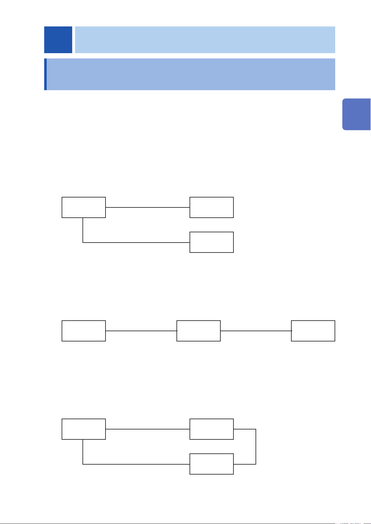
Basic control
Connect the PC to the device and instrument via separate communications interfaces.
Control the device to switch channels and control the instrument to congure settings, perform
measurement, and acquire measured values.
See: “3.2 Overview of Channel Switching” (p. 27)
2
Preparation for Measurements
PC
LAN/USB/RS-232C
LAN/USB/RS-232C
SW1001
Instrument
Controlling an instrument via the device
You can also use the device’s functionality for forwarding communication commands to control
instruments simply by sending commands to the device.
See: “8.6 Communication Command Forwarding Function” (p. 69)
INSTRUMENT
PC
LAN/USB/RS-232C
SW1001
connector
RS-232C only
Performing automatic scan measurement using EXT. I/O
You can switch channels and perform a series of measurements in accordance with a previously
created scan list by connecting the device and an instrument via the EXT. I/O interface. You can
also acquire measured values by using the instrument’s data output function (to automatically send
measured values) or memory function.
See: “4 Scan Function” (p. 39)
Instrument
PC
LAN/USB/RS-232C
SW1001
EXT. I/O
Instrument
LAN/USB/RS-232C
13
Page 18
Connecting Instruments and Controlling the Device
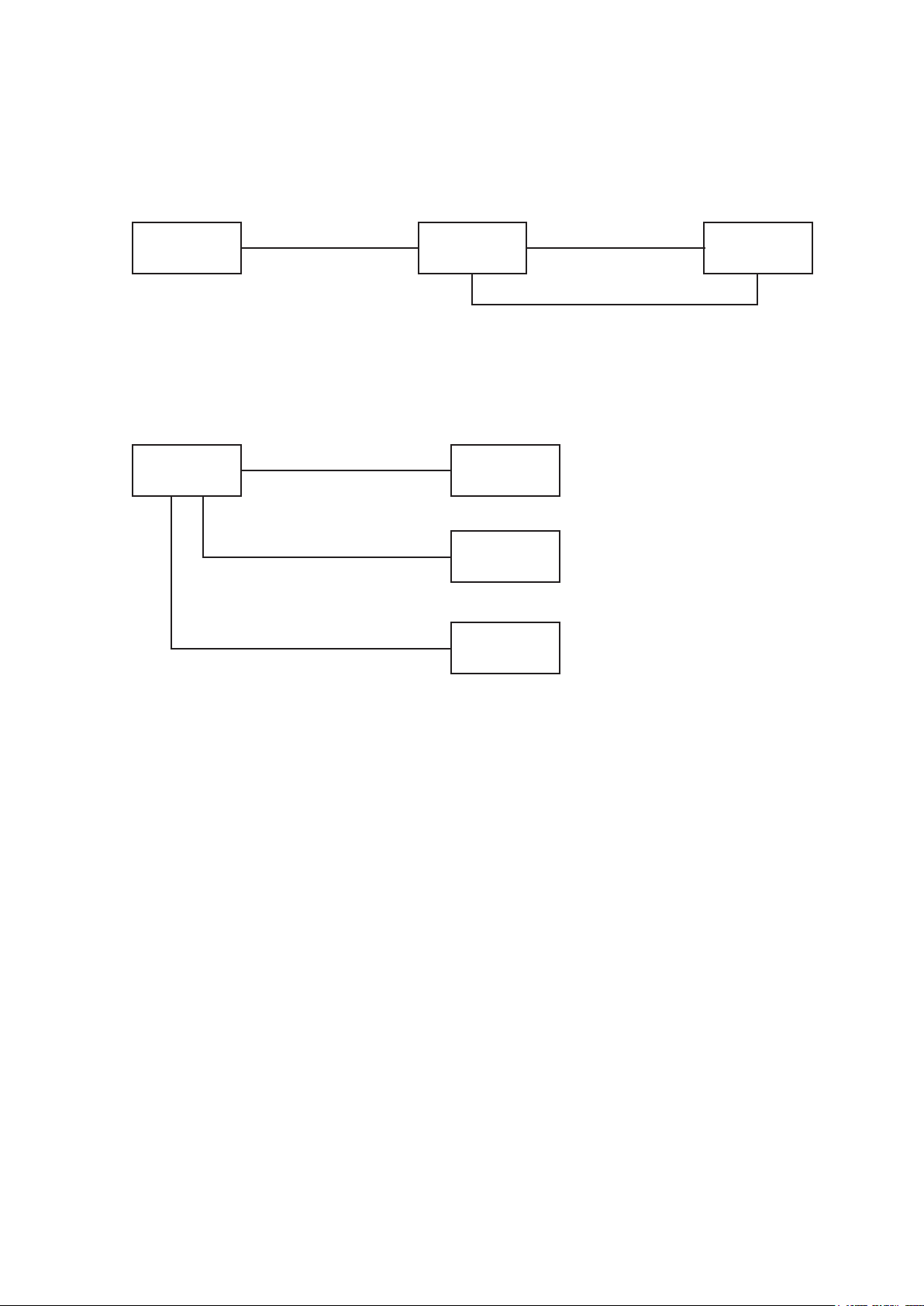
Performing automatic scan measurement using EXT. I/O
(using the communication command forwarding function)
Furthermore, you can perform automatic scan measurement over a single communications
interface by using the device’s communication command forwarding function.
INSTRUMENT
PC
LAN/USB/RS-232C
SW1001
connector
RS-232C only
EXT. I/O
Connecting two instruments
You can perform measurement by connecting two instruments to the device.
See: “3.5 Measurement between Two Instruments” (p. 32)
Instrument
PC
LAN/USB/RS-232C
SW1001
Instrument 1
LAN/USB/RS-232C
Instrument 2
LAN/USB/RS-232C
14
Page 19
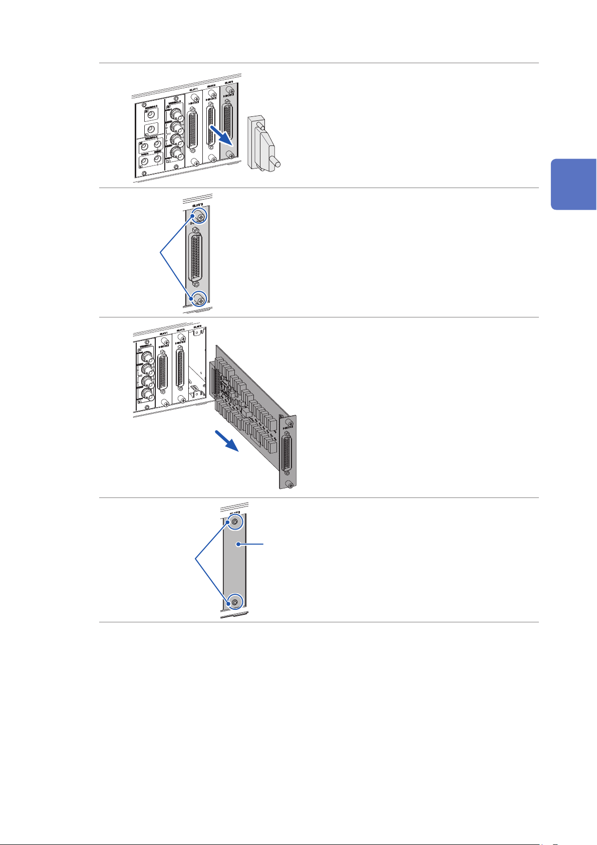
Installing the Module
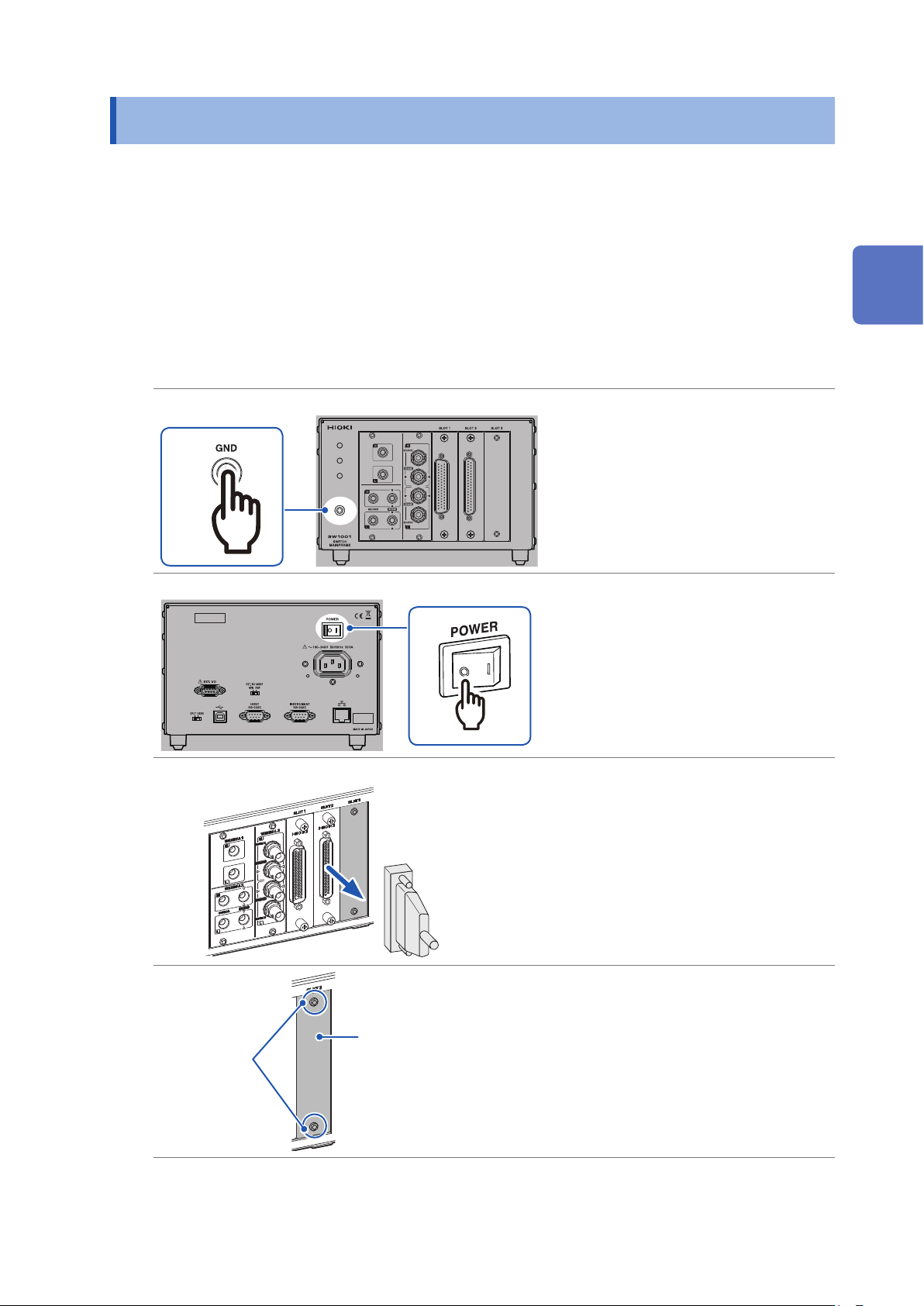
2.2 Installing the Module
Thoroughly read “Before installing the module” (p. 5) beforehand.
The following settings are initialized when you install a new module into a slot or change the type of
module installed in a given slot.
• Connection method
• Shield switching
• Channel delay
• Scan list
Required items: Phillips screwdriver (No. 2), antistatic gloves
2
Preparation for Measurements
1
Rear
Front
Front
3
Touch the GND terminal with
1
bare hands.
Wear antistatic gloves.
2
Turn off the device.
3
Remove all the measurement
4
cables connected to the device
and module.
(To prevent electric shock and short
circuit of the measuring object.)
Screw
(M3 × 6 mm)
Blank panel
Loosen the two screws
5
(M3 × 6 mm) and then remove
the blank panel.
Store the blank panel and screws.
You need the screws when using the
device after removing the module.
15
Page 20
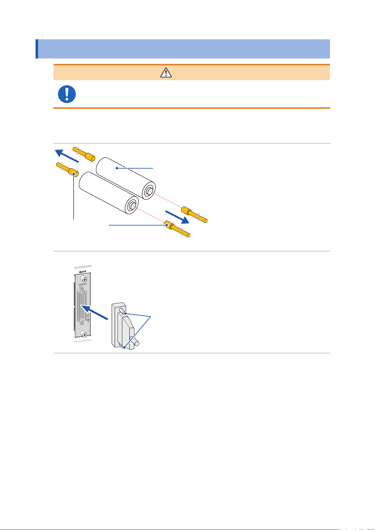
Removing the Module
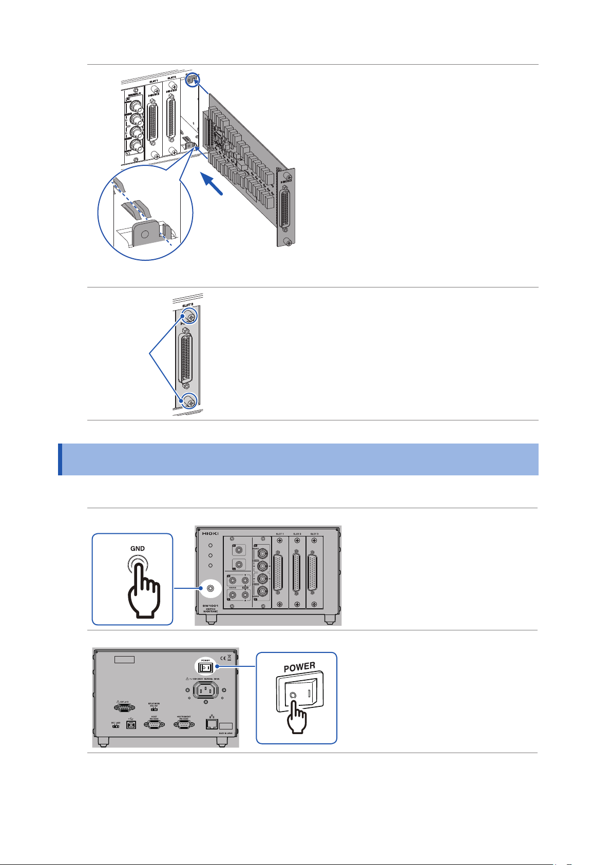
Align with the guide rail
Insert the module to the back.
6
Tighten the two screws to
7
secure the module in place.
Screw
2.3 Removing the Module
Required items: Phillips screwdriver (No. 2), antistatic gloves
Front
1
Rear
Touch the GND terminal with
1
bare hands.
Wear antistatic gloves.
2
Turn off the device.
3
16
3
Page 21
Removing the Module
Front
Screw
Remove all the measurement
4
cables connected to the
device and module.
(To prevent electric shock and short
circuit of the measuring object.)
Loosen the two screws.
5
Pull out the module.
6
2
Preparation for Measurements
Screw
(M3 × 6 mm)
Blank panel
Attach the blank panel and
7
tighten the two screws
(M3 × 6 mm) to secure the
panel.
17
Page 22
Connecting the Measurement Cable
2.4 Connecting the Measurement Cable
WARNING
Connect the measurement cable with the measuring object disconnected from
the measurement cable. The measuring object may be shorted depending on the
condition of the module switching circuit.
Please provide a suitable measurement cable.
See: “12.1 Measurement cable” (p. 143)
Turn off the device.
1
Disconnect the probe from the
Disconnect
Measuring object
2
measuring object.
Disconnect
Tip of the probe
Front
Connect the measurement
3
cable connector to the module’s
connector.
Secure the measurement cable
4
connector using the screws.
3
4
For information on connecting the measuring object, see the instruction manual of each instrument.
18
Page 23
Connecting the Connection Cable
2.5 Connecting the Connection Cable
The connection cable is optional (p. 2).
Connect the device to the instrument.
For information on connecting the instrument, see the instruction manual of each instrument.
Front
2
Preparation for Measurements
Select the terminal and connection cable to be connected based on the instrument to be connected.
Instrument
example
Voltmeter DM7276 TERMINAL 1 L4930 2-wire
Battery tester BT3562 TERMINAL 2 L2108 4-wire SW9001
Battery tester BT4560
LCR meter IM3590
Model Terminal
TERMINAL 3 L2004 4-terminal pair SW9002
Connection
cable
Connection
method
Module
SW9001
SW9002
19
Page 24

Connecting the Connection Cable
TERMINAL 2 and TERMINAL 3 are internally conducted. Do not connect the instrument
to TERMINAL 2 and TERMINAL 3 at the same time. Doing so may damage the
instrument.
TERMINAL 1
Turn off the device.
1
Connect the connection cable to TERMINAL 1.
2
CAUTION
Front
Connect the other end of the connection cable to the instrument.
3
TERMINAL 2
Turn off the device.
1
Connect the connection cable to TERMINAL 2.
2
Connect the connection cable so that the red
lead wire match and the black
match.
Red
Black
H
L
mark of the device and the
mark of the device and the
Front
mark of the black lead wire
mark of the red
20
H
Red
L
Black
Connect the other end of the connection cable to the instrument.
3
Page 25

TERMINAL 3
Turn off the device.
1
Connect the connection cable to TERMINAL 3.
2
Connecting the Connection Cable
Match the cable and the connection
terminal signal.
SOURCE-H (red)
SENSE-H (red)
SENSE-L (black)
SOURCE-L (black)
1. Check the direction of
the grooves of the BNC
connector. The grooves
should t into the connector
guide of the device.
Device side
Connector guide
Front
2. Align the grooves of the
BNC connector with the
connector guide of the
device and insert the BNC
connector.
2
Preparation for Measurements
3. Turn the BNC connector to
the right to lock it.
BNC connector grooves of
the connection cord
Connect the other end of the connection cable to the instrument.
3
Connection cable terminal
SOURCE-H (red) SOURCE-H (red) Hcur
SENSE-H (red) SENSE-H (red) Hpot
SENSE-L (black) SENSE-L (black) Lpot
SOURCE-L (black) SOURCE-L (black) Lcur
BT4560 IM3590
Instrument terminal
21
Page 26
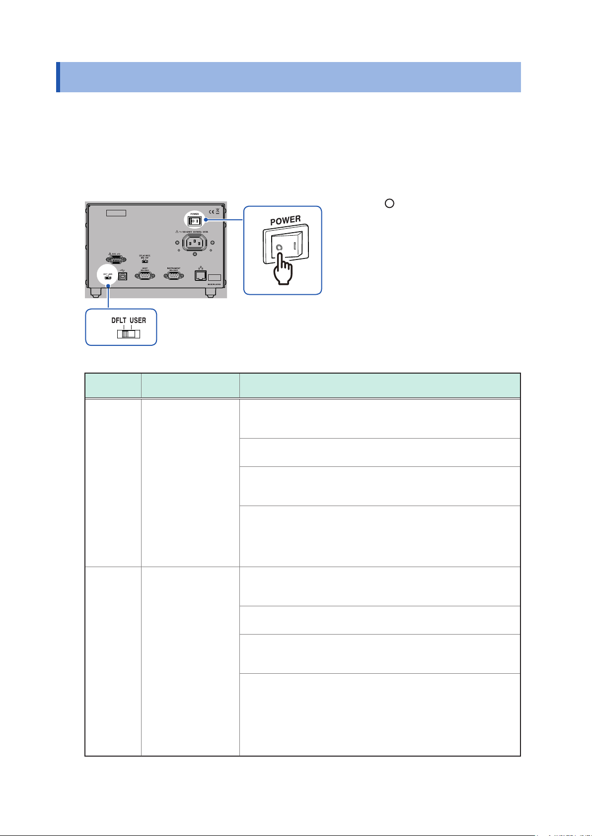
Setting the Communication Setting Mode
2.6 Setting the Communication Setting Mode
The device uses the communications interface for control.
You can select the xed setting mode for initial communication settings or the user setting mode for
user settings using the switch on the rear of the device.
Specify the communication settings according to the interface to be used in the user setting mode.
Reference: “8.1 Interface Overview and Features” (p. 59)
Rear
Check that the power switch is
1
off ( ).
Change the communication
1
2
setting mode using the
communication setting mode
switch.
2
Switch
DFLT Fixed setting mode All of USB, RS-232C, and LAN can be used.
Communication
setting mode
Device setting description
Communications are performed using the specied communication
settings.
• USB
No setting item
• RS-232C
Transmission speed: 9600 bps, data bits: 8; stop bit: 1; parity
check: none; ow control: none
• LAN
IP address: 192.168.0.254
Subnet mask: 255.255.255.0
Default gateway: 0.0.0.0 (None)
Communication command port number: 23
USER User setting mode All of USB, RS-232C, and LAN can be used.
Use the communication settings that are specied using the following
communication commands.
• USB
No setting item
• RS-232C
:SYSTem:COMMunicate:RS232C:SPEED <
Reference: “(8) RS-232C settings” (p. 103)
• LAN
:SYSTem:COMMunicate:LAN:IPADdress <
:SYSTem:COMMunicate:LAN:SMASk <
:SYSTem:COMMunicate:LAN:GATeway <
:SYSTem:COMMunicate:LAN:CONTrol <
:SYSTem:COMMunicate:LAN:UPDate
Reference: “(9) LAN settings” (p. 103)
Subnet mask
Transmission speed
IP address
Gateway address
Port No.
>
>
>
>
>
22
Page 27
Connecting the Power Cord
2.7 Connecting the Power Cord
Be sure to thoroughly read the separate document “Operating Precautions” before use.
Rear
1
Power inlet
2
2.8 Turning on/off the Power
Check that the power switch is
1
off ( ).
Check that the power voltage is
2
within the range indicated on the
rear of the device and connect
the power cord to the power
inlet.
Connect the plug of the power
3
cord to the outlet.
2
Preparation for Measurements
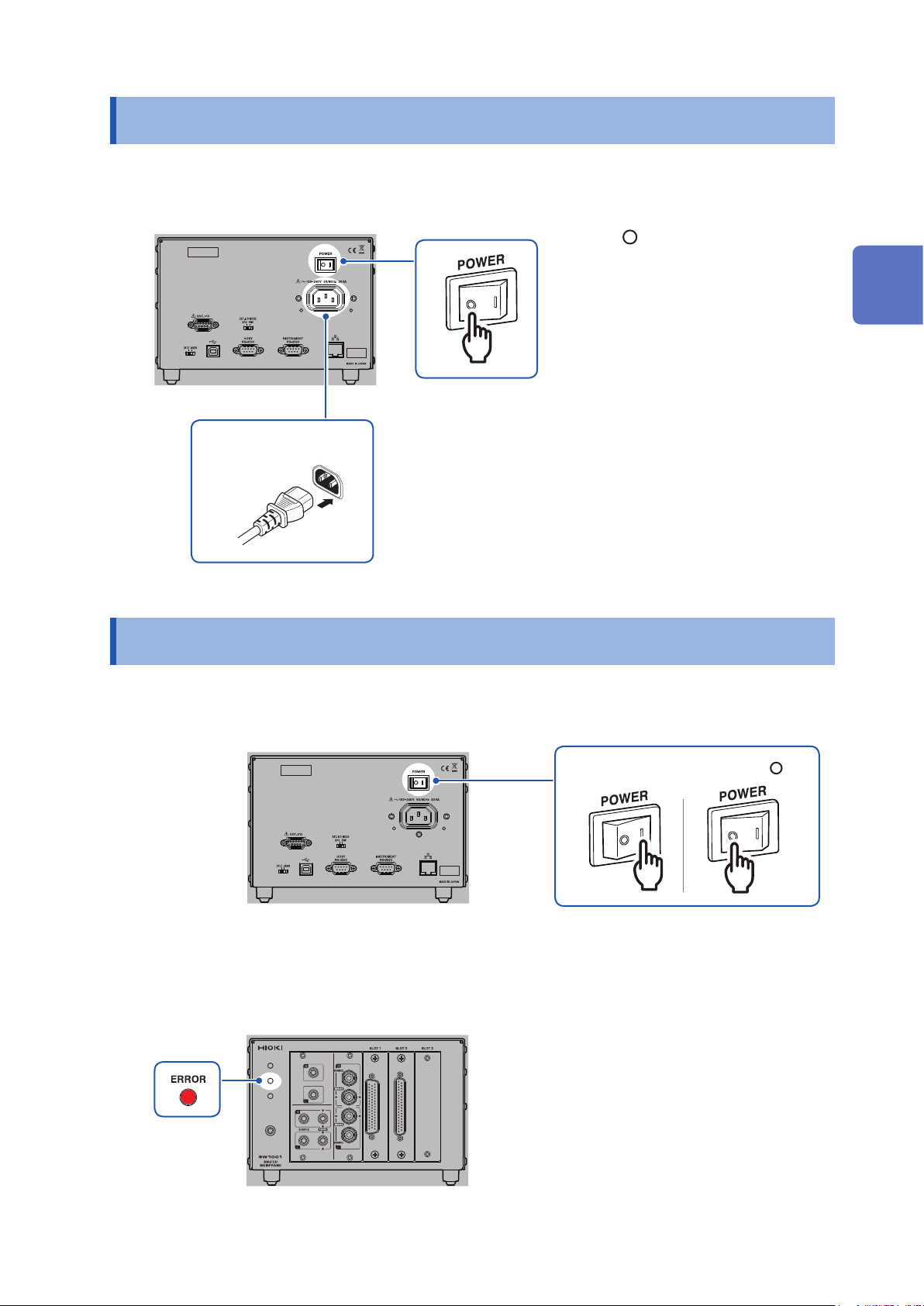
Use the power switch on the rear of the device to turn on/off the power.
Rear
Power off ( )Power on (I)
The front POWER lamp lights up when the device is turned on, and a self-test is executed.
When an error occurs, the ERROR lamp on the front lights up. If an error occurs during self-test,
communications and control using EXT. I/O become disabled.
Front
23
Page 28

When the Power is Turned on
2.9 When the Power is Turned on
Item Initialization description
Channel relay All relays open
Bus relay All relays open
EXT. I/O CLOSE output signal Off
Connection method Settings (for each slot) are saved with the settings backup command.
Shield switching Settings (for each slot) are saved with the settings backup command.
Scan settings Settings are saved with the settings backup command.
Channel delay settings Settings are saved with the settings backup command.
Communication settings Settings are saved with the settings backup command.
See: “Backing up settings” (p. 105)
24
Page 29
3
Channel Switching
Thoroughly read "Usage Notes" (p. 4) beforehand.
3.1 Inspection before Measurement
Verify that it operates normally to ensure that no damage occurred during storage or shipping.
If you nd any damage, contact your authorized Hioki distributor or reseller.
Inspecting the device and peripheral devices
3
Check item Action
Is the sheath of the power cord normal
without any damage or exposed metal part?
Are the sheaths of the measurement cables
or connection cables to be used normal
without any damage or exposed metal part?
Is the device normal without any damage?
Channel Switching
Damage may cause an electric shock or a short circuit
accident. Do not use it.
Contact your authorized Hioki distributor or reseller.
Damage may cause an electric shock. Stop using it and
replace it with a specied one.
25
Page 30
Inspection before Measurement
Checking for relay contact welding
If a relay contact welds, the battery of the measuring object may short or the channels may be
connected in parallel, resulting in improper measurement.
You can check that the relays are not welded according to the following procedure.
Short all the module terminals.
1
Send inspection command: TEST:RELAYSHORT <No. of slot to be inspected>,CH, and set the
2
test state of the channel relay.
Example: Inspect the channel relay of SLOT 1.
:TEST:RELAYSHORT 1,CH
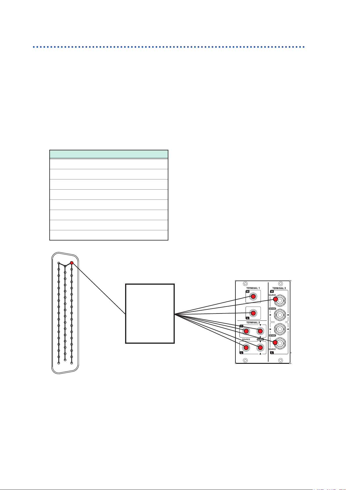
Check that the terminals of the shorted modules and the following points of the terminals on
3
the main frame are not electrically connected.
Continuity inspection points
TERMINAL 1, H
TERMINAL 1, L
TERMINAL 2, SENSE H
TERMINAL 2, SENSE L
TERMINAL 2, SOURCE H
TERMINAL 2, SOURCE L
TERMINAL 3, SOURCE H shield
TERMINAL 3, SOURCE L shield
17
1
33
18
The connector is for the SW9001.
50
Check that the terminal of the shorted
module and the above points of the
34
terminal on the main frame are not
electrically connected.
Tester
Send inspection command: TEST:RELAYSHORT <No. of slot to be inspected>,BUS, and set the
4
test state of the bus relay, then conrm step 3.
Send inspection command: TEST:RELAYSHORT <No. of slot to be inspected>,OPEN, and end the
5
inspection for this slot.
Perform steps 1 to 5 for all the slots.
6
Module relay contact may be weld if it was conducted during inspection. Stop the use and contact
your authorized Hioki distributor or reseller.
26
Page 31

Overview of Channel Switching
3.2 Overview of Channel Switching
This device connects to the internal analog bus by switching the relay of each module channel. The
internal analog bus is connected to the terminal for connecting the instrument.
The device is all controlled by communication commands. For details about the command, refer to
the description of each item.
TERMINAL 1
2-terminal banana
Sense
H
L
GND
terminal
TERMINAL 2
4-terminal banana
Sense
H
L
H
L
TERMINAL 3
BNC
Sense
Sense shield
SourceSource
H
L
Source shield
Bus relay
Internal analog bus
3
Channel Switching
Channel relay
Sense
channel
Source
channel
Return
channel
Shield wire
Module
• The sense shield for TERMINAL 3 (BNC terminal) is common (short circuit) for H and L.
• The diagram for wire connection inside the module is conceptual and differs from the actual
module connection. See the wiring diagram for each module.
Reference: Switching wiring diagram (p. 132, p. 138)
Select the channel to be measured using the channel relay and specify the terminal to which
the channel is to be connected (select the connection method) using the bus relay. The selected
channel can be measured using an instrument.
The sense and source for TERMINAL 2 (4-terminal banana terminal) and TERMINAL 3 (BNC
terminal) use a common analog bus (electrically connected).
CAUTION
Do not connect TERMINAL 2 and TERMINAL 3 to the instrument at the same time.
Doing so may damage the instrument.
27
Page 32

Procedure for Switching the Channel
3.3 Procedure for Switching the Channel
Switch the channel according to the following setting and procedure.
• Selecting the connection method
• Switching the shield
• Selecting the channel
Selecting the connection method
The connection method can be selected for each slot. Selecting the connection method determines
the terminal of the connection destination (instrument).
Module
SW9001
SW9002
SW9001 4-wire Battery tester BT3562 TERMINAL 2 L2108
SW9002 4-terminal pair
Connection
method
2-wire Voltmeter DM7276 TERMINAL 1 L4930
Instrument
example
Battery tester BT4560
LCR meter IM3590
Model Terminal
Connection
cable
TERMINAL 3 L2004
Once the connection method is specied, it is retained. You do not have to specify the connection
method every time the channel is switched.
Once the connection method is specied, all the channels become open. The shield wire is
connected to the specied connection destination for each connection method. If you wish to switch
a channel to another terminal, specify the connection method and then close the channel.
The number of channels that can be used varies depending on the module type and connection
method as shown below.
Module
SW9001
Connection
method
2-wire 22 Sense CH1 to CH22 TERMINAL 1
4-wire 11
Number of
channels
Signal type Signal to be used
Source CH1 to CH11
Sense CH12 to CH22
Terminal to be
used
TERMINAL 2
2-wire 6 Sense Sense: CH1 to CH6 TERMINAL 1
SW9002
4-terminal pair 6
If the SW9001 is set to 4-wire and the 4-
in pairs.
Source: CH n
Sense: CH (n+11)
Item Communication command
Setting
procedure
Setting
example
:SYSTem:MODule:WIRE:MODE <
Set SLOT 1 to 2-wire.
:SYST:MOD:WIRE:MODE 1,WIRE2
Set SLOT 5 to 4-terminal pair.
:SYST:MOD:WIRE:MODE 5,TP4
28
Source Source: CH1 to CH6
TERMINAL 3Return Return: CH1 to CH6
Sense Sense: CH1 to CH6
wire
selection channel is “n”, the following signals are used
slot number
>,<WIRE2/WIRE4/TP4>
Page 33

Procedure for Switching the Channel
Switching the shield
When the connection method is selected, the shield wire is connected to the specied connection
destination.
Specied shield switching setting (shielding connection destination)
Module Connection method Shield connection destination
SW9001
2-wire TERMINAL 1, LOW terminal
4-wire GND
SW9002
2-wire TERMINAL 1, LOW terminal
4-terminal pair TERMINAL 3, sense shield terminal
The destination for shielding connection can be switched as necessary (for each slot).
Any time the connection method for a slot is changed, the switching shield will be reset to the
specied value. To set the switching shield to a value other than the specied value, be sure to set
the switching shield after setting the connection method.
Destination for shield wire connection to be selected
Module Connection destination terminal
Not connected
GND
TERMINAL 1, LOW terminal
SW9001
TERMINAL 2,TERMINAL 3, source LOW terminal
TERMINAL 3, sense shield terminal
TERMINAL 1, LOW terminal + TERMINAL 3, sense shield terminal
Not connected
GND
SW9002
TERMINAL 1, LOW terminal
3
Channel Switching
TERMINAL 3, sense shield terminal
For the SW9001, the [TERMINAL 1, LOW terminal + TERMINAL 3, sense shield terminal] shielding
connection destination terminal should only be used when connecting a BT3562 and DM7275/DM7276
at the same time when the DM7275/DM7276 contact check function is not operating properly.
Once the connection destination is specied, it is retained until the connection method is changed.
You do not have to specify the connection destination every time the channel is switched.
When the switching shield is set, all channels are set to open.
The source terminal for TERMINAL 2 and sense terminal are common for TERMINAL 3.
Item Communication command
Setting
procedure
Setting
example
:SYSTem:MODule:SHIeld <
TERMinal3/T1T3>
Set the shield wire connection destination for SLOT 1 to GND.
:SYST:MOD:SHI 1,GND
Set the shield wire connection destination for SLOT 5 to “not connected”.
:SYST:MOD:SHI 5,OFF
slot No.
>,<OFF/GND/TERMinal1/TERMinal2/
29
Page 34

Procedure for Switching the Channel
Selecting the channel
Select the slot and channel No.
When the channel is selected, the specied slot of channel relay is closed, as well as the bus relay
is also closed due to the connection method.
Item Communication command
Setting
procedure
[ROUTe]: CLOSe <
<
Slot and channel No.
Slot and channel No.
> =
Slot No. × 100 + CH No.
>
Setting
example
Item Communication command
Setting
procedure
Setting
example
Select CH7 of SLOT 1.
:CLOS 107
Select CH22 of SLOT 12.
:CLOS 1222
[:ROUTe]:OPEN
Open all channels.
:OPEN
Restriction
Multiple channels cannot be closed simultaneously.
Waiting for channel selection (switching) to complete
Switching operation is triggered by the channel selection command.
You can verify whether channel switching operation has completed by receiving the next query
response. The switching operation time is included in the channel delay time.
See: "3.7 Channel Delay Function" (p. 37)
Waiting for channel switching operation to complete
Item Communication command
Conrming
procedure
Conrming
example
OPC
∗
Response:
Waits for the present operation to complete and returns the value 1.
The subsequent command will be made to wait until this command completes.
Select CH7 of SLOT 1 and wait for switching operation to complete.
:CLOS 107
OPC?
∗
1
(receive a response = switching operation complete)
1
30
Page 35

Channel Switching Operation
3.4 Channel Switching Operation
When the channel is selected (closed), channel switching is performed according to the following
ow.
Channel switching
Enabled channel Previous channel Selected channel
Relay operation Close Open Close
Operation
standby time
EXT. I/O CLOSE ON OFF ON
If the next channel is closed before the CLOSE signal pulse reaches the set pulse width, CLOSE
signal pulse will automatically turn off.
After the previous channel relay is opened, the selected channel relay is closed (break before
make).
Channel switching cannot be overlapped (make before break).
In channel switching within the same slot, the bus relay is not opened and only the channel relay is
switched.
If the channel for a different slot is selected, the bus relay and channel relay of the previous slot are
opened and the bus relay and channel relay of the selected slot are closed.
After the channel relay is closed and then the settling time that is automatically set and the channel
delay time that is specied by the customer elapse, channel switching operation is complete and
the CLOSE output signal of EXT. I/O is turned on (pulse output at the set pulse width).
Settling time
Channel
delay
Set pulse
width
3
Channel Switching
31
Page 36

Measurement between Two Instruments
3.5 Measurement between Two Instruments
Changing the connection method enables measurement to be performed by switching between two
instruments according to the application.
Example: Measure the internal resistance of 8 batteries using BT3562 and measure the OCV using
DM7276. (Use SLOT 1, 4-wire, CH1 to CH8.)
Connect BT3562 to TERMINAL 2 and DM7276 to TERMINAL 1.
1
Instrument
BT3562
DM7276 OCV SW9001 2-wire
Set the connection method of SLOT 1 to 4-wire.
2
The signal is connected to TERMINAL 2.
Repeat channel selection and measurement using BT3562 for 8 channels (internal resistance
3
measurement).
Measurement
item
Internal
resistance
Module
SW9001 4-wire
Connection
method
Channel selection Terminal to be used
SLOT 1, CH1
SLOT 1, CH2
SLOT 1, CH3
⁞
SLOT 1, CH8
SLOT 1, CH12
SLOT 1, CH13
SLOT 1, CH14
⁞
SLOT 1, CH19
TERMINAL 2
TERMINAL 1
Set the connection method to 2-wire.
4
The signal is connected to TERMINAL 1.
Repeat channel selection and measurement using DM7276 in the same way as for internal
5
resistance measurement (OCV measurement).
The sense wire for 4-wire CH1 to CH8 corresponds to 2-wire CH12 to CH19.
32
Page 37

Control example using communication command
[SW1001] :SYST:MOD:WIRE:MODE 1,WIRE4
[SW1001] :CLOSE 101
[SW1001] ∗OPC?
[SW1001] 1
[BT3562] :READ?
[BT3562] 1.0258E-3
[SW1001] :CLOSE 102
...
[SW1001] :SYST:MOD:WIRE:MODE 1,WIRE2
[SW1001] :CLOSE 112
[SW1001] ∗OPC?
[SW1001] 1
[DM7276] :READ?
[DM7276] +03.764987E+00
[SW1001] :CLOSE 113
...
Measurement between Two Instruments
Set the SLOT 1 connection method to 4-wire (connect to
TERMINAL 2).
Select SLOT 1, CH1.
Check that the channel relay has been closed.
OPC?
Receive a response “1” to the
Execute single measurement using BT3562.
Receive measured values.
Select the next CH2.
(Repeat until CH8.)
Set the SLOT 1 connection method to 2-wire (connect to
TERMINAL 1).
Select SLOT1, CH12 (4-wire CH1 sense).
Check that the channel relay has been closed.
Receive a response “1” to the
Execute single measurement using DM7276.
Receive measured values.
Select the next CH13 (4-wire CH2 sense).
(Repeat until CH19.)
∗
OPC?
∗
query.
query.
3
Channel Switching
Example: Measure the internal resistance of 8 batteries using BT3562 and measure the OCV using
DM7276. Then measure the external potential for batteries using the DM7276.
(Use SLOT 1, 4-wire, CH1 to CH8 for internal resistance and OCV measurement.
Use SLOT 2, 2-wire, CH1 to CH8 for external potential measurement for batteries.)
Connect BT3562 to TERMINAL 2 and DM7276 to TERMINAL 1.
1
Instrument Measurement item Module
BT3562 Internal resistance SW9001 4-wire
DM7276 OCV SW9001 2-wire
Connection
method
Channel selection Terminal to be used
SLOT 1, CH1
SLOT 1, CH2
SLOT 1, CH3
⁞
SLOT 1, CH8
SLOT 1, CH12
SLOT 1, CH13
SLOT 1, CH14
⁞
SLOT 1, CH19
TERMINAL 2
TERMINAL 1
External potential
DM7276
Set the connection method of SLOT 1 to 4-wire.
2
The signal is connected to TERMINAL 2.
measurement for
batteries
SW9001 2-wire
SLOT 2, CH1
SLOT 2, CH2
SLOT 2, CH3
⁞
SLOT 2, CH8
TERMINAL 1
33
Page 38

Measurement between Two Instruments
Repeat channel selection and measurement using BT3562 for 8 channels (internal resistance
3
measurement).
Set the connection method to 2-wire.
4
The signal is connected to TERMINAL 1.
Repeat channel selection and measurement using DM7276 in the same way as for internal
5
resistance measurement (OCV measurement).
The sense wire for 4-wire CH1 to CH8 corresponds to 2-wire CH12 to CH19.
Set the connection method of SLOT 2 to 2-wire.
6
Use SLOT 2 for external potential for batteries since the measurement points are different.
The signal is connected to TERMINAL 1.
Repeat channel selection and measurement using DM7276 (external potential measurement
7
for batteries).
Control example using communication command
[SW1001] :SYST:MOD:WIRE:MODE 1,WIRE4
[SW1001] :CLOSE 101
[SW1001] ∗OPC?
[SW1001] 1
[BT3562] :READ?
[BT3562] 1.0258E-3
[SW1001] :CLOSE 102
...
[SW1001] :SYST:MOD:WIRE:MODE 1,WIRE2
[SW1001] :CLOSE 112
[SW1001] ∗OPC?
[SW1001] 1
[DM7276] :READ?
[DM7276] +03.764987E+00
[SW1001] :CLOSE 113
...
[SW1001] :SYST:MOD:WIRE:MODE 2,WIRE2
[SW1001] :CLOSE 201
[SW1001] ∗OPC?
[SW1001] 1
[DM7276] :READ?
[DM7276] +00.257139E+00
[SW1001] :CLOSE 202
...
Set SLOT 1 to 4-wire (connect to TERMINAL 2).
Select SLOT 1, CH1.
Check that the channel relay has been closed.
OPC?
Receive a response “1” to the
Execute single measurement using BT3562.
Receive measured values.
Select the next CH2.
(Repeat until CH8.)
Set SLOT 1 to 2-wire (connect to TERMINAL 1).
Select SLOT 1, CH12 (4-wire CH1 sense).
Check that the channel relay has been closed.
Receive a response “1” to the
Execute single measurement using DM7276.
Receive measured values.
Select the next CH13 (4-wire CH2 sense).
(Repeat until CH19.)
Set SLOT 2 to 2-wire (connect to TERMINAL 1).
Select SLOT 2, CH1.
Check that the channel relay has been closed.
Receive a response “1” to the
Execute single measurement using DM7276.
Receive measured values.
Select the next CH2.
(Repeat until CH8.)
∗
OPC?
∗
OPC?
∗
query.
query.
query.
34
Page 39

Precautions for Measurement
3.6 Precautions for Measurement
Use in combination with BT3562 or BT3563
Contact check does not operate properly at 3000 Ω range. Also be aware that contact check cannot
be performed properly in the voltage function, either.
Use in combination with BT4560
Use the device with BT4560 for external trigger measurement or single measurement using the
:READ?
When using the device for internal trigger (free running), the life time of the relay is shortened as
the channel is switched during measurement (hot switching).
As the measurement current for BT4560 is 1.5 A (3 mΩ range), heat generation at the relay contact
becomes high. With heat generation, the thermoelectric power may become high.
command.
3
Use in combination with DM7275 or DM7276
If a measurement accuracy of a few µV is required, there is an effect by the thermoelectric power
due to coil heating of the channel relay. Minimize the close time of each channel to reduce this
effect as much as possible. Use single measurement using the
trigger and open the channel immediately after the measurement (heating from the relay coil is
controlled).
Measured value variation may be signicant when connected at the same time as the IM3590.
If you encounter this issue, enable the IM3590’s trigger synchronous output function.
:READ?
command or external
Use in combination with IM3590
Execute open correction and short correction to each channel you will use.
Error might occur to open correction and short correction due to high frequency. (Set the frequency
range you will correct when executing.)
Threshold value of the contact check might be larger than the setting.
Also, the inspection result of the contact state (the resistance value near the threshold) might vary.
Relay operation time and stability time
The relay open/close operation waits for a contact operation time (settling time). The settling time is
as follows.
Channel switching time
Channel Switching
Relay open settling time Relay close settling time
Settling time
Relay open Relay close Channel switching
5 ms 5 ms 11 ms
The relay contact operation is completed within the settling time, however, it may take some time
for the relay to be stabilized depending on the instrument to be used or measuring object. Set the
channel delay time or perform measurement after a sufcient delay time on the instrument.
Preventing relay contact welding
The relay contact may weld when relay switching is repeated with a large current owing (also
when the measuring object or instrument to be connected is capacitive). When relay contact
welding occurs, the measuring object may be shorted. Periodic inspection is recommended.
Reference: "Checking for relay contact welding" (p. 26)
35
Page 40

Precautions for Measurement
Inuence of thermoelectric power
Be aware of the thermoelectric power when a voltage accuracy of a few µV is required.
Install the device and instrument in a constant temperature environment and fully adjust them to the
ambient temperature before use.
Especially prevent uneven temperatures at the terminal.
When creating a measurement cable, use a connector and terminal of a material with low
thermoelectric voltage, such as brass (nickel plate), pure copper (+ gold plate), etc.
Exercise care to keep the contact surface clean.
High resistance and minute current measurement
In a high humidity environment, high resistance or minute current measurement may be affected by
leak current.
Do not touch the module board with your bare hand. Grease can cause leak current, which may
affect high resistance and minute current measurement.
Do not bundle the measurement cables when measuring minute current. Doing so may cause leak
current due to the capacity of the cables, resulting in an error in the measured value.
Caution regarding noise
Do not bundle the measurement cables or connection cables for the instrument and the power line.
Noise on the power line may cause malfunction of channel switching or an error in the measured
value.
When the measured value cannot be stabilized due to noise, connecting the ground (GND terminal)
of the device and the ground of the instrument may improve the condition.
Caution regarding load
When a load is applied to the measurement cable, the contact area of the connector becomes
unstable and the contact resistance is increased, which can cause the measured value to be
unstable.
When attaching the module to the main frame, be sure to secure the panel using screws. If the
panel cannot support the load when a vertical load is applied to the main frame, the module board
is stressed and may malfunction.
36
Page 41

Channel Delay Function
3.7 Channel Delay Function
The delay time after channel switching can be specied. When the specied delay time elapses
after the channel relay is closed, a CLOSE signal of EXT. I/O is output.
If the measurement response time for the instrument needs to be ensured, set the delay time.
The required delay time depends on the instrument to be used and the measuring object.
Channel delay time setting example
Model Delay time
BT4560 1 ms
BT3562 10 ms
3561 3 ms
DM7276 0 ms
The channel delay time can be specied for each slot. The same delay time is used for all channels
within the slot.
For the switching sequence, see "3.4 Channel Switching Operation" (p. 31)
Item Communication command
Setting
procedure
Setting
example
:SYSTem:MODule:DELay <
Set the channel delay time for SLOT 1 to 0.01 sec. and for SLOT 2 to 0 sec.
:SYST:MOD:DEL 1,0.01
:SYST:MOD:DEL 2,0
slot No.
>,<
delay time 0 to
9.999[s]>
3
Channel Switching
37
Page 42

Precautions for Measurement
38
Page 43

4
Scan Function
Thoroughly read "Usage Notes" (p. 4) beforehand.
4.1 Overview of the Scan Function
For scanning, specify the channel range (scan list) in advance and switch the channel in order.
Channel switching (scan channel moving forward) can be performed using EXT. I/O or
communications. Connecting the switch mainframe and the instrument EXT. I/O can switch the
channel and perform measurement in synchronization with the instrument.
This device
CH 1
↓
CH 2
↓
⁞
The channel is switched every time the signal is input.
Scanning in combination with the instrument
This device
CH 1
↓
CH 2
↓
⁞
Channel switching and external trigger measurement
synchronized for automatic execution
CLOSE output signal
SCAN input signal
EXT. I/O SCAN signal
or
TRG
command
*
TRIG input
Instrument
External trigger
measurement executed
EOM output
EOM = Measurement completion signal
Set the instrument to the external trigger
mode.
4
Scan Function
Precautions when performing a scan when the device and instrument are connected via EXT. I/O
• Only one instrument can be used.
• Use either the instrument’s data output function or its memory function to acquire measured
values from the scan. For more information, please see the instrument’s instruction manual.
• The EOM signal from the instrument may cause scan measurement to resume even if it has been
stopped using the SCAN_RESET signal or the
For the EXT. I/O signal, see "Signal Functions" (p. 52).
:ABORt
command.
39
Page 44

Setting the Scan Channel
4.2 Setting the Scan Channel
The channels to be scanned need to be registered as a scan list.
Specify the start and end channels. An individual channel list can also be specied.
Item Communication command
Setting
procedure
[:ROUTe]:SCAN<(@
<(@
Channel list
Channel list format
<CH>,<CH>,...,<CH>
<CHm>:<CHn>
Channel list
)>
)>
Specify the channels to be measured individually.
Specify from CHm to CHn consecutively.
Setting
example
Scan CH1 of SLOT 1 to CH22 of SLOT 3.
:SCAN 101:322
Scan CH1 and CH2 of SLOT 1 and CH1, CH2, and CH5 of SLOT 2.
:SCAN (@101,102,201,202,205)
4.3 Setting the Trigger Source for Scan Operation
A trigger source for scan operation is set for STEP only.
Trigger source Scan operation
STEP Scanning is started by the SCAN input signal or
closed). Then the next scan channel is scanned every time the SCAN input signal or
TRG
command is sent.
*
STEP is set as the default setting. Normally select STEP and execute scanning while
synchronizing with control of the instrument.
The commands to be set are as follows.
Item Communication command
Setting
procedure
:TRIGger:SOURce <STEP>
<STEP>
TRG
command (the rst channel is
*
40
Setting
example
STEP:
External trigger. Scanning is performed with the SCAN input signal of EXT. I/O or the
command. Scan operation moves along the steps every time the trigger is input.
Set to proceed with the next step every time the external trigger is input.
:TRIG:SOUR STEP
*
TRG
Page 45

4.4 Scan Operation
Scan Operation
Scanning is started by the SCAN signal of EXT. I/O or the communication
channel is moved forward by the SCAN signal or the
*
TRG
command.
When the channel is the nal channel, scanning is completed by the SCAN signal or the
TRG
command. The scan
*
*
TRG
command,
and all relay is opened and goes back to the beginning of the scan list. Note that scan operation will not
complete until another SCAN signal or
TRG
command is input in the nal channel state.
*
Scan operation when the trigger source is set to STEP
SCAN signal or
TRG
command
*
Channel Open
CLOSE signal OFF ON
Start
channel
Open
Next
channel
…
Open
The CLOSE signal is output in pulses. The pulse width can be set using the following command
IO:PULSe:TIME <0.001
0.100/MIN/MAX/DEF>
to
. (See p. 102.)
If the next channel is closed before the CLOSE signal pulse reaches the set pulse width, CLOSE
signal pulse will automatically turn off.
Item Communication command
Setting
procedure
Setting
example
TRG
*
:ABORt
Executes scanning twice from CH1 of SLOT 1 to CH22 of SLOT 3.
:SCAN 101:322
:TRIG:SOUR STEP
TRG
*
TRG
*
Scanning is performed again after completion.
TRG
*
TRG
*
Starts scanning and proceeds along the scan channels.
Aborts scan operation and returns to the beginning of the scan
channel.
Advances the scan channel one step at a time using the
command (or SCAN signal).
(Repeats for the number of channels.)
Scan operation complete by nal channel state.
(Repeats for the number of channels.)
Scan operation complete by nal channel state.
Final
channel
Scan complete
Open
TRG
*
:
4
Scan Function
Aborts scan operation and restarts from the beginning.
:SCAN 101:322
:TRIG:SOUR STEP
TRG
*
:ABOR
TRG
*
Advances the scan channel one step at a time using the
command (or SCAN signal).
(Repeats.)
(Aborts scan operation and returns to the beginning of the scan
channel.)
(Repeats for the number of channels from the rst channel.)
All channels are open after scanning is stopped.
The following commands are disabled during scanning.
• Setting the connection method
• Setting the shield switching
• Channel switching
• Setting the channel delay
• Setting the scan list
• Setting concerning the EXT. I/O
• Channel control due to CLOSE command
TRG
*
41
Page 46

Resetting Scan Operation
4.5 Resetting Scan Operation
Scanning is reset and stopped by the SCAN_RESET signal of EXT. I/O or the communication
:ABORt
command. All channel relays are opened and goes back to the beginning of the scan list.
42
Page 47

Scan Measurement Example
4.6 Scan Measurement Example
The following example shows scan measurement with the SW1001 and BT3562 connected using
EXT. I/O.
For acquiring measured values, the BT3562 data output function is used.
Scan measurement start
BT3562 setting
External trigger
Set data output to on
SW1001 setting
Connection method: 4-wire
Scan list registration
SW1001
Start scanning
Scan input signal or
command
*
TRG
PC
USB
SW1001
CLOSE
SCAN
TRIG
EOM
RS-232C
BT3562
4
Scan Function
Wiring diagram
No
BT3562
Receive measured values.
Measured value
received for all
channels
Yes
Scan measurement
complete
43
Page 48

Resetting Scan Operation
44
Page 49

5
Other Functions
5.1 Checking the Device Status
The following items can be checked using the free software for the SW1001 series (downloaded
from our website).
• Module information of each slot
Slot position, model, serial number, and opening/closing frequency of each relay
Use the information as a reference for the relay lifetime.
5
Other Functions
45
Page 50

Checking the Device Status
46
Page 51

6
Initialization
6.1 Initialization Settings
The device is in the initial state at the time of shipment and at the time of initialization using
commands. However, communications settings will not be initialized if the initialization is triggered
by command.
Settings that are backed up can be stored so that they persist even when the power is turned off by
executing the
See: “Backing up settings” (p. 105)
Communications settings are backed up even if the
Channel relay All relays open –
Bus relay All relays open –
EXT. I/O CLOSE output signal OFF –
:SYSTem:BACKup
Item Initialization description Backup
command.
:SYSTem:BACKup
command is not executed.
: Yes, –: No
Connection method
Shield switching
Channel delay settings 0.0 s
Scan list None
Scan operation trigger source STEP
Query forwarding timeout 10 s
EXT. I/O lter function OFF, 0.05 s
Pulse width of CLOSE output
signal
Communication settings (USB) (No setting item) –
Communication settings
(RS-232C)
Communication settings (LAN)
SW9001: 2-wire
SW9002: 4-terminal pair
SW9001: TERMINAL 1, LOW terminal
SW9002: TERMINAL 3, sense shield terminal
0.005 s
9600 bps
User setting mode (setting switch: USER)
IP address: 192.168.0.254
Subnet mask: 255.255.255.0
Default gateway: 0.0.0.0 (None)
Communication command port number: 23
Fixed setting mode (setting switch: DFLT)
6
Initialization
IP address: 192.168.0.254
Subnet mask: 255.255.255.0
Default gateway: 0.0.0.0 (None)
Communication command port number: 23
–
47
Page 52

Initialization Settings
48
Page 53

7
External Control (EXT. I/O)
Thoroughly read “Before starting the external control” (p. 6) beforehand.
Connecting the instrument and the EXT. I/O terminal allows you to perform measurement in
synchronization with channel switching when using the scan function. Also scan control can be
performed from the PLC and other devices.
All signals are isolated from the switching circuit, communication circuit, and ground (earth) (the
common terminal for I/O is shared).
The input circuit can be switched so that it can support sinking current output (NPN) or sourcing
current output (PNP).
Check the input/output rating and internal circuit conguration, and then understand the safety
precautions. After that, connect the instrument or control system and use it in a correct manner.
Rear
Signal output or input
7.1 External Control Flow
Check the I/O specications of the instrument and external device to be connected.
Setting NPN/PNP in the device (p. 50).
Connecting the device and the external device (p. 51).
7
External Control (EXT. I/O)
49
Page 54

Switching between Sinking Current (NPN) and Sourcing Current (PNP)
7.2 Switching between Sinking Current (NPN) and Sourcing Current (PNP)
Thoroughly read “Before starting the external control” (p. 6) beforehand.
The applicable PLC type can be changed using the EXT. I/O MODE change-over switch. It is set to
NPN at the time of shipment.
EXT. I/O MODE change-over switch settings
NPN PNP
Device input circuit Supports sinking output. Supports sourcing output.
Device output circuit Non-polar Non-polar
Rear
ISO_5 V output +5 V output
Left: Sinking current (NPN)
Right: Sourcing current (PNP)
-
5 V output
50
Page 55

7.3 Connection
Device connector and compatible connectors
Thoroughly read “Before starting the external control” (p. 6) beforehand.
Rear
5 4 3 2 1
9 8 7 6
Connectors used (device unit side)
• D-SUB 9-pin
Female #4-40 inch screw
Connection
Compatible connectors
• DE-9P-ULR (solder type)
• DESP-JB9PR (crimping type)
Manufactured by Japan Aviation Electronics Industry, Limited
The connector frame is connected to the casing (metal) of the device as well as the protective
ground terminal of the power inlet (conductive). Be aware that it is not isolated from the ground.
Pin Signal name I/O Function Logic
1 SCAN IN Scan start/advance Edge
2 (Reserved) IN – –
3 ISO_5V – Isolated power supply +5 V (−5 V) output –
4 CLOSE OUT Channel closing complete Pulse
5 (Reserved) OUT – –
6 SCAN_RESET IN Resets scan operation. Edge
7 (Reserved) IN – –
8 ISO_COM – Isolated power supply common –
9 (Reserved) OUT – –
7
External Control (EXT. I/O)
51
Page 56

Connection
Signal Functions
Isolated power supply output
Pin Signal name
3 ISO_5V Isolated power supply +5 V Isolated power supply −5 V output
8 ISO_COM Isolated power supply common Isolated power supply common
Input signal
Signal name Description Reference
SCAN
SCAN_RESET
Output signal
Signal name Description Reference
CLOSE
EXT. I/O MODE change-over switch settings
NPN PNP
Starts scan operation.
Moves forward to the next channel during scan operation.
This signal is not valid when switching channels (until the CLOSE signal is
output).
Resets scan operation and stops scanning.
All channel relays are opened.
Outputs a pulse signal with the set pulse width when the channel relay is
closed.
The signal will turn off when the set pulse width time elapses or when the
channel relay opens.
p. 41
p. 42
p. 31
Connection to the instrument
An example of connecting the device and instrument for scan measurement is shown below.
Example: Connecting the BT3562 Battery HiTester
Set the BT3562 to the external trigger mode.
SW1001 (SW1002)
Rear
5 4 3 2 1
9 8 7 6
4: CLOSE
1: SCAN
8: ISO_COM
BT3562
Rear
1: TRIG
28: EOM
27: ISO_COM
52
9 8 7 6 5 4 3 2 1
10
1112131617 14151819
282930313435 32333637 20212425 22232627
Page 57

7.4 Timing Chart
The level of each signal shows the contact on/off status.
In the sourcing current (PNP) setting, HIGH and LOW in the timing chart are the same as the
voltage level of the EXT. I/O terminal. HIGH and LOW are reversed for the voltage level in the
sinking current (NPN) setting.
Channel switching operation and scan operation reset
(1) Channel switching operation
The scan input signal starts scanning and advances the scan channel.
Timing Chart
SCAN
Enabled channel
Relay operation
Operation
standby time
CLOSE
If the next channel is closed before the CLOSE signal pulse reaches the set pulse width, CLOSE
signal pulse will automatically turn off.
The SCAN input signal is not valid while switching channels (until the CLOSE signal is output).
Previous channel
ON OFF ON
Close Open Close
ON
ON
T1
Settling time
T2
Channel switching
Selected channel
Channel delay
T3 T4
ON
T5
7
External Control (EXT. I/O)
53
Page 58

Timing Chart
(2) Scan operation reset
When the SCAN_RESET signal is input during scan operation, the scan operation is stopped and
the channel relay is opened. When the scan signal is input with the scan operation reset, the scan
operation is restarted from the beginning.
SCAN
SCAN_RESET
Scan channel
CLOSE
Item Description Time
T1 SCAN signal pulse width 1 ms or longer
T2 Relay settling time (when it is opened) SW9001: 5 ms, SW9002: 5 ms
T3 Relay settling time (when it is closed) SW9001: 5 ms, SW9002: 5 ms
T4 Channel delay time (user setting) 0 ms to 9999 ms (based on the setting)
T5 CLOSE signal pulse width 1 ms to 100 ms
Channel n Channel n+1 Channel n+2
ON OFF
ON
Open Open
OFF
As per the
OFF
:IO:PULSe:TIME
command setting
ON
T6
OFF
Open
Scan stop
T6 SCAN_RESET signal pulse width 1 ms or longer
54
Page 59

7.5 Internal Circuit Conguration
NPN setting
Do not connect external power to one pin.
This device
3
ISO_5 V
2 k
Ω
1 k
EXT. I/O MODE
selector
NPN
5 V
Ω
Internal isolated
power supply
10
Ω
1
SCAN
6
SCAN_RESET
4
CLOSE
Internal Circuit Conguration
PLC, etc.
Output
Common
PLC, etc.
Input
Zener voltage 30 V
8
Internal isolated common
(It is isolated from the ground for the device.)
ISO_COM
Common
30 V max.
7
External Control (EXT. I/O)
55
Page 60

Internal Circuit Conguration
PNP setting
Use ISO_COM for the common terminal for both the input and output signals.
Do not connect external power to one pin.
This device
3
ISO_5 V
2 k
Ω
1 k
Ω
1
SCAN
6
SCAN_RESET
PLC, etc.
Output
5 V
EXT. I/O MODE
selector
PNP
10
Ω
Zener voltage 30 V
Internal isolated common
(It is isolated from the ground for the device.)
Electrical specications
Input signal Input format Isolated non-voltage contact input using a photocoupler
Internal isolated
power supply
(Compatible with sinking/sourcing current output)
4
8
CLOSE
ISO_COM
Common
PLC, etc.
Input
Common
30 V max.
56
Input ON Residual voltage 1 V (input ON current 4 mA (reference value))
Input OFF OPEN (interrupting current 100 µA or less)
Output signal Output format Isolated open drain output using a photocoupler (non-polar)
Maximum load voltage 30 V DC max.
Maximum output current 50 mA/channel
Residual voltage 1 V or less (load current 50 mA)/0.5 V or less (load current 10
mA)
Internal
isolated power
supply
Output voltage Sinking output compatible: +4.2 V to +5.8 V
Sourcing output compatible:
Maximum output current 100 mA
External power supply
input
Insulation Floating from the protective grounded potential and the
Insulation rating Voltage between the module and ground: 50 V DC, 30 V AC
None
measurement circuit
rms, 42.4 V AC peak or less
-
4.2 V to -5.8 V
Page 61

Connection examples
Input circuit connection examples
This device This device
Internal Circuit Conguration
Input
NPN
ISO_COM
Connection to the switch Connection to the relay
This device This device
Input Input
NPN PNP
ISO_COM
Connection to the PLC output (NPN output) Connection to the PLC output (PNP output)
Common
NPN
Input
ISO_COM
ISO_COM
PLC
OutputOutput
Common
7
External Control (EXT. I/O)
57
Page 62

Internal Circuit Conguration
Output circuit connection examples
This device
Output Output
50 mA max. 50 mA max.
ISO_COM
30 V max.
This device
ISO_COM
Connection to the relay Connection to the LED
This device
This device
Output
50 mA max.
ISO_COM
Negative-true
logic output
Negative-true logic output
Output
Output
ISO_COM
Wired-OR
This device
Output
PLC
Input
This device
Output
PLC
Input
50 mA max.
ISO_COM
Common
Connection to the PLC input
(plus common input)
50 mA max.
ISO_COM Common
Connection to the PLC input
(minus common input)
58
Page 63

8
Communication Function
8.1 Interface Overview and Features
The device can be controlled using the LAN interface, USB interface, or RS-232-C interface.
All of the interfaces can be used and do not need to be specied. To avoid malfunction, however,
use only one interface for control.
For the specications, see "9.4 SW1001, SW1002 Interface Specications" (p. 123).
8.2 Setting the Communication Setting Mode
The communication setting mode needs to be specied before using the communication function.
Communication settings can be specied for each interface to be used, however, the
communication setting mode should be selected if the present communication settings are
unknown.
Fixed setting mode (DFLT)
User setting mode (USER)
The device is in the xed setting mode at the time of shipment.
Refer to "2.6 Setting the Communication Setting Mode" (p. 22) to set the communication setting
mode.
Specify communication settings according to the interface to be used.
See:
"8.3 LAN Interface" (p. 60)
"8.4 USB Interface" (p. 64)
"8.5 RS-232C Interface" (p. 66)
Communications are performed using the specied
communication settings.
Communications are performed with the user-specied
communication settings.
8
Communication Function
59
Page 64

LAN Interface
8.3 LAN Interface
This device is equipped with an Ethernet 100BASE-TX interface as standard. The device
is connected to the network using a LAN cable (up to 100 m) compatible with 10BASE-T or
100BASE-TX, and then the device can be controlled using the PC.
Networking the device and PC Perform one-to-one connection
between the device and PC.
Hub
Hub
When a program is created and the device is connected to the communication command port via
TCP, the device can be controlled using communication commands.
Flow of preparations
Set the communication conditions of the device (p. 61).
Connect the LAN cable (p. 63).
60
Page 65

Communication condition settings
To be checked before setting
The settings are different when the device and external device are connected to the existing
network and when the device and a PC are connected to a new network.
Connecting the device to the existing network
The network administrator (department) needs to assign the following items in advance. Be sure to
assign them so that they do not overlap with other devices.
• Address settings of the device
IP address: ................................................................. ___.___.___.___
Subnet mask: ............................................................. ___.___.___.___
• Gateway
Whether or not to use a gateway: .............................. Use / Not use
IP address (if used): ................................................... ___.___.___.___
(Set to 0.0.0.0 if not used)
LAN Interface
• Communication command port No. to be used: ___ (Default setting: 23)
Creating a new network using the device and a PC
(Using a local network that is not connected externally)
The addresses shown below are recommended if there is no administrator or you are responsible
for setting.
Setting example:
IP address Set sequential IP addresses as shown below.
PC: 192.168.0.1
First device: 192.168.0.2
Second device: 192.168.0.3
Third device: 192.168.0.4
↓
Subnet mask: 255.255.255.0
Gateway: OFF
Communication command port number: 23
8
Communication Function
61
Page 66

LAN Interface
Setting LAN communications
Set the commands shown below for the LAN communications.
:SYSTem:COMMunicate:LAN:IPADdress <Value 1>,<Value 2>,<Value 3>,<Value 4>
Set the IP address for the device.
:SYSTem:COMMunicate:LAN:SMASK <Value 1>,<Value 2>,<Value 3>,<Value 4>
Set the LAN subnet mask.
:SYSTem:COMMunicate:LAN:GATeway <Value 1>,<Value 2>,<Value 3>,<Value 4>
Set the address for the default gateway.
:SYSTem:COMMunicate:LAN:CONTrol <1 - 9999>
Specify the communication command port No.
:SYSTem:COMMunicate:LAN:UPDate
Update and apply the LAN settings.
When the communication setting mode switch (DFLT/USER) is set to DFLT, the default settings are
used regardless of the settings specied here.
Reference: "2.6 Setting the Communication Setting Mode" (p. 22)
Setting items
IP address An address to identify individual instruments that are connected on the network. Be
Subnet mask This setting divides the IP address into the address part showing the network and
Gateway
IP address
Communication
command port No.
sure to set an address that does not overlap with other devices.
the address part showing the device. Be sure to set a subnet mask that matches
the subnets of other devices within the same network.
For network connection
When the communication PC and the device are in different networks, specify the
IP address of the device that becomes a gateway.
If the PC is in the same network, set a gateway address that is the same as the
default gateway in the general PC settings.
For one-to-one connection between the device and PC or when no gateway
is used
Set the IP address to 0.0.0.0.
Specify the TCP/IP port No. used for connecting communication commands.
62
Page 67

Connecting the LAN cable
Thoroughly read "Before connecting the communications cables" (p. 6) beforehand.
Connect a LAN cable to the LAN connector of the device.
Recommended cable: Model 9642 LAN cable (optional), 100BASE-TX or 10BASE-T compatible
LAN cable (up to 100 m, straight cable and cross cable can be used)
Rear
PC
LAN cable
Device LAN connector
LAN Interface
Green LED
Lit: Linking
Blink: Communicating
Orange LED
Off: 10BASE-TX
Lit: 100BASE-TX
If the green LED on the LAN connector is not lit even after the device has been connected to the
LAN, the device or connection device may be malfunctioning or the LAN cable may have a broken
wire.
PC and hub
8
Communication Function
63
Page 68

USB Interface
8.4 USB Interface
Installing the USB driver
When the device is connected to a PC for the rst time, the dedicated USB driver is required. If the
driver is already installed, the following procedure is not required. The USB driver is on the provided
CD. It can also be downloaded from our website.
Installation procedure
Before connecting the device and PC using a USB cable, install the USB driver. If a USB cable is
already connected to the device and PC, remove the USB cable.
Log into the PC using an account with administrative privileges such as “administrator”.
1
Exit all applications running on the PC.
2
Open [X:\driver] on the provided CD and execute [HiokiUsbCdcDriver.msi] (driver installer) (X:
3
is a CD-ROM drive).
Follow the instructions that appear on the screen to continue the installation. Wait for a dialog box as it may
take some time depending on the operation environment.
Connect the device and PC using the LAN cable after the installation is completed.
4
The device should now be recognized.
• If the Found New Hardware Wizard screen for new hardware is displayed, select [No, not this time] and
then select [Install the software automatically (Recommended)] for checking the connection to Windows
Update.
• Even when a device with a different serial No. is connected, you may receive notication of the installation of
a new device. Follow the instructions on the screen and install the USB driver.
• A warning message is displayed since the Windows
continue the installation procedure.
®
logo has not been acquired. Ignore the message and
Uninstallation procedure
Uninstall the USB driver when it is no longer required.
Click [Control Panel] - [Uninstall a program], and then delete [HIOKI USB CDC Driver].
64
Page 69

Connecting the USB cable
Thoroughly read "Before connecting the communications cables" (p. 6) beforehand.
Recommended cable: Hioki model L1002 USB Cable (A-B)
Rear
Type B
USB interface of the PC
USB Interface
65
8
Communication Function
Page 70

RS-232C Interface
8.5 RS-232C Interface
Connecting the RS-232C cable
Thoroughly read "Before connecting the communications cables" (p. 6) beforehand.
Connect the RS-232 cable to the HOST RS-232C connector. Be sure to tighten the screws when
connecting the cable.
Rear
1 2 3 4 5
6 7 8 9
Connectors used (device unit side)
D-sub 9-pin contact
Terminal block screw #4-40
The I/O connector is DTE. The device uses pin No. 2, 3, and 5. Other pins are not used.
Pin
No.
Common EIA JIS
1 DCD CF CD Data Carrier Detect Not connected
2 RxD BB RD Receive Data
3 TxD BA SD Transmit Data
4 DTR CD ER Data Terminal Ready ON level (+5 V to +9 V) xed
5 GND AB SG Signal Ground
6 DSR CC DR Data Set Ready Not connected
7 RTS CA RS Request to Send ON level (+5 V to +9 V) xed
8 CTS CB CS Clear to Send Not connected
9 RI CE CI Ring Indicator Not connected
Signal name
Signal Remarks
66
Page 71

Connecting the device and PC
Use a D-sub 9-pin female/female crossover cable.
Connect the HOST RS-232C connector of the device and the COM port of the PC.
Recommended cable: Hioki modeI 9637 RS-232C cable (9pin-9pin/1.8 m)
Cross connections
RS-232C Interface
D-sub 9-pin female
Device side
Pin No. Pin No.
DCD 1
RxD 2 2 RxD
TxD 3 3 TxD
DTR 4 4 DTR
GND 5 5 GND
DSR 6 6 DSR
RTS 7 7 RTS
CTS 8 8 CTS
9 9
D-sub 9-pin female
PC side
1 DCD
67
8
Communication Function
Page 72

RS-232C Interface
Setting RS-232C communications
Set the commands shown below for the transmission speed.
:SYSTem:COMMunicate:RS232C:SPEED <9600/19200/38400>
The speed can be selected from 9600 bps, 19200 bps, or 38400 bps.
The speed setting is immediately changed.
Other RS-232C communication parameters are xed to 8 for data bit length, 1 for stop bit, none for
parity check, and none for ow control.
When the communication setting mode switch (DFLT/USER) is set to DFLT, the speed setting is
xed to 9600 bps regardless of the settings specied here.
See: "2.6 Setting the Communication Setting Mode" (p. 22)
Setting the controller (PC, PLC, etc.)
Be sure to set the controller as follows.
Asynchronous (Start-stop) transmission system
Transmission speed 9600 bps/19200 bps/38400 bps
(Set the speed based on the device settings.)
Data bit length 8
Stop bit 1
Parity check None
Flow control None
Protocol Non-procedure
IMPORTANT
Communications may not be established at the high transmission speed (baud rate) depending
on the PC. Lower the transmission speed in that case.
68
Page 73

Communication Command Forwarding Function
8.6 Communication Command Forwarding Function
The communication command forwarding function forwards commands sent from the host to the
communication interface (RS-232C) of the instrument without making any change.
• It is possible to control both the device and instrument using one communication port.
• Commands are sent to the instrument in synchronization with the completion of channel switching
operation.
Data received from the instrument can also be forwarded in addition to sent data.
Number of devices to which
data can be forwarded
Forwarding method
Receiving method
Commands to the device and to the instrument can be mixed.
1
After the forward command “:A”, add a transmit character string as a
parameter.
(use double quotation marks for the transmit character string.)
Example:
Or “:A” can also be added to the start of the transmit character string.
(In this case, do not insert a space after “:A”)
Example:
Example:
Specify a query by adding “?” to the forward command’s “:A” string.
(use double quotation marks for the transmit character string.)
Example:
Or “:A” can also be added to the start of the query character string.
Example: Send the query
RST
*
:A "*RST"
RST
*
:A*RST
:FUNC RV
:A:FUNC RV
Send the query
response.
:A ":READ?"
response.
:A:READ?
is sent to the instrument.
is sent to the instrument.
is sent to the instrument.
:READ?
:READ?
to the instrument and receive a
to the instrument and receive a
8
Communication Function
Example: With CH101 selected, the query
value is received.
CLOSE 101
:A ":READ?"
After the last command execution of the device is completed, command (or query) forward to the
instrument is executed.
When the power is turned on, the rst data received from the instrument using this function
may include undened values at the beginning (for example, undened data accompanying the
activation of the instrument’s power supply).
Before receiving data for the rst time, send the
to clear the device’s receive buffer.
Transferring is done by row unit and buffer is approx. 128 byte of both sending and receiving.
Binary data is incompatible.
:READ?
:A*IDN?
is sent to the instrument and the measured
query and receive the response in order
69
Page 74

Communication Command Forwarding Function
Connection method
When using the communication command forwarding function, connect the INSTRUMENT
RS-232C connector of the device and the RS-232C connector of the instrument.
SW1001 (SW1002) Instrument
Rear
Rear
Use the RS-232C
cross cable.
INSTRUMENT
RS-232C connector
Set the communication speed of the instrument based on the communication speed setting of the
device.
RS-232C connector
Setting the transmission speed
Set the commands shown below for the transmission speed of the communication command
forwarding function.
:SYSTem:COMMunicate:FORWard:RS232C:SPEED <9600/19200/38400>
The speed can be selected from 9600 bps, 19200 bps, or 38400 bps.
The speed setting is immediately changed.
Other RS-232C communication parameters are xed to 8 for data bit length, 1 for stop bit, None for
parity check, and None for ow control.
See: "2.6 Setting the Communication Setting Mode" (p. 22)
Setting the receive timeout
You can set the timeout time to use when receiving data from the instrument by means of the
communication command forwarding function.
Sending a query to the instrument will result in a timeout error if the set timeout time elapses before
a response is received from the instrument.
Timeout can be set by the command below.
:SYSTem:COMMunicate:FORWard:TIMeout <
Time: Timeout time (s)
70
Time
>
Page 75

Communication Method
8.7 Communication Method
Various messages are supported for controlling the device through the interfaces.
Messages can be either program messages, sent from the PC to the device, or response
messages, sent from the device to the PC.
PC
Message types are further categorized as follows.
Message
Response message
Program messages
Response message
Command message
Program messages
Query message
Message format
Program messages
Program messages can be either command messages or query messages.
(1) Command messages
Instructions to control the instrument, such as to change or reset the instrument settings.
This device
Example: Instruction to set the range
:ROUT:CLOSE 101
Header portion Space Data format
(2) Query messages
Requests for responses relating to results of operation or measurement, or the state of device
settings
Example: Request for the present measurement range
:ROUT:CLOSE?
Header portion Question mark
See: "Headers" (p. 72), "Separators" (p. 73), and "Data formats" (p. 74)
8
Communication Function
71
Page 76

Communication Method
Response messages
When a query message is received, its syntax is checked and a response message is generated.
If an error occurs when a query message is received, no response message is generated for that
query.
Command syntax
Command names are chosen to mnemonically represent their function and can be abbreviated.
The full command name is called the “long form”, and the abbreviated name is called the “short
form”.
The command references in this manual indicate the short form in uppercase letters, extended to
the long form in lowercase letters, although the commands are not case-sensitive in actual usage.
:SYSTem:MODule:DELay
:SYSTEM:MODULE:DELAY
:SYST:MOD:DEL 0.01
:SYST:MOD:DELA 0.01
:SYST:MOD:DE 0.01
Response messages generated by the device are in long form and in uppercase letters.
Expression used in this manual
OK (long form)
OK (short form)
Error
Error
Headers
Headers must always be prexed to program messages.
(1) Command program headers
The following three types are available.
Command type Example Description
Headers for simple
commands
Headers for compound
commands
Headers for standard
commands
ESE 0
*
:SYSTem:PRESet
RST
*
This header type is a sequence of letters and
digits.
These headers consist of multiple simple
command type headers separated by colons (:).
This header type begins with an asterisk (*),
indicating that it is a standard command dened
by IEEE 488.2.
(2) Query program headers
These commands are used to interrogate the instrument about the results of operations, measured
values, and the present states of instrument settings. As shown by the following examples, when
a query is formed by appending a question mark (?) after a program header, it is recognized as a
query.
Example:
STB?
*
:SYSTem:ERRor?
72
Page 77

Communication Method
Message terminators
This device recognizes the following message terminators (delimiters).
RS-232C CR, CR+LF
LAN CR, CR+LF
Depending on the interface settings, the following can be selected as the terminator for response
messages.
RS-232C CR+LF
LAN CR+LF
Reference: "Communication condition settings" (p. 61)
Separators
(1) Command program headers
Multiple messages can be written in one line by separating them with semicolons (;).
Example:
• When messages are combined in this way and if one command contains an error, all subsequent
messages up to the next terminator will be ignored.
• A query error occurs if a query command is combined with an immediately following semicolon (;)
and subsequent command.
(2) Header separator
In a message consisting of both a header and data, the header is separated from the data by a
space.
Example:
(3) Data separator
In a message containing multiple data items, commas (,) are required to separate the data items
from one another.
:ROUT:CLOSE 101;*OPC?
Semicolon
:SCAN:ADD 101
Space
8
Communication Function
Example:
:SYST:MOD:WIRE:MODE 1,WIRE2
Comma
73
Page 78

Communication Method
Data formats
The device uses character data and decimal numeric data depending on the command.
(1) Character data
Character data always begins with an alphabetic character, and subsequent characters may be
either alphabetic or numeric. Character data is not case-sensitive, although response messages
from the device are only upper case.
Like command syntax, the data can be in long or short form and can be received in either form.
Example:
(2) Decimal numeric data
Three formats are used for numeric data, identied as NR1, NR2, and NR3. Numeric values may
be signed or unsigned. Unsigned numeric values are handled as positive values.
Values exceeding the precision handled by the device are rounded to the nearest valid digit.
• NR1 integer data (example: +12, −23, 34)
• NR2 xed-point data (example: +1.23, −23.45, 3.456)
• NR3 oating-point exponential representation data (example: +1.0E-2, −2.3E+4)
The term “NRf format” includes all three of the above numeric decimal formats.
The device accepts NRf format data.
The format of response data is specied for each command, and the data is sent in that format.
Example:
:SYSTEM:MODULE:WIRE:MODE 1 WIRE2
:STAT:QUES:ENAB 106
:IO:PULSE:TIME 0.001
74
Page 79

Communication Method
Compound command header omission
For several commands having a common header are combined to form a compound command,
if they are written together in sequence, the common portion can be omitted after its initial
occurrence.
This common portion is called the “current path” (analogous to the path concept in computer le
storage), and until it is cleared, the interpretation of subsequent commands presumes that they
share the same common portion.
This usage of the current path is shown in the following example:
Full expression
:SYSTem:MODule:WIRE:MODE 1,WIRE2;:SYSTem:MODule:WIRE:MODE 2,WIRE2
Compacted expression
:SYSTem:MODule:WIRE:MODE 1,WIRE2;MODE 2,WIRE2
This portion becomes the current path and can be omitted from the messages immediately following.
The current path is cleared in the following circumstances.
• When the power is turned on
• Key reset
• A colon (:) is entered at the start of the command.
• Message terminator detection
Standard command messages can be executed regardless of the current path.
They have no effect upon the current path.
A colon (:) is not required at the start of the header of a simple or compound command. However,
to avoid confusion with abbreviated forms and operating mistakes, Hioki recommends to always
place a colon (:) at the start of a header.
8
Communication Function
75
Page 80

Communication Method
Output queue and input buffer
Output queue
Response messages are stored in the output queue until read by the controller. The output queue
is also cleared in the following circumstances.
• When the power is turned on
• Query error
At a minimum, the device’s output queue can buffer a 64-byte response message.
When using the RS-232C interface, data in excess of that length may result in the output buffer
being cleared due to a query error.
When using the LAN or USB interface, query operation will enter a wait state once the buffer is full
and continue in that state until the data is received.
Input buffer
The input buffer can accommodate a minimum of 256 characters.
When using the RS-232C interface, data may be lost in the event of a buffer overrun.
When using the LAN or USB interface, operation will enter a wait state once the buffer becomes full
and continue in that state until the buffer is empty.
76
Page 81

Communication Method
Status Byte Register
This device implements the status model dened by IEEE 488.2 with regard to the serial poll
function using the service request line.
The term “event” refers to any occurrence that generates a service request.
Overview of service request occurrence
Standard Event Register information
Service
Request (SRQ)
occurrence
bit 7 bit 6 bit 5 bit 4 bit 3 bit 2 bit 1 bit 0
ESB1
SRQ
MSS
ESB MAV ESB0 ERR Unused Unused
Output Queue data information
Event Register information for
each bit
Status Byte Register
(STB)
Logical sum & & & & & &
bit 7 bit 6 bit 5 bit 4 bit 3 bit 2 bit 1 bit 0
ESB1 0 ESB MAV ESB0 ERR Unused Unused
The Status Byte Register contains information about the event registers and the output queue.
Required items are selected from this information by masking with the Service Request Enable
Register. When any bit selected by the mask is set, bit 6 (MSS; the Master Summary Status) of
the Status Byte Register is also set, which generates an SRQ (Service Request) message and
dispatches a service request.
Service Request
Enable Register
(SRER)
8
Communication Function
77
Page 82

Communication Method
Status Byte Register (STB)
During serial polling, the contents of the 8-bit Status Byte Register are sent from the instrument to
the controller.
When any Status Byte Register bit enabled by the Service Request Enable Register has switched
from “0” to “1”, the MSS bit becomes “1”. Consequently, the SRQ bit is set to “1”, and a service
request is dispatched.
The SRQ bit is always synchronous with service requests, and is read and simultaneously cleared
during serial polling. Although the MSS bit is only read by an
clear event is initiated by the
*
CLS
command.
STB?
query, it is not cleared until a
*
Bit 7 ESB1
Bit 6
Bit 5 ESB
Bit 4 MAV
Bit 3 ESB0
Bit 2 ERR
Bit 1 – Unused
Bit 0 – Unused
SRQ
MSS
Event Summary (logical sum) bit 1
This is the logical sum of the Standard Operation Register.
Set to “1” when a service request is dispatched.
This is the logical sum of the other bits of the Status Byte Register.
Standard Event Summary (logical sum) bit
This is logical sum of the Standard Event Status Register.
Message available
Indicates that a message is present in the output queue.
Event Summary (logical sum) bit 0
This is the logical sum of the Status Query Register.
Error bit
Set to “1” when error information is present.
Reset using
:SYSTem.ERRor?
to output error information.
Service Request Enable Register (SRER)
Setting a bit of this register to “1” enables the corresponding bit of the Status Byte Register to be
used.
78
Page 83

Event Registers
Communication Method
Setting backup error
Model information error
:STATus:QUEStionable:CONDition?
Returns the status of each bit when a query
is received instead of the retained value.
Each bit is not cleared even if the query
result is returned.
Status Query Register
COND
bit 0
bit 1
bit 2
bit 3
bit 4
bit 5
bit 6
bit 7
bit 8
bit 9
bit 10
bit 11
bit 12
bit 13
bit 14
bit 15
:STATus:QUEStionable:EVENt?
When 1 is set for each bit, the status is retained
until the query result is returned.
EV EN
bit 0
bit 1
bit 2
bit 3
bit 4
bit 5
bit 6
bit 7
bit 8
bit 9
bit 10
bit 11
bit 12
bit 13
bit 14
bit 15
:STATus:QUEStionable:ENABle
:STATus:QUEStionable:ENABle?
Standard Event Status Register
EV
Operation complete
Query error
Device-specific error
Execution error
Command error
Power-on
∗ESR?
When 1 is set for each bit, the status is retained
until the query result is returned.
bit 0
bit 1
bit 2
bit 3
bit 4
bit 5
bit 6
bit 7
AND output of EV and EN
<1>
<2>
<4>
<8>
<16>
<32>
<64>
<128>
<256>
<512>
<1024>
<2048>
<4096>
<8192>
<16384>
<32768>
AND output of EV and EN
EN
<1>
<2>
<4>
<8>
<16>
<32>
<64>
<128>
∗ESE
∗ESE?
Scan operation in progress
:SYSTem:ERRor?
:SYSTem:ERRor?
Logical sum
Output data?
Logical
sum
Trigger wait
Remote state
Relay close complete
:STATus:OPERation:CONDition?
Returns the status of each bit when a query
is received instead of the retained value.
Each bit is not cleared even if the query
result is returned.
Status Byte Register
EV EN
bit 0
bit 1
bit 2
bit 3
bit 4
bit 5
bit 6
bit 7
Serial poll
∗STB?
Returns the status when
Each bit is not cleared even if the
is returned. (It is necessary to perform a query for
each event register and clear the occurrence or
execute
∗CLS
∗STB?
is received.
∗STB
.)
Standard Operation Register
COND
bit 0
bit 1
bit 2
bit 3
bit 4
bit 5
bit 6
bit 7
bit 8
bit 9
bit 10
bit 11
bit 12
bit 13
bit 14
bit 15
:STATus:OPERation:EVENt?
When 1 is set for each bit, the status is retained
until the query result is returned.
EV EN
bit 0
bit 1
bit 2
bit 3
bit 4
bit 5
bit 6
bit 7
bit 8
bit 9
bit 10
bit 11
bit 12
bit 13
bit 14
bit 15
:STATus:OPERation:ENABle
:STATus:OPERation:ENABle?
AND output of EV and EN
<1>
<2>
<4>
<8>
<16>
<32>
<64>
<128>
∗SRE
∗SRE?
query result
<1>
<2>
<4>
<8>
<16>
<32>
<64>
<128>
<256>
<512>
<1024>
<2048>
<4096>
<8192>
<16384>
<32768>
Logical sum
Logical
sum
AND output of EV and EN
8
79
Communication Function
Page 84

Communication Method
Standard Event Status Register (SESR)
The Standard Event Status Register is an 8-bit register. If any bit in the Standard Event Status
Register is set to “1” (within the enabled bits set by the Standard Event Status Enable Resister),
bit 5 (ESB) of the Status Byte Register is set to “1”.
See: "Standard Event Status Register (SESR) and Standard Event Status Enable Register
(SESER)" (p. 81)
The Standard Event Register is cleared in the following situations:
• When a
• When an event register query (
• When the power is turned on again
CLS
command is executed
*
ESR?
*
) is executed
Bit 7 PON
Bit 6
Bit 5 CME
Bit 4 EXE
Bit 3 DDE
Bit 2 QYE
URQ
(Unused)
Power-On Flag
Set to “1” when the power is turned on, or upon recovery from an outage.
Not used by this device
User Request
Command error (The command to the message terminator is ignored.)
Set to “1” when a received command contains a syntactic or semantic error.
• Program header error
• Incorrect number of data parameters
• Invalid parameter format
• Received a command not supported by the device
Execution error
Set to “1” when a received command cannot be executed for some reason.
• The specied data value is outside of the set range
• The specied setting data cannot be set
• Execution is prevented by some other operation being performed
Device-dependent error
Set to “1” in the event of a backup error, self-test error, communications
parameter error, communications timeout, or other issue.
Query error (The output queue is cleared.)
Set to “1” when a query error is detected by the output queue control.
• When the data overows the output queue
• When data in the output queue has been lost
80
Bit 1
Bit 0 OPC
RQC
(Unused)
Not used by this device.
Request control
Operation complete
• Execution of an
• Completion of operations of all messages up to the
*
OPC
command.
*
OPC
command.
Page 85

Communication Method
Standard Event Status Enable Register (SESER)
Setting any bit of the Standard Event Status Enable Register to “1” enables access to the
corresponding bit of the Standard Event Status Register.
Standard Event Status Register (SESR) and Standard Event Status Enable Register (SESER)
bit 6 bit 5 bit 4
SRQ
MSS
ESB MAV Standard Event Status Register (SESR)
bit 7 bit 6 bit 5 bit 4 bit 3 bit 2 bit 1 bit 0
PON URQ CME EXE DDE QYE RQC OPC
Logical sum
& & & & & & & &
bit 7 bit 6 bit 5 bit 4 bit 3 bit 2 bit 1 bit 0
PON URQ CME EXE DDE QYE RQC OPC
Standard Event Status Enable Register (SESER)
81
8
Communication Function
Page 86

Communication Method
Device-specic Event Status Registers
This device provides two Event Status Registers for controlling events.
The Event Status Register is an 16-bit register.
When any bit in one of these Event Status Registers enabled by its corresponding Enable Register
is set to “1”, the following happens:
• For Standard Operation Register: Bit 7 (ESB1) of the Status Byte Register is set to “1”.
• For Status Query Register: Bit 3 (ESB0) of the Status Byte Register is set to “1”.
Event Status Registers 0 and 1 are cleared in the following situations:
• When a
• When an Event Status Register query is executed
:STATus:OPERation:EVENt?, :STATus:QUEStionable:EVENt?
(
• When the power is turned on again
CLS
command is executed
*
)
82
Page 87

Bit 15 – Unused
Bit 14 – Unused
Communication Method
Standard Operation Register
Bit 13 ERR
Set to “1” when an error occurs (cleared when details are acquired from
:SYSTem.ERRor?
).
Bit 12 – Unused
Bit 11 CLOSE Set to “1” when channel closing is completed.
Bit 10 REMOTE Set to “1” when the device is in the remote state.
Bit 9 – Unused
Bit 8 – Unused
Bit 7 – Unused
Bit 6 – Unused
Bit 5 WAIT_TRG Set to “1” when the device is in the trigger waiting state.
Bit 4 SCAN Set to “1” when scan is operating.
Bit 3 – Unused
Bit 2 – Unused
Bit 1 – Unused
Bit 0 – Unused
Event Register of the Standard Operation Register Group (
Enable Register of the Standard Operation Register Group (
:STATus:OPERation:EVENt?
:STATus:OPERation:ENABle
) and
)
Status Byte Register (STB)
bit 7 bit 6 bit 5
ESB1
SRQ/
MSS
MAV
bit 15 bit 14 bit 13 bit 12 bit 11 bit 10
– – ERR –
Event Register of the Standard Operation Register Group
:STATus:OPERation:EVENt?
CLOSE
(
bit 9 bit 8 bit 7 bit 6 bit 5 bit 4 bit 3 bit 2 bit 1 bit 0
REMOTE
– – – –
)
WAIT
SCAN – – – –
_TRG
Logical sum & & & & & & & & & & & & & & & &
bit 15 bit 14 bit 13 bit 12 bit 11 bit 10
– – ERR –
CLOSE
bit 9 bit 8 bit 7 bit 6 bit 5 bit 4 bit 3 bit 2 bit 1 bit 0
WAIT
REMOTE
– – – –
SCAN – – – –
_TRG
Enable Register of the Standard Operation Register Group
:STATus:OPERation:ENABle
(
)
8
Communication Function
83
Page 88

Communication Method
Bit 15 – Unused
Bit 14 – Unused
Bit 13 – Unused
Bit 12 – Unused
Bit 11 – Unused
Bit 10 – Unused
Bit 9 – Unused
Bit 8 INFO_ERR Model information error
Bit 7 BACKUP_ERR Setting backup error
Bit 6 – Unused
Bit 5 – Unused
Bit 4 – Unused
Bit 3 – Unused
Bit 2 – Unused
Status Query Register
Bit 1 – Unused
Bit 0 – Unused
Event Register of the Status Query Register Group (
Enable Register of the Status Query Register Group (
:STATus:QUEStionable:EVENt?
:STATus:QUEStionable:ENABle
) and
)
Status Byte Register (STB)
bit 4 bit 3 bit 2
MAV ESB0 ERR
bit 15 bit 14 bit 13 bit 12 bit 11 bit 10
– – – – – – –
Event Register of the Status Query Register Group
:STATus:QUEStionable:EVENt?
(
bit 9 bit 8 bit 7 bit 6 bit 5 bit 4 bit 3 bit 2 bit 1 bit 0
BACKUP
INFO
_ERR
– – – – – – –
_ERR
)
Logical sum & & & & & & & & & & & & & & & &
bit 15 bit 14 bit 13 bit 12 bit 11 bit 10
– – – – – – –
bit 9 bit 8 bit 7 bit 6 bit 5 bit 4 bit 3 bit 2 bit 1 bit 0
BACKUP
INFO
_ERR
– – – – – – –
_ERR
84
Enable Register of the Status Query Register Group
:STATus:QUEStionable:ENABle
(
)
Page 89

Register query and setting
Register Query Setting
Status Byte Register
STB?
*
Communication Method
–
Service Request Enable Register
Standard Event Status Register
Standard Event Status Enable Register
Condition Register of the Standard
Operation Register Group (status data)
Event Register of the Standard Operation
Register Group (event data)
Enable Register of the Standard Operation
Register Group
Condition Register of the Status Query
Register Group (status data)
Event Register of the Status Query Register
Group (event data)
Enable Register of the Status Query
Register Group
SRE?
*
ESR?
*
ESE?
*
:STATus:OPERation
:CONDition?
:STATus:OPERation
:EVENt?
:STATus:OPERation
:ENABle?
:STATus:QUEStionable
:CONDition?
:STATus:QUEStionable
:EVENt?
:STATus:QUEStionable
:ENABle?
SRE
*
–
ESE
*
–
–
:STATus:OPERation
:ENABle
–
–
:STATus:QUEStionable
:ENABle
85
8
Communication Function
Page 90

Communication Method
Initialization items
: Yes, –: No
RST
Register
Device-specic functions (range, etc.) –
Output queue
Input buffer
Status Byte Register
Event Register
Enable Register
Current path
*1: Only the MAV bit (bit 4) is cleared.
*2: All bits except the MAV bit are cleared.
*3: Except the PON bit (bit 7).
When the power
is turned on
3
*
*
Command
– –
– –
–
–
– –
– –
Remote state
The device enters the remote state during communications and the REMOTE lamp lights up.
The remote state cannot be cancelled.
CLS
*
Command
–
2
*
86
Page 91

8.8 Message List
Message List
Message
[ ]: Omissible
IDN?
*
RST
*
TST?
*
TRG
*
OPC
*
OPC?
*
WAI
*
CLS
*
ESE
*
ESE?
*
ESR?
*
SRE
*
SRE?
*
STB?
*
:STATus:OPERation:CONDition?
:STATus:OPERation[:EVENt]?
:STATus:OPERation:ENABle
:STATus:OPERation:ENABle?
:STATus:QUEStionable:CONDition?
:STATus:QUEStionable[:EVENt]?
:STATus:QUEStionable:ENABle
:STATus:QUEStionable:ENABle?
Data
[ ]: Omissible,
Description
( ): Response data
(<Manufacturer
name>,<Model
name>,<Serial
No.>,<Software version>)
(<PASS/FAIL>)
(1)
0 to 255
(0 to 255)
(0 to 255)
0 to 255
(0 to 255)
(0 to 255) Queries the Status Byte Register.
(0 to 65535)
(0 to 65535)
0 to 65535
(0 to 65535)
(0 to 65535)
(0 to 65535)
0 to 65535
(0 to 65535)
Queries the device ID (ID code).
Initializes the device.
Initiates a self-test and queries the
result.
Trigger
Wait for the present operation to
complete and then set OPC of SESR.
Wait for the present operation to
complete and then respond with
ASCII “1” .
Wait for the present operation to
complete.
Clears the Event Register and the
Status Byte Register.
Sets the Standard Event Status
Enable Register (SESER).
Queries the Standard Event Status
Enable Register (SESER).
Queries the Standard Event Status
Register (SESR).
Sets the Service Request Enable
Register (SRER).
Queries the Service Request Enable
Register (SRER).
Queries the Condition Register of the
Standard Operation Register Group.
Queries the Event Register of the
Standard Operation Register Group.
Sets the Enable Register of the
Standard Operation Register Group.
Queries the Enable Register of the
Standard Operation Register Group.
Queries the Condition Register of the
Status Query Register Group.
Queries the Event Register of the
Status Query Register Group
Sets the Enable Register of the Status
Query Register Group.
Queries the Enable Register of the
Status Query Register Group.
Reference
p. 91
p. 91
p. 91
p. 91
p. 92
p. 92
p. 92
p. 92
p. 92
p. 92
p. 93
p. 93
p. 93
p. 93
p. 94
p. 94
p. 94
p. 94
p. 95
p. 95
p. 95
p. 95
8
Communication Function
:STATus:PRESet
Initialize the device.
(Same setting as
*
RST
)
p. 106
87
Page 92

Message List
Message
[ ]: Omissible
:ABORt
:SYSTem:PRESet
:SYSTem:ERRor?
:SYSTem:BACKup
:SYSTem:CTYPe?
:SYSTem:MODule:WIRE:MODE
:SYSTem:MODule:WIRE:MODE?
:SYSTem:MODule:SHIeld
:SYSTem:MODule:SHIeld?
:SYSTem:MODule:DELay
:SYSTem:MODule:DELay?
:SYSTem:MODule:COUNt?
[:ROUTe]:CLOSe
[:ROUTe]:CLOSe?
[:ROUTe]:OPEN
[:ROUTe]:SCAN
[:ROUTe]:SCAN?
[:ROUTe]:SCAN:ADD
[:ROUTe]:SCAN:REMove
[:ROUTe]:SCAN:SIZE?
:TRIGger:SOURce
:TRIGger:SOURce?
Data
[ ]: Omissible,
Description
( ): Response data
Reset of the scan operation.
Initialize the device.
(Same setting as
(<Error No.>,<Error
message>)
<Slot No.>
(<Manufacturer
name>,<Model
name>,<Serial No.>)
<Slot No.>,<WIRE2/
WIRE4/TP4>
<Slot No.>
(<WIRE2/WIRE4/TP4>)
<Slot No.>,<OFF/GND/
TERMinal1/TERMinal2/
TERMinal3/T1T3>
<Slot No.>
(<OFF/GND/TERMinal1/
TERMinal2/TERMinal3/
T1T3>)
<Slot No.>,<Time/MIN/
MAX/DEF>
<Slot No.>
(<Time>)
<Slot No.>,<Relay No.>
(<Relay opening/closing
frequency>)
<CH>
(<CH>)
<Scan list> Scan list registration
(<Scan list>) Queries the scan list.
<Scan list> Adds to the scan list.
(<Addable count>)
<STEP>
(<STEP>)
Queries and clears the error
information.
Backup of the setting.
Queries the slot module information.
Sets the connection method.
Queries the connection method.
Switches the shield.
Queries the shield switching.
Sets the channel delay time.
Queries the channel delay time.
Queries the relay opening/closing
frequency.
Selects and queries the channel.
Opens all relays.
Deletes the scan lists.
Queries the number of scan lists that
can be added.
Sets the trigger source for scan
operation.
Queries the trigger source for scan
operation.
*
RST
Reference
p. 100
)
p. 106
p. 100
p. 105
p. 105
p. 96
p. 97
p. 98
p. 106
p. 98
p. 98
p. 99
p. 99
p. 99
p. 100
p. 100
88
Page 93

Message List
Message
[ ]: Omissible
:IO:FILTer:STATe
:IO:FILTer:STATe?
:IO:FILTer:TIME
:IO:FILTer:TIME?
:IO:PULSe:TIME
:IO:PULSe:TIME?
:SYSTem:COMMunicate:LAN:CONTrol
:SYSTem:COMMunicate:LAN:CONTrol?
:SYSTem:COMMunicate:LAN:GATeway
:SYSTem:COMMunicate:LAN:GATeway?
:SYSTem:COMMunicate:LAN:IPADdress
:SYSTem:COMMunicate:LAN:IPADdress?
:SYSTem:COMMunicate:LAN:SMASk
:SYSTem:COMMunicate:LAN:SMASk?
:SYSTem:COMMunicate:LAN:MAC?
:SYSTem:COMMunicate:LAN:UPDate
:SYSTem:COMMunicate:RS232C:SPEED
:SYSTem:COMMunicate:RS232C:SPEED?
:SYSTem:COMMunicate:FORWard:RS232C:SP
EED
:SYSTem:COMMunicate:FORWard:RS232C:SP
EED
?
:SYSTem:COMMunicate:FORWard:TIMeout
:SYSTem:COMMunicate:FORWard:TIMeout?
:A
:TEST:RELayshort
Data
[ ]: Omissible,
Description
( ): Response data
<1/0/ON/OFF>
(<1/0>)
<Filter time 0.05 to 0.50/
MIN/MAX/DEF>
(<Time>)
<Pulse time 0.001 to
0.100/MIN/MAX/DEF>
(<Time>)
<Port No. 1 to 65535>
(<Port No.>)
<Gateway IP address 0
- 255,0 - 255,0 - 255,0 255>
(<Gateway address>) Queries the default gateway.
<IP address 0 - 255,0 255,0 - 255,0 - 255>
(<IP address>) Queries the IP address.
<Subnet mask 0 - 255,0 255,0 - 255,0 - 255>
(<Subnet mask>) Queries the subnet mask.
(<MAC address>) Queries the MAC address.
<9600/19200/38400>
(<9600/19200/38400>)
<9600/19200/38400>
(<9600/19200/38400>)
<Timeout time 1 to 100> Sets the query forward timeout.
(<Timeout time 1 to 100>) Queries the query forward timeout.
<Command character
string to be forwarded>
<Slot No.>,<CH/BUS/
OPEN>
Sets the EXT. I/O input terminal lter
function.
Queries the EXT. I/O input terminal
lter function.
Sets the EXT. I/O input terminal lter
time.
Queries the EXT. I/O input terminal
lter time.
Sets the CLOSE signal pulse width.
Queries the CLOSE signal pulse
width.
Sets the communication command
port No.
Queries the communication command
port No.
Sets the default gateway.
Sets the IP address.
Sets the subnet mask.
Apply the LAN settings.
Sets the RS-232C communication
speed.
Queries the RS-232C communication
speed.
Sets the RS-232C communication
speed of the communication
command forwarding function.
Queries the RS-232C communication
speed of the communication
command forwarding function.
Transfers the command or query to
forward destination A.
Relay contact welding test
Reference
p. 102
p. 102
p. 102
p. 103
p. 103
p. 104
p. 104
p. 105
p. 105
p. 103
8
Communication Function
p. 101
p. 101
p. 101
p. 106
89
Page 94

Message Reference
8.9 Message Reference
2
3
4
5
1
No. Description
< >: Indicates the contents (character or numeric parameters) of the data portion of a
message. Character parameters are returned as all capital letters.
Numeric Parameters:
1
• NRf: Number format may be any of NR1, NR2 and NR3.
• NR1: Integer data (e.g.: +12, −23, 34)
• NR2: Fixed-point data (e.g.: +1.23, −23.45, 3.456)
• NR3: Floating-point exponential representation data (e.g.: +1.0E-2, −2.3E+4)
Shows the command description.
2
Shows the message syntax.
3
Describes the command data portion or response message.
Describes the message.
4
Shows an example of an actual command application. The description of a command
5
application usually refers to when the header is on (except header commands).
PC
Command, Query
90
This device
Response
Page 95

Standard commands
(1) System data command
Query device ID (ID code)
Syntax Query
Response <Manufacturer name>,<Model name>,<Serial No.>,<Software version>
Example
(2) Internal operation commands
Initializes the device.
Syntax Command
Description Resets the device to its initial state.
IDN?
*
HIOKI,SW1001,123456789,V1.00
For the SW1002, the <Model name> is “SW1002”.
See: "6.1 Initialization Settings" (p. 47)
IDN?
*
RST
*
Message Reference
Note • The communication conditions are not initialized.
• All closed channels are opened.
• Initialized settings are not preserved when the power is turned off. To save initialized
settings, execute the
See: "Backing up settings" (p. 105)
Initiates a self-test and queries the result.
Syntax Query
Response <PASS/FAIL>
Description Performs the device self-test and returns the result.
Returns PASS when no error occurs and FAIL when an error occurs.
Example
Note An execution error occurs during scan operation.
Trigger
Syntax Command
Description Starts scan operation when the scan list is enabled. During scan operation, switches to
Example
TST?
*
PASS
A self-test was executed and no error occurred.
the next channel as specied by the registered scan list.
TRG
*
During scan operation, switches to the next channel as specied by the registered scan
list.
SYSTem:BACKup
TST?
*
TRG
*
command.
8
Communication Function
91
Page 96

Message Reference
(3) Synchronized commands
Set the OPC of the SESR register when nished with all pending operations
Syntax Command
Description Sets “OPC bit 0” of the Standard Event Status Register (SESR) when the present
operation is completed.
The next command does not execute until the present operation is completed.
Example
Wait for the present operation to complete and respond with 1
Description Waits for the present operation to complete and responds with 1.
Example
OPC
*
ESR?
*
1
Query
Response 1
The next command does not execute until the present operation is completed.
:ROUT:OPEN
OPC?
*
1
Responds with 1 when all relays are opened and all commands are completed.
OPC
*
OPC?
*
Wait for the present operation to complete
Syntax Command
Description Waits for the present operation to complete.
The next command does not execute until the present operation is completed, however,
:ABORt
the
*
OPC
Unlike
same.
*
TRG
and
*
, the Standard Event Status Register (SESR) is not set. Everything else is the
(4) Status and event control commands
Clear the Event Registers and the Status Byte Register
Syntax Command
Description Clears the Event Status Registers. The Status Byte Register bits corresponding to the
Event Status Registers are also cleared. Errors are also cleared.
Set and query Standard Event Status Enable Register (SESER)
Syntax Command
Query
Response <0 to 255 (NR1)>
Description The SESER mask is set to a numerical value from 0 to 255. The initial value when the
power is turned on is 0. When an event applicable to the specied bit occurs, bit 5, the
Event Status Bit (ESB) of the Status Byte Register (STB) is set.
bit 7 bit 6 bit 5 bit 4 bit 3 bit 2 bit 1 bit 0
PON URQ CME EXE DDE QYE RQC OPC
*
*
*
WAI
commands are accepted.
CLS
ESE <0–255(NR1)>
ESE?
92
Example
ESE 36
*
Sets bit 5 and 2 of the SESER.
Page 97

Message Reference
Query Standard Event Status Register (SESR)
Syntax Query
Response <0 to 255 (NR1)>
Description Returns the SESR value. Unused bits (indicated in the following chart by “–”) return the
value 0.
bit 7 bit 6 bit 5 bit 4 bit 3 bit 2 bit 1 bit 0
PON – CME EXE DDE QYE – OPC
ESR?
*
Example
Set and query Service Request Enable Register (SRER)
Syntax Command
Description The SRER mask pattern is set to a numerical value from 0 to 255. The initial value when
Example
Query Status Byte Register
Syntax Query
OPC
*
ESR?
*
1
OPC
conrms that the OPC bit of the SESR has been set.
*
SRE
*
Query
Response <0 to 255 (NR1)>
the power is turned on is 0.
Unused bits are always returned as 0 for a query.
128 64 32 16 8 4 2 1
bit 7 bit 6 bit 5 bit 4 bit 3 bit 2 bit 1 bit 0
ESB1 0 ESB M AV ESB0 ERR – –
SRE 4
*
Set so that the MSS bit of the STB is set when a system error occurs.
SRE?
*
12
SRER bits 3 and 2 have been set to 1.
SRE?
*
STB?
*
Response <0 to 255 (NR1)>
Description Returns the STB value. Unused bits (indicated in the following chart by “–”) return the
value 0.
bit 7 bit 6 bit 5 bit 4 bit 3 bit 2 bit 1 bit 0
ESB1 MSS ESB MAV ESB0 ERR – –
Example
STB?
*
4
STB bit 2 has been set to 1.
8
Communication Function
93
Page 98

Message Reference
Device-specic commands
(1) Event Status Register
Query Condition Register of Standard Operation Register Group
Syntax Query
Response <0 to 65535 (NR1)>
Description Returns the present standard operation register value. Unused bits (indicated in the
following chart by “–”) return the value 0.
bit 15 bit 14 bit 13 bit 12 bit 11 bit 10 bit 9 bit 8
– – ERR – CLOSE REMOTE – –
bit 7 bit 6 bit 5 bit 4 bit 3 bit 2 bit 1 bit 0
– –
:STATus:OPERation:CONDition?
WAIT_
TRG
SCAN – – – –
Example
Note • The present status is returned when this command is received.
Query Event Register of Standard Operation Register Group
Syntax Query
Description Returns the retained standard operation register value. Unused bits (indicated in the
Example
Note • When an event occurs, 1 is set for the bit corresponding to each event and retained.
:STAT:OPER:COND?
1024
The device is in the remote state.
• Unlike
Response <0 to 65535 (NR1)>
following chart by “–”) return the value 0.
:STAT:OPER:EVEN?
1024
The device is in the remote state.
• The bit is not cleared until
:STATus:OPERation:EVENt?
retained.
:STATus:OPERation[:EVENt]?
bit 15 bit 14 bit 13 bit 12 bit 11 bit 10 bit 9 bit 8
– – ERR – CLOSE REMOTE – –
bit 7 bit 6 bit 5 bit 4 bit 3 bit 2 bit 1 bit 0
– –
WAIT_
TRG
CLS
or this query is executed or the power is turned on again.
*
STATus:OPERation?
, :
SCAN – – – –
, bit information is not
94
Set and query Enable Register of Standard Operation Register Group
Syntax Command
Query
Response <0 to 65535 (NR1)>
Description Sets the SRER mask pattern to a value from 0 to 255. The value when the device is
turned on is 0. When issued as a query, unused bits are always set to 0.
bit 15 bit 14 bit 13 bit 12 bit 11 bit 10 bit 9 bit 8
– – ERR – CLOSE REMOTE – –
bit 7 bit 6 bit 5 bit 4 bit 3 bit 2 bit 1 bit 0
– –
Note The initial value when the power is turned on is 0.
:STATus:OPERation:ENABle <0-65535(NR1)>
:STATus:OPERation:ENABle?
WAIT_
TRG
SCAN – – – –
Page 99

Message Reference
Query Condition Register of Status Query Register Group
Syntax Query
Response <0 to 65535 (NR1)>
Description Returns the present status query register value. Unused bits (indicated in the following
chart by “–”) return the value 0.
bit 15 bit 14 bit 13 bit 12 bit 11 bit 10 bit 9 bit 8
– – – – – – –
bit 7 bit 6 bit 5 bit 4 bit 3 bit 2 bit 1 bit 0
BACKUP
_ERR
:STATus:QUEStionable:CONDition?
INFO_
ERR
– – – – – – –
Example
Note • The present status is returned when this command is received.
Query Event Register of Status Query Register Group
Syntax Query
Description Returns the retained status query register value. Unused bits (indicated in the following
Example
:STAT:QUES:COND?
128
Backup error is occuring.
:STATus:QUEStionable:EVENt?
• Unlike
is not retained.
:STATus:QUEStionable[:EVENt]?
Response <0 to 65535 (NR1)>
chart by “–”) return the value 0.
bit 15 bit 14 bit 13 bit 12 bit 11 bit 10 bit 9 bit 8
– – – – – – –
bit 7 bit 6 bit 5 bit 4 bit 3 bit 2 bit 1 bit 0
BACKUP
_ERR
:STAT:QUES?
256
A hardware information error has occurred.
– – – – – – –
STATus:QUEStionalbe?
, :
, bit information
INFO_
ERR
Note • When an event occurs, 1 is set for the bit corresponding to each event and retained.
• The bit is not cleared until
Set and query Enable Register of Status Query Register Group
Syntax Command
Query
Response <0 to 65535 (NR1)>
Description Sets the standard operation register mask pattern to a value from 0 to 65535. The value
when the device is turned on is 0. When issued as a query, unused bits are always set to 0.
bit 15 bit 14 bit 13 bit 12 bit 11 bit 10 bit 9 bit 8
– – – – – – –
bit 7 bit 6 bit 5 bit 4 bit 3 bit 2 bit 1 bit 0
BACKUP
_ERR
Note The initial value when the power is turned on is 0.
:STATus:QUEStionable:ENABle <0–65535(NR1)>
:STATus:QUEStionable:ENABle?
– – – – – – –
CLS
or this query is executed or the power is turned on again.
*
INFO_
ERR
8
Communication Function
95
Page 100

Message Reference
(2) Connection method
Set and query connection method
Syntax Command
Description Sets the connection method for each slot. Connection method selection determines the
:SYSTem:MODule:WIRE:MODE <
Query
Response <Connection method>
connection terminal for the instrument to which each channel is connected.
The connection method settings vary depending on the module type.
When the connection method is set, all relay is opened.
:SYSTem:MODule:WIRE:MODE?
<Slot No.> = 1 - 3 (NR1) (SW1001)
1 - 12 (NR1) (SW1002)
<Connection method> = WIRE2/WIRE4/TP4
WIRE2: 2-wire
WIRE4: 4-wire
TP4: 4-terminal
Slot No.>,<Connection method>
Slot No.
>
Module
SW9001
SW9002
Example
Note • When the connection method is selected, the shield switching is set to the specied
Parameter that
can be set
WIRE2 2-wire 22 Voltmeter DM7276 TERMINAL 1 L4930
WIRE4 4-wire 11 Battery tester BT3562 TERMINAL 2 L2108
WIRE2 2-wire 6 Voltmeter DM7276 TERMINAL 1 L4930
TP4
:SYST:MOD:WIRE:MODE 1,WIRE2
Set the connection method for SLOT 1 to 2-wire (use TERMINAL 1 for measurement).
:SYST:MOD:WIRE:MODE 12,TP4
Set the connection method for SLOT 12 to 4-terminal pair (use TERMINAL 3 for
measurement).
:SYST:MOD:WIRE:MODE? 5
WIRE4
The connection method for SLOT 5 is 4-wire.
value. Set the shield switching as necessary.
• Specifying a slot without a module will result in an execution error.
• An execution error occurs during scan operation (command).
Connection
method
4-terminal
pair
Number of
channels
6
Instrument
example
Battery tester BT4560
LCR meter IM3590
Model Terminal
Connection
cable
TERMINAL 3 L2004
96
 Loading...