

Hioki SW1001, SW1002 Instruction Manual

SW1001
SW1002
Instruction Manual
SWITCH MAINFRAME
Be sure to read this manual
before using the device
When using the device for the
rst time
Part Names and Functions
Measurement Flowchart
Preparation for Measurements
June 2018 Edition 1
SW1001A961-00 18-06H
Safety Information
Troubleshooting
p. 8 Troubleshooting
p. 12 Error display and troubleshooting p. 126
p. 13
p. 4
p. 125
EN


Contents
Introduction
ConrmingPackageContents
Safety Information
Usage Notes
........................................................1
........................2
............................................4
......................................................4
1 Overview 7
1.1 Overview of Product
1.2 Features
1.3 Parts Names and Functions
1.4 Block Diagram
1.5 Glossary
1.6 Measurement Flowchart
...................................................7
................................................. 11
...............................7
.................8
.......................................10
......................12
2 Preparation for
Measurements
2.1 Connecting Instruments and
Controlling the Device
2.2 Installing the Module
2.3 Removing the Module
2.4 Connecting the Measurement Cable
2.5 Connecting the Connection Cable
TERMINAL 1
TERMINAL 2
TERMINAL 3
2.6 Setting the Communication Setting
Mode
2.7 Connecting the Power Cord
2.8 Turning on/off the Power
2.9 When the Power is Turned on
............................................20
............................................20
............................................21
......................................................22
13
..........................13
............................15
..........................16
.18
.....19
................23
.....................23
............24
3 Channel Switching 25
3.1 Inspection before Measurement
Inspecting the device and peripheral
devices
Checking for relay contact welding
3.2 Overview of Channel Switching
3.3 Procedure for Switching the Channel
Selecting the connection method
Switching the shield
Selecting the channel
3.4 Channel Switching Operation
3.5 Measurement between Two
Instruments
3.6 Precautions for Measurement
3.7 Channel Delay Function
.....................................................25
..................................29
................................30
............................................32
......................37
.........25
............26
..........27
28
...............28
.............31
............35
4 Scan Function 39
4.1 Overview of the Scan Function
4.2 Setting the Scan Channel
4.3 Setting the Trigger Source for
Scan Operation
4.4 Scan Operation
4.5 Resetting Scan Operation
4.6 Scan Measurement Example
.....................................40
.....................................41
..........39
...................40
...................42
.............43
5 Other Functions 45
5.1 Checking the Device Status
................45
6 Initialization 47
6.1 Initialization Settings
............................47
7 External Control (EXT.
I/O)
49
7.1 External Control Flow
7.2 Switching between Sinking Current
(NPN) and Sourcing Current (PNP)
7.3 Connection
Device connector and compatible
connectors
Signal Functions
Connection to the instrument
7.4 Timing Chart
Channel switching operation and scan
operation reset
7.5 InternalCircuitConguration
Electricalspecications
Connection examples
............................................51
................................................51
.......................................52
..........................................53
..........................................53
..........................49
...50
.....................52
..............55
.............................56
...............................57
8 Communication
Function
8.1 Interface Overview and Features
8.2 Setting the Communication Setting
......................................................59
Mode
8.3 LAN Interface
Communication condition settings
Setting LAN communications
Connecting the LAN cable
8.4 USB Interface
Installing the USB driver
Connecting the USB cable
59
.......59
........................................60
.............61
....................62
.........................63
........................................64
............................64
........................65
1
2
3
4
5
6
7
8
9
9
10
10
Index
SW1001A961-00
i

Contents
8.5 RS-232C Interface
Connecting the RS-232C cable
Setting RS-232C communications
Setting the controller (PC, PLC, etc.)
................................66
.................66
.............68
.........68
8.6 Communication Command
Forwarding Function
8.7 Communication Method
Message format
Output queue and input buffer
Status Byte Register
Event Registers
Initialization items
Remote state
8.8 Message List
........................................71
........................................79
............................................86
.........................................87
8.9 Message Reference
Standard commands
Device-speciccommands
8.10 Sample Programs
Using Visual Basic® 5.0 or 6.0
Using Visual Basic® 2013
............................69
.......................71
...................76
.................................77
.....................................86
.............................90
.................................91
........................94
...............................107
.................107
........................ 111
9 Specications 119
9.1 SW1001, SW1002 General
Specications
9.2 SW1001, SW1002 Input
Specications/Output
Specications/Measurement
Specications
Basicspecications
9.3 SW1001, SW1002 Functional
Specications
9.4 SW1001, SW1002 Interface
Specications
LAN
........................................................123
USB
.......................................................123
RS-232C
EXT. I/O
..................................................124
...................................... 119
......................................120
................................120
......................................121
......................................123
................................................123
11 Multiplexer Module 129
11.1 SW9001 Multiplexer Module
(2-wire/4-wire)
Features
Specications
Switching wiring diagram
Connector wiring diagram
Acquiring the number of relay on/off
cycles
.................................................129
.....................................................134
.....................................129
.........................................129
.........................132
.......................133
11.2 SW9002 Multiplexer Module
(4-terminal pair)
Features
Specications
Switching wiring diagram
Connector wiring diagram
Acquiring the number of relay on/off
cycles
.................................................135
.....................................................140
11.3 Accuracy Calculation Example
..................................135
.........................................135
.........................138
.......................139
.........141
12 Appendix 143
12.1 Measurement cable
12.2 Measuring Object Short Circuit
due to Relay Contact Welding
12.3 Rack Mount
Rack mount bracket
L-shape bracket (For installing the
module in automated equipment)
.........................................147
12.4 Outline Drawings
SW1001
SW1002
.................................................152
.................................................153
Index 155
Warranty Certicate
............................143
..........145
................................148
............151
................................152
10 Maintenance and
Service
10.1 Troubleshooting
Before sending the device for repair
Error display and troubleshooting
10.2 List of Device Error Numbers
10.3 Repair and Inspection
ii
125
..................................125
........................128
........125
............126
............127
Introduction
Introduction
Thank you for purchasing the Hioki SW1001, SW1002 Switch Mainframe. To obtain maximum
performance from the device over the long term, be sure to read this manual carefully and keep it
handy for future reference.
With the optional multiplexer module (hereafter referred to as “module”) installed on this device, the
input of multiple channels can be switched to one or two measuring instruments (hereafter referred
to as simply “instrument”).
Modules can be installed in 3 slots for the SW1001 and 12 slots for the SW1002. Other functions
are common for all the models.
1
2
Be sure to also read the separate document “Operating Precautions” before use.
Target audience
This manual has been written for use by individuals who use the product in question or who teach
others to do so. It is assumed that the reader possesses basic electrical knowledge (equivalent to
that of someone who graduated from the electrical program at a technical high school).
Trademarks
Windows, Visual Studio and Visual Basic are either registered trademarks or trademarks of
Microsoft Corporation in the United States and other countries.
Notations
*
[ ]
POWER
(Bold)
(p. ) Indicates the location of reference information.
Additional information is presented below.
Menus, dialog boxes, buttons in a dialog box, and other names on the screen are
indicated in brackets.
Indicates the names and keys on the screen and the device in boldface.
3
4
5
6
7
Accuracy
We dene measurement tolerances in terms of f.s. (full scale), rdg. (reading), and dgt. (digit) with
the following meanings.
f.s.
rdg.
dgt.
(maximum display value or range)
The maximum display value.
(reading or displayed value)
The value currently being measured and indicated on the instrument.
(resolution)
The smallest displayable unit on a digital measuring device, i.e., the input value that
causes the digital display to show a “1” as the least-signicant digit.
8
9
10
Appx. Ind.
1
Conrming Package Contents
Conrming Package Contents
Main unit and accessories
Conrm that these contents are provided.
Model SW1001 or SW1002 Switch Mainframe
Instruction Manual (this document) Power cord
Operating Precautions (0990A905) CD (USB driver)*
* The latest version can be downloaded from our
web site.
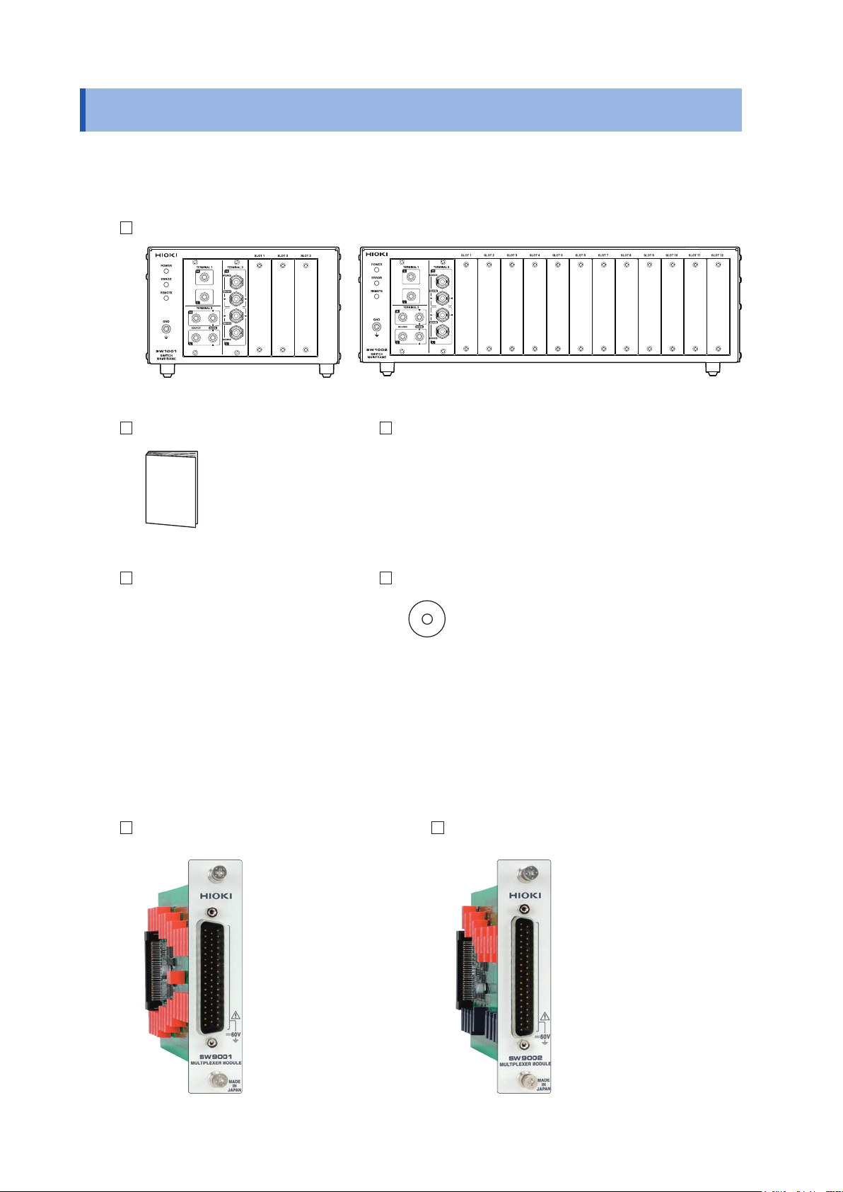
Options
The following options are available for the device. Contact your authorized Hioki distributor or
reseller when ordering.
Module
Model SW9001 Multiplexer Module
(2-wire/4-wire)
Model SW9002 Multiplexer Module
(4-terminal pair)
2
Conrming Package Contents
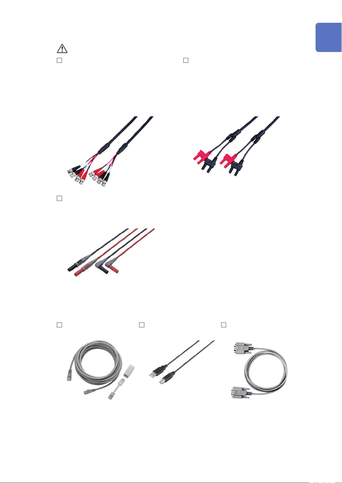
Connection cable
See: “Before measurement” (p. 5)
Model L2004 Connection Cable Model L2108 Connection Cable
Length: Approx. 910 mm Length: Approx. 840 mm
Maximum rated voltage: 30 V peak Maximum rated voltage: 60 V DC, 30 V AC rms,
42.4 V peak
Maximum rated voltage
to earth:
30 V DC or less, no
measurement category
Maximum rated voltage
to earth:
60 V DC or less, no
measurement category
1
Maximum rated current: 2.5 A peak Maximum rated current: 2 A peak
Model L4930 Connection Cable Set
Length: Approx. 1.2 m
Maximum rated voltage*: CAT III: 1000 V
CAT IV: 600 V
2
3
4
5
6
* Do not input voltage exceeding the rating of this device and the instrument.
Communications cable
Model 9642
LAN Cable
Model L1002
USB Cable (A-B)
7
8
Model 9637
RS-232C Cable (9pin-9pin/1.8 m)
9
10
Appx. Ind.
3
Safety Information
Safety Information
Be sure to also read the separate document “Operating Precautions” before use.
Usage Notes
Check before use
Follow these precautions to ensure safe operation and to obtain the full benets of the various
functions.
WARNING
If a connection cable or the device is damaged, there is a risk of an electric shock.
Perform the following inspection before using the device.
• Before using the device, check that the coating of the connection cables are
neither ripped nor torn and that no metal parts are exposed. Using the device
under such conditions could result in an electric shock. Replace any damaged
cable with a new one.
• Before using the device the rst time, verify that it operates normally to ensure
that no damage occurred during storage or shipping. If you nd any damage,
contact your authorized Hioki distributor or reseller.
This device is designed to measure voltages of 60 V or lower. Do not input
voltages over 60 V or measure locations exceeding 60 V from the ground potential.
If the relay of the device fails, the battery of the measuring object may be shorted
(p. 145).
Installing the device and module
CAUTION
Do not position the device on an unstable table or inclined surface. Dropping or
knocking down the device can cause injury or damage to the device.
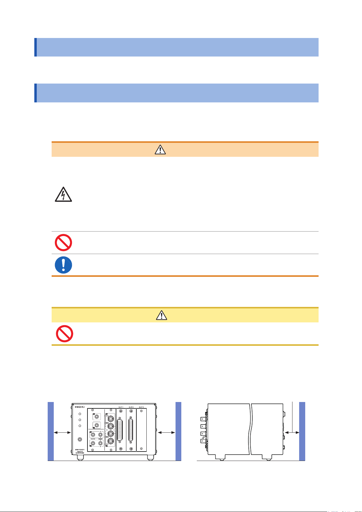
Installing
To prevent overheating, be sure to leave the specied clearances around the device.
• The device should be operated only with the bottom side downwards.
Rear: 10 mm or moreSide: 50 mm or more
4
Handling the device
This device may cause interference if used in residential areas. Such use must be avoided unless
the user takes special measures to reduce electromagnetic emissions to prevent interference to the
reception of radio and television broadcasts.
Before installing the module
WARNING
• To prevent an electric shock, before removing or replacing a module, conrm
that the device is turned off and that all the measurement cables, connection
cables, and the power cord are disconnected.
• Installing a module while the device is turned on may prevent detection of
the contact state of relays on the module or result in short-circuiting of the
measuring object. Damage of the device or module may cause the measuring
object to be shorted or the instrument to fail.
• Be careful about short circuits when connecting a measuring object with
electromotive force (battery, power supply, etc.).
• The maximum voltage of the device contact is 30 V (rms value) and 42.4 V (peak
value) or 60 V (direct current). Do not directly connect a withstand voltage tester
or an insulation resistance tester.
Usage Notes
1
2
3
4
When installing or removing the module, be sure to observe the following precautions:
• Touch the GND terminal of the device with your hand to release static and then use
antistatic gloves to perform procedures.
• Hold the sheet metal area of the module. Directly touching the board with your hand may
damage the circuit board due to static. If the measurement target has high resistance, the
error component due to factors such as oil from your ngers may increase in magnitude.
Before measurement
•
Do not short-circuit between electrodes or terminals using a probe when
measuring the battery or capacitor. Doing so may cause an electric arc, resulting
in serious injury.
• Do not use the device or the connection cables that exceed its ratings or
specications. Doing so may damage the device or cause it to become hot,
resulting in a bodily injury.
• Do not use the instrument to be used in conjunction with the device outside of
its ratings or specications. Doing so may damage the instrument or cause it to
become hot, resulting in a physical injury.
CAUTION
5
6
7
DANGER
8
9
10
WARNING
The maximum rated voltage between the module and ground is 60 V DC. To avoid
an injury and damage to the device, ensure that voltage between channels never
exceeds this limit. Prevent the voltage potential difference of the entire system
from exceeding 60 V DC.
The measurement connector frame of the module is connected to the casing (metal) of the device
as well as the protective ground terminal of the power inlet (conductive).
Appx. Ind.
5
Usage Notes
Before starting the external control
WARNING
To prevent an electric shock or damage to the device, always observe the
following precautions when connecting the cables to the EXT. I/O terminals.
• Always turn off the device and any devices to be connected before making
connections.
• Be careful to avoid exceeding the signal ratings of the EXT. I/O terminals.
• During operation, a wire becoming dislocated and contacting another
conductive object can be a serious hazard. Use screws to secure the external
connectors.
• Ensure that devices and systems to be connected to the EXT. I/O terminals are
properly isolated from one another.
Before connecting the communications cables
CAUTION
• Use a common ground for both the device and the PC. Using different ground circuits
will result in a potential difference between the device's ground and the computer's
ground. If the communications cable is connected while such a potential difference
exists, it may result in device malfunction or failure.
• Before connecting or disconnecting any communications cables, always turn off the
device and the PC. Failure to do so could result in equipment malfunction or damage.
• After connecting the communications cables, tighten the screws on the connector
securely. Failure to secure the connector could result in device malfunction or damage.
• To avoid device failure, do not disconnect the communications cables while
communications are in progress.
Precautions during shipment
Store the packaging in which the device was delivered, as you will need it when transporting the
device.
Disc precautions
• Exercise care to keep the recorded side of discs free of dirt and scratches. When writing text on
a disc’s label, use a pen or marker with a soft tip.
• Keep discs inside a protective case and do not expose to direct sunlight, high temperature, or
high humidity.
• Hioki is not liable for any issues your computer system experiences in the course of using this
disc.
6

1
Overview
1.1 Overview of Product
This device is a module type switching system that is ideal for multi-channel measurement of
batteries. You can choose a main frame from two choices according to the required number of
channels. You can also choose a module from two module types according to the instrument to be
used with the device (2-wire/4-wire module and 4-terminal pair module).
1.2 Features
Reduction of errors when measuring internal resistance
When AC low resistance measurement is performed using the BT4560 Battery Impedance Meter
or the BT3562 Battery HiTester, the inuence of electromagnetic induction (eddy current) on the
measured value can be minimized.
Ability to switch measurement between two instruments
For example, you can connect a BT3562 and DM7276 to the device and use it to switch between
internal resistance measurement and high-precision OCV measurement.
Protection against short circuit with fuses
To protect batteries to be measured if a short circuit occurs in a channel, a protective fuse is built
into each channel.
1
Overview
7
Parts Names and Functions
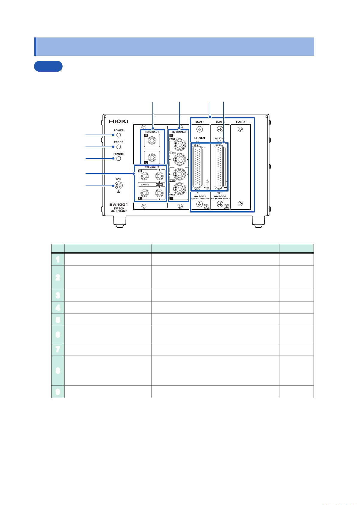
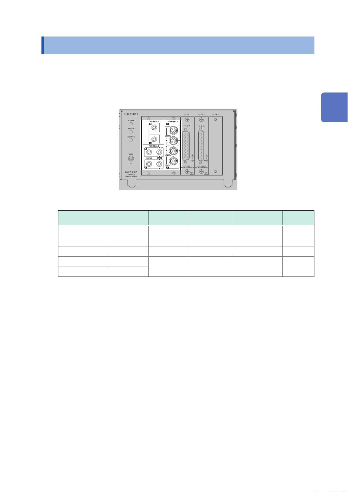
1.3 Parts Names and Functions
Front
The illustration shown here is for the SW1001.
4
6 7
8
1
2
3
5
9
No. Name Description Reference
POWER lamp Lights up when the main frame power is on. p. 23
1
Lights up for self-test at the time of startup and
ERROR lamp
2
REMOTE lamp Lights up when communications data is received. p. 86
3
TERMINAL 1 Used to connect a 2-wire instrument. p. 20
4
TERMINAL 2 Used to connect a 4-wire instrument. p. 20
5
TERMINAL 3
6
SLOT 1 to SLOT 3 Used to attach the module. p. 15
7
Measurement cable connector
8
GND terminal Ground for the device. Connected to the ground. p. 36
9
when an error, such as a communications error,
occurs.
Used to connect a 4-terminal pair (BNC terminal)
instrument.
Used to connect the measurement cable to each
module. For more details, see the chapter for the
multiplexer module.
p. 23
p. 126
p. 21
p. 5
p. 18
p. 133
p. 139
8
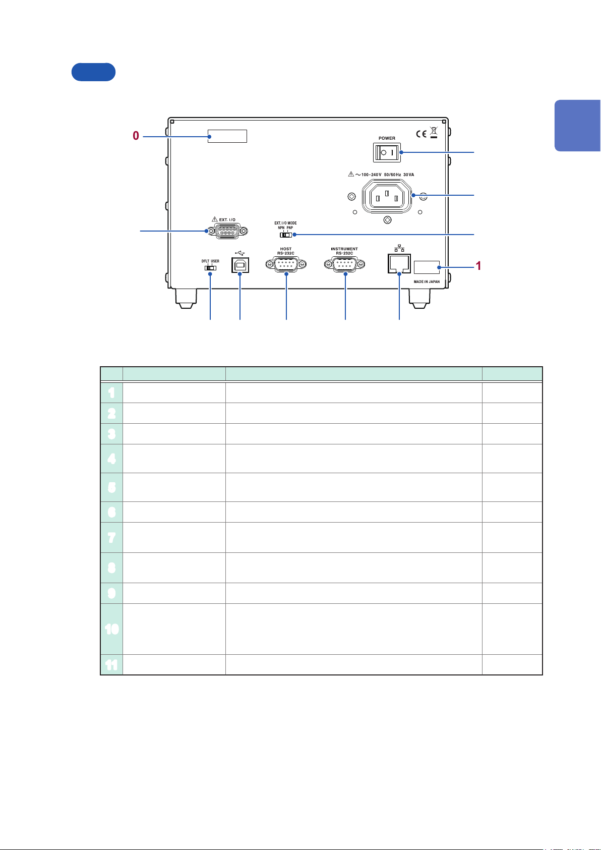
Rear
The illustration shown here is for the SW1001.
Parts Names and Functions
10
1
2
3
4
11
6 7 8 9
5
No. Name Description Reference
Power switch Turns on/off the power. p. 23
1
Power inlet Used to connect the provided power cord. p. 23
2
1
Overview
EXT. I/O terminal Used to connect the device to be externally controlled. p. 51
3
EXT. I/O MODE
4
change-over switch
Communication
5
setting mode switch
USB connector Used to connect the PC. p. 64
6
HOST
7
RS-232C connector
INSTRUMENT
8
RS-232C connector
LAN connector Used to connect the PC. p. 60
9
Serial number
10
MAC address MAC address of the LAN. p. 105
11
Left: Sinking current (NPN), Right: Sourcing current (PNP) p. 50
Perform communication using xed settings when the
communication settings are unknown.
Used to connect the PC. p. 66
Used to connect the RS-232C connector of the instrument for
scan measurement.
The serial number consists of 9 digits. The rst two (from
the left) indicate the year of manufacture, and the next two
indicate the month of manufacture.
Required for production control. Do not peel off the label.
p. 22
p. 70
–
9
Block Diagram
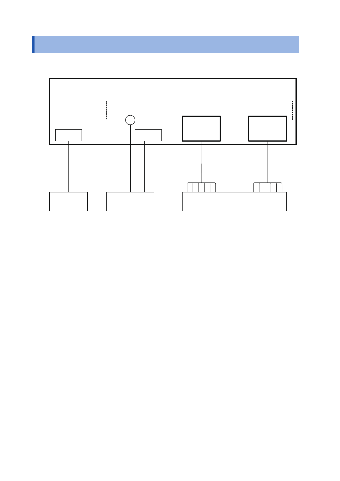
1.4 Block Diagram
The conguration of this device is shown in the following block diagram.
Switch Mainframe
Internal analog bus
Terminal Module
I/F EXT. I/O
Connection cable Measurement cable
PC/PLC
Instrument Measuring object
...
Module
10

1.5 Glossary
Terms Description Reference
Measurement cable Connects the measuring object and the module.
It is prepared by the customer.
Connection cable Connects the switch mainframe and instrument.
Prepare the optional cable.
Glossary
p. 143
p. 19
1
Overview
Terminal Connects the instrument.
The terminal to be used varies depending on the connection method
(2-wire/4-wire/4-terminal pair)
Module For the switching circuit.
The connection method varies depending on the module type.
Slot Used to attach the module.
The number of slots varies depending on the switch mainframe type.
Channel Channel inside the module.
Specify the slot and channel and select the measuring object.
Analog bus Common analog signal inside the switch mainframe.
The analog buses for 4 systems are built in.
The analog bus to be used is determined based on the connection
method.
Channel relay Switches the channel inside the module. p. 27
Bus relay Connects the measurement signal selected for the channel relay to
the analog bus.
It is built into the module.
Switching the bus relay allows you to select the connection method.
Connection method You can select the measurement connection from 2-wire, 4-wire, or
4-terminal pair.
Selecting a connection method determines the connection terminal for
the instrument.
p. 28
p. 129
p. 30
p. 30
p. 27
p. 27
p. 28
Shield For the measurement cable (cable for the measuring object).
The destination to which the shield is connected inside the module
can be switched.
Switching the connection destination can reduce the inuence of
noise depending on the instrument to be used or the measurement
environment.
Scan Switches the pre-registered channel (scan list) in sequence.
Connecting the instrument and this device using EXT. I/O enables
the channel to be switched and trigger measurement to be performed
automatically.
p. 29
p. 39
11
Measurement Flowchart
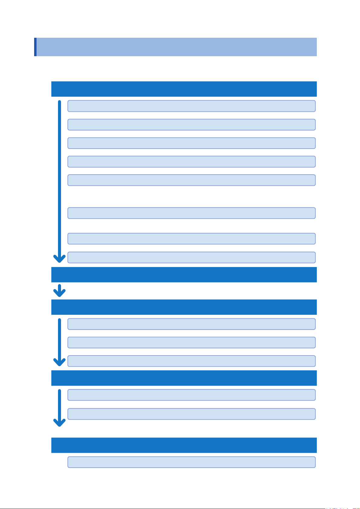
1.6 Measurement Flowchart
Thoroughly read “Usage Notes” (p. 4) beforehand.
Installation, connection, and turning on of power
Installing the device. (p. 4)
Attaching the module to the device. (p. 15)
Connecting the measurement cable to the module. (p. 18)
Connecting the device and the instrument using the connection cable. (p. 19)
Connecting the communications cable and making settings.
• Set the communication setting mode (p. 22).
• Connect the LAN, USB, or RS-232C cable to the PC (p. 59).
Connecting the device and the external control device. (for scan measurement)
• Connect the device to an external device such as a PLC using EXT. I/O (p. 49).
Connecting the power cord. (p. 23)
Turning on the power. (p. 23)
Inspection before measurement (p. 25)
Setting before measurement
Selecting the module connection method. (p. 28)
Switching the shield. (p. 29)
Selecting the channel to be measured. (p. 30)
Starting the measurement
12
Sending a measurement command to the instrument.
Receiving measurement results.
• For information on the measurement processing and receiving measurement results, see the
instruction manual of the instruments to be used.
Ending the measurement
Turning off the power. (p. 23)
2
Preparation for Measurements
2.1 Connecting Instruments and Controlling the Device
This section describes how to connect one or more measuring instruments and control the device.
A PC or PLC must be connected in order to control the device. A PC or PLC connection is also
required in order to control instruments and acquire measured values.
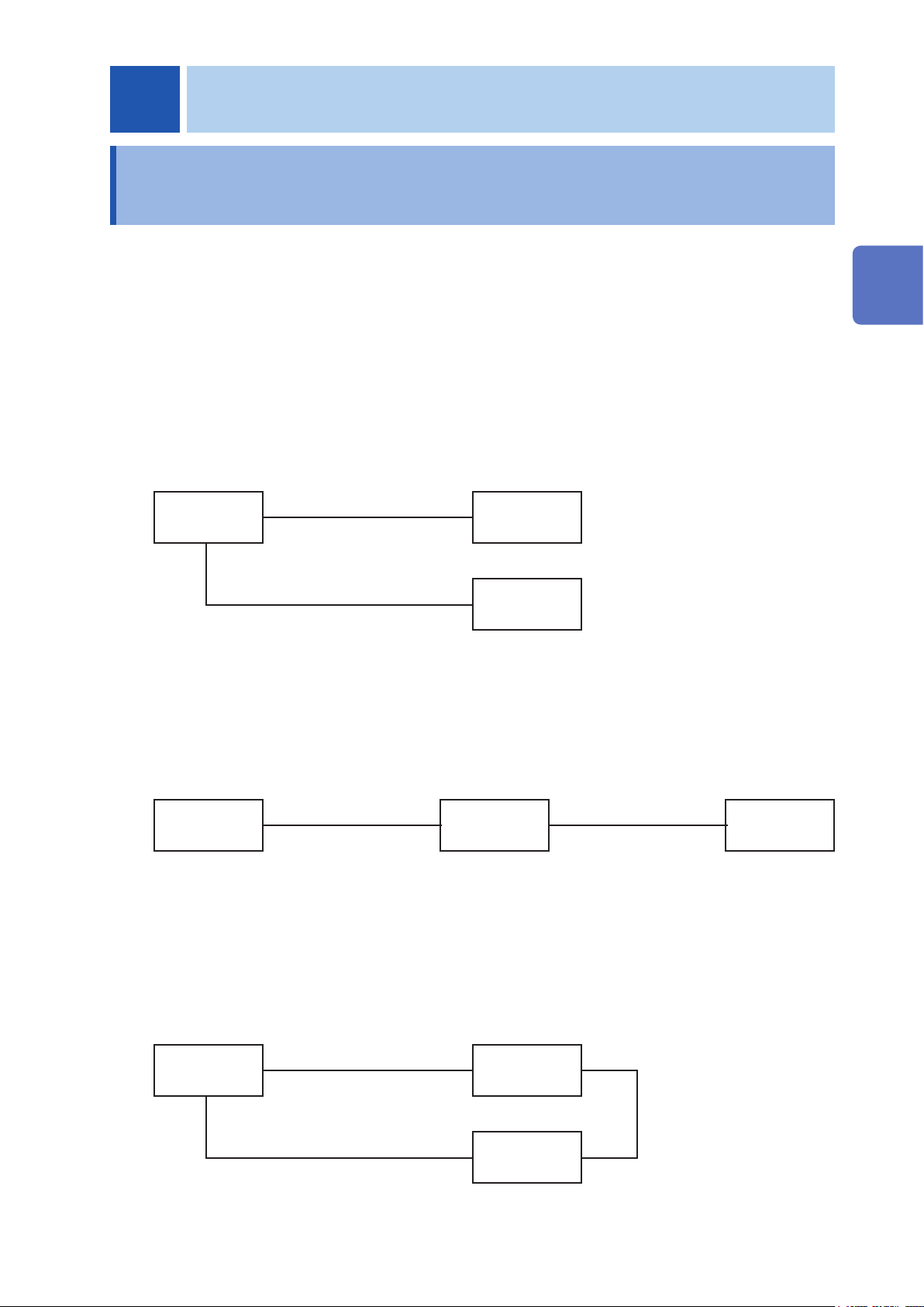
The device utilizes the connection and control methods described below.
Basic control
Connect the PC to the device and instrument via separate communications interfaces.
Control the device to switch channels and control the instrument to congure settings, perform
measurement, and acquire measured values.
See: “3.2 Overview of Channel Switching” (p. 27)
2
Preparation for Measurements
PC
LAN/USB/RS-232C
LAN/USB/RS-232C
SW1001
Instrument
Controlling an instrument via the device
You can also use the device’s functionality for forwarding communication commands to control
instruments simply by sending commands to the device.
See: “8.6 Communication Command Forwarding Function” (p. 69)
INSTRUMENT
PC
LAN/USB/RS-232C
SW1001
connector
RS-232C only
Performing automatic scan measurement using EXT. I/O
You can switch channels and perform a series of measurements in accordance with a previously
created scan list by connecting the device and an instrument via the EXT. I/O interface. You can
also acquire measured values by using the instrument’s data output function (to automatically send
measured values) or memory function.
See: “4 Scan Function” (p. 39)
Instrument
PC
LAN/USB/RS-232C
SW1001
EXT. I/O
Instrument
LAN/USB/RS-232C
13
Connecting Instruments and Controlling the Device
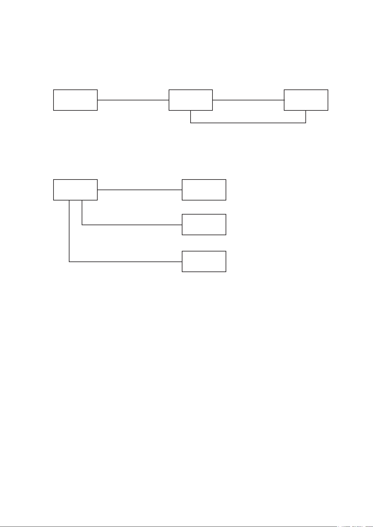
Performing automatic scan measurement using EXT. I/O
(using the communication command forwarding function)
Furthermore, you can perform automatic scan measurement over a single communications
interface by using the device’s communication command forwarding function.
INSTRUMENT
PC
LAN/USB/RS-232C
SW1001
connector
RS-232C only
EXT. I/O
Connecting two instruments
You can perform measurement by connecting two instruments to the device.
See: “3.5 Measurement between Two Instruments” (p. 32)
Instrument
PC
LAN/USB/RS-232C
SW1001
Instrument 1
LAN/USB/RS-232C
Instrument 2
LAN/USB/RS-232C
14
Installing the Module
2.2 Installing the Module
Thoroughly read “Before installing the module” (p. 5) beforehand.
The following settings are initialized when you install a new module into a slot or change the type of
module installed in a given slot.
• Connection method
• Shield switching
• Channel delay
• Scan list
Required items: Phillips screwdriver (No. 2), antistatic gloves
2
Preparation for Measurements
1
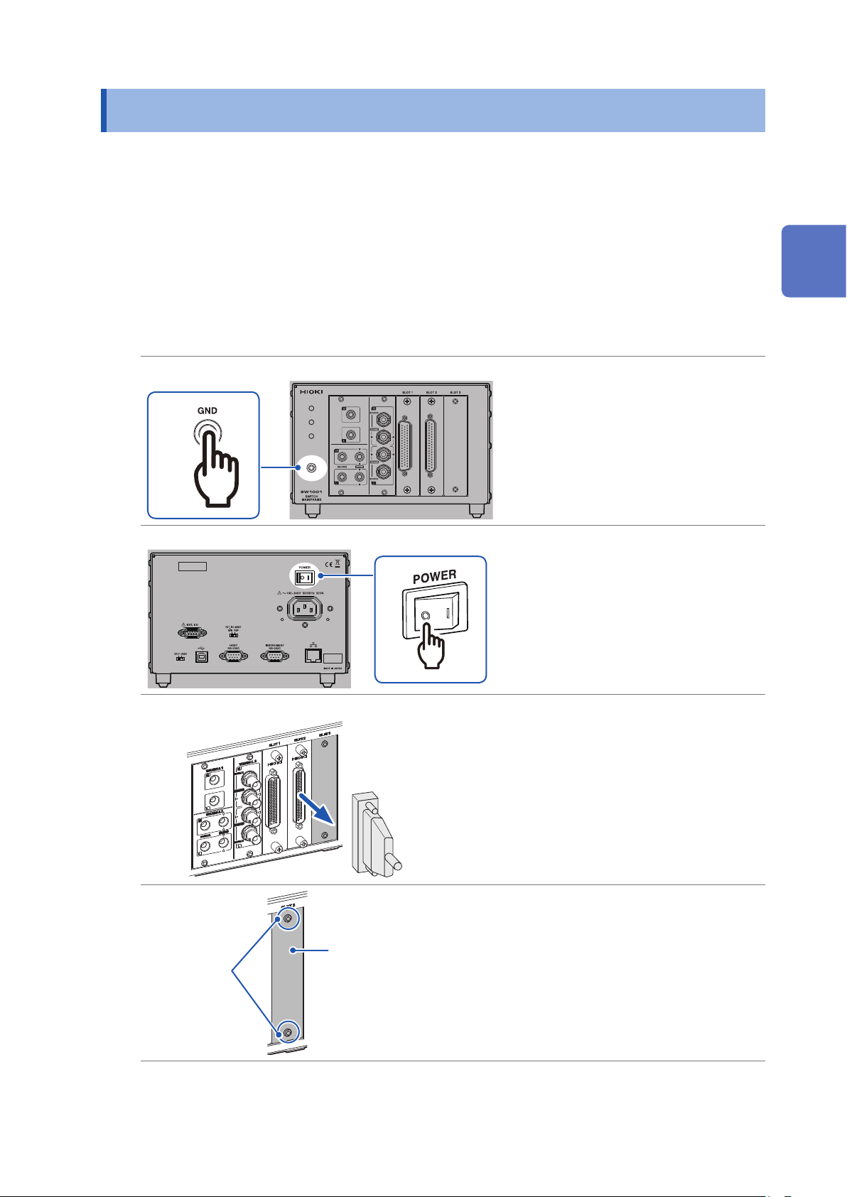
Rear
Front
Front
3
Touch the GND terminal with
1
bare hands.
Wear antistatic gloves.
2
Turn off the device.
3
Remove all the measurement
4
cables connected to the device
and module.
(To prevent electric shock and short
circuit of the measuring object.)
Screw
(M3 × 6 mm)
Blank panel
Loosen the two screws
5
(M3 × 6 mm) and then remove
the blank panel.
Store the blank panel and screws.
You need the screws when using the
device after removing the module.
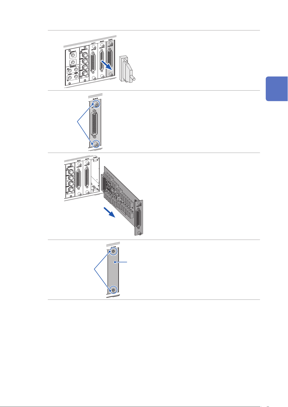
15
Removing the Module
Align with the guide rail
Insert the module to the back.
6
Tighten the two screws to
7
secure the module in place.
Screw
2.3 Removing the Module
Required items: Phillips screwdriver (No. 2), antistatic gloves
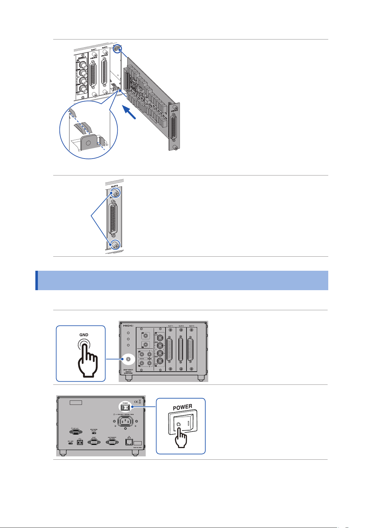
Front
1
Rear
Touch the GND terminal with
1
bare hands.
Wear antistatic gloves.
2
Turn off the device.
3
16
3
Removing the Module
Front
Screw
Remove all the measurement
4
cables connected to the
device and module.
(To prevent electric shock and short
circuit of the measuring object.)
Loosen the two screws.
5
Pull out the module.
6
2
Preparation for Measurements
Screw
(M3 × 6 mm)
Blank panel
Attach the blank panel and
7
tighten the two screws
(M3 × 6 mm) to secure the
panel.
17
Connecting the Measurement Cable
2.4 Connecting the Measurement Cable
WARNING
Connect the measurement cable with the measuring object disconnected from
the measurement cable. The measuring object may be shorted depending on the
condition of the module switching circuit.
Please provide a suitable measurement cable.
See: “12.1 Measurement cable” (p. 143)
Turn off the device.
1
Disconnect the probe from the
Disconnect
Measuring object
2
measuring object.
Disconnect
Tip of the probe
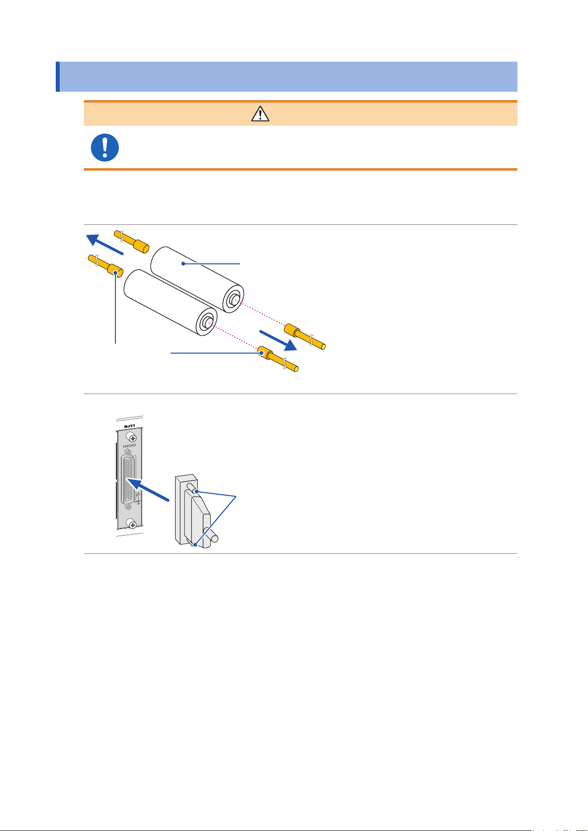
Front
Connect the measurement
3
cable connector to the module’s
connector.
Secure the measurement cable
4
connector using the screws.
3
4
For information on connecting the measuring object, see the instruction manual of each instrument.
18
Connecting the Connection Cable
2.5 Connecting the Connection Cable
The connection cable is optional (p. 2).
Connect the device to the instrument.
For information on connecting the instrument, see the instruction manual of each instrument.
Front
2
Preparation for Measurements
Select the terminal and connection cable to be connected based on the instrument to be connected.
Instrument
example
Voltmeter DM7276 TERMINAL 1 L4930 2-wire
Battery tester BT3562 TERMINAL 2 L2108 4-wire SW9001
Battery tester BT4560
LCR meter IM3590
Model Terminal
TERMINAL 3 L2004 4-terminal pair SW9002
Connection
cable
Connection
method
Module
SW9001
SW9002
19

Connecting the Connection Cable
TERMINAL 2 and TERMINAL 3 are internally conducted. Do not connect the instrument
to TERMINAL 2 and TERMINAL 3 at the same time. Doing so may damage the
instrument.
TERMINAL 1
Turn off the device.
1
Connect the connection cable to TERMINAL 1.
2
CAUTION
Front
Connect the other end of the connection cable to the instrument.
3
TERMINAL 2
Turn off the device.
1
Connect the connection cable to TERMINAL 2.
2
Connect the connection cable so that the red
lead wire match and the black
match.
Red
Black
H
L
mark of the device and the
mark of the device and the
Front
mark of the black lead wire
mark of the red
20
H
Red
L
Black
Connect the other end of the connection cable to the instrument.
3

TERMINAL 3
Turn off the device.
1
Connect the connection cable to TERMINAL 3.
2
Connecting the Connection Cable
Match the cable and the connection
terminal signal.
SOURCE-H (red)
SENSE-H (red)
SENSE-L (black)
SOURCE-L (black)
1. Check the direction of
the grooves of the BNC
connector. The grooves
should t into the connector
guide of the device.
Device side
Connector guide
Front
2. Align the grooves of the
BNC connector with the
connector guide of the
device and insert the BNC
connector.
2
Preparation for Measurements
3. Turn the BNC connector to
the right to lock it.
BNC connector grooves of
the connection cord
Connect the other end of the connection cable to the instrument.
3
Connection cable terminal
SOURCE-H (red) SOURCE-H (red) Hcur
SENSE-H (red) SENSE-H (red) Hpot
SENSE-L (black) SENSE-L (black) Lpot
SOURCE-L (black) SOURCE-L (black) Lcur
BT4560 IM3590
Instrument terminal
21
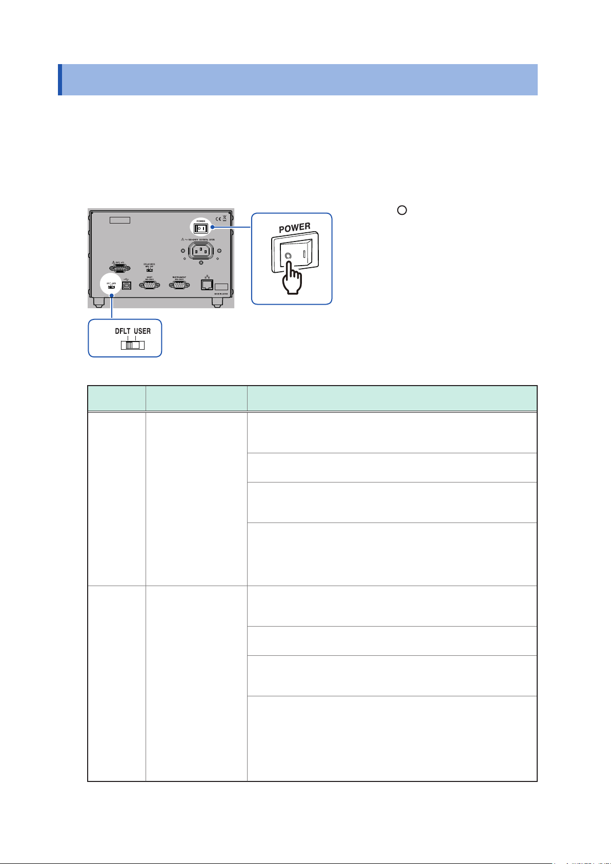
Setting the Communication Setting Mode
2.6 Setting the Communication Setting Mode
The device uses the communications interface for control.
You can select the xed setting mode for initial communication settings or the user setting mode for
user settings using the switch on the rear of the device.
Specify the communication settings according to the interface to be used in the user setting mode.
Reference: “8.1 Interface Overview and Features” (p. 59)
Rear
Check that the power switch is
1
off ( ).
Change the communication
1
2
setting mode using the
communication setting mode
switch.
2
Switch
DFLT Fixed setting mode All of USB, RS-232C, and LAN can be used.
Communication
setting mode
Device setting description
Communications are performed using the specied communication
settings.
• USB
No setting item
• RS-232C
Transmission speed: 9600 bps, data bits: 8; stop bit: 1; parity
check: none; ow control: none
• LAN
IP address: 192.168.0.254
Subnet mask: 255.255.255.0
Default gateway: 0.0.0.0 (None)
Communication command port number: 23
USER User setting mode All of USB, RS-232C, and LAN can be used.
Use the communication settings that are specied using the following
communication commands.
• USB
No setting item
• RS-232C
:SYSTem:COMMunicate:RS232C:SPEED <
Reference: “(8) RS-232C settings” (p. 103)
• LAN
:SYSTem:COMMunicate:LAN:IPADdress <
:SYSTem:COMMunicate:LAN:SMASk <
:SYSTem:COMMunicate:LAN:GATeway <
:SYSTem:COMMunicate:LAN:CONTrol <
:SYSTem:COMMunicate:LAN:UPDate
Reference: “(9) LAN settings” (p. 103)
Subnet mask
Transmission speed
IP address
Gateway address
Port No.
>
>
>
>
>
22
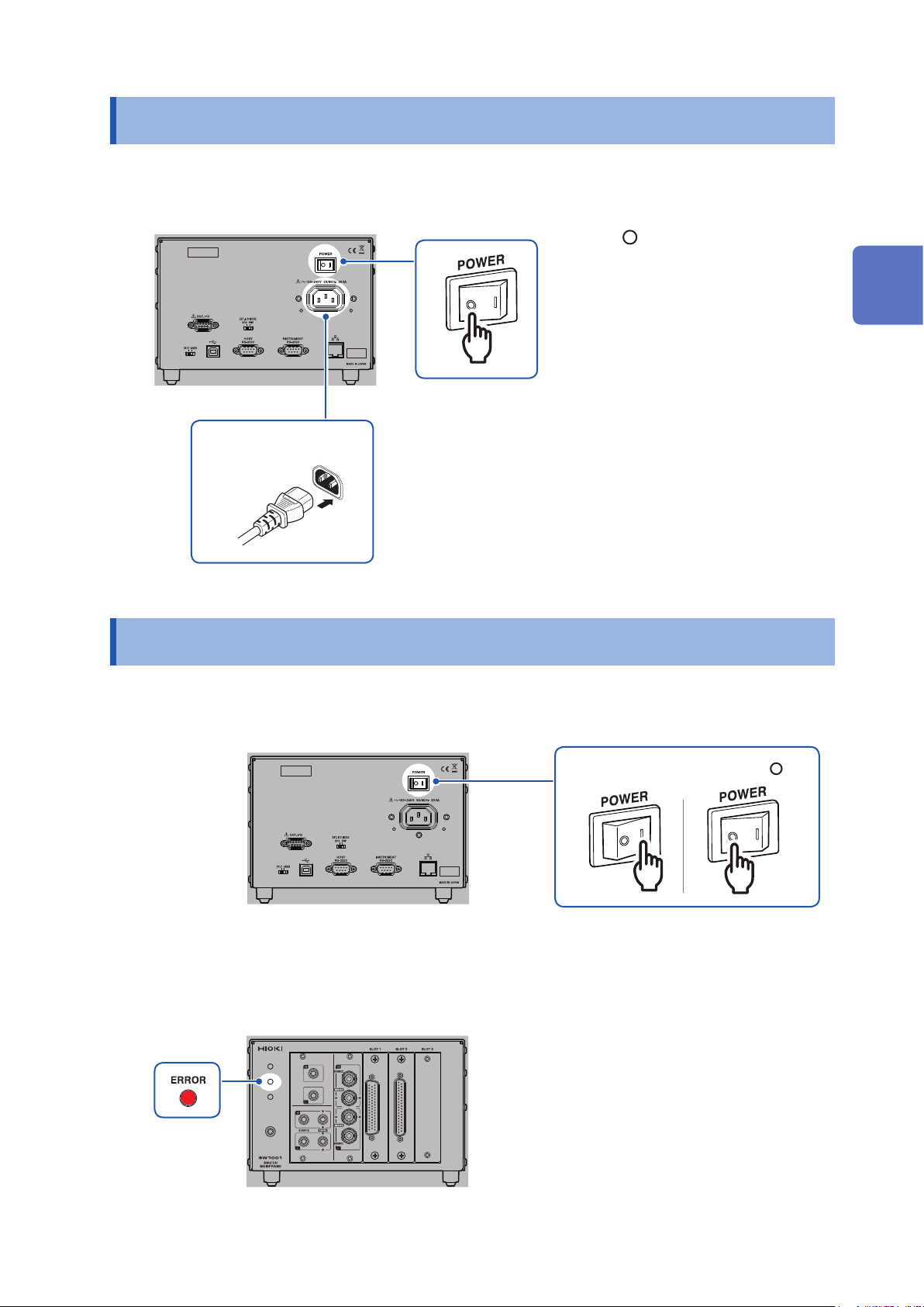
Connecting the Power Cord
2.7 Connecting the Power Cord
Be sure to thoroughly read the separate document “Operating Precautions” before use.
Rear
1
Power inlet
2
2.8 Turning on/off the Power
Check that the power switch is
1
off ( ).
Check that the power voltage is
2
within the range indicated on the
rear of the device and connect
the power cord to the power
inlet.
Connect the plug of the power
3
cord to the outlet.
2
Preparation for Measurements
Use the power switch on the rear of the device to turn on/off the power.
Rear
Power off ( )Power on (I)
The front POWER lamp lights up when the device is turned on, and a self-test is executed.
When an error occurs, the ERROR lamp on the front lights up. If an error occurs during self-test,
communications and control using EXT. I/O become disabled.
Front
23
When the Power is Turned on
2.9 When the Power is Turned on
Item Initialization description
Channel relay All relays open
Bus relay All relays open
EXT. I/O CLOSE output signal Off
Connection method Settings (for each slot) are saved with the settings backup command.
Shield switching Settings (for each slot) are saved with the settings backup command.
Scan settings Settings are saved with the settings backup command.
Channel delay settings Settings are saved with the settings backup command.
Communication settings Settings are saved with the settings backup command.
See: “Backing up settings” (p. 105)
24
3
Channel Switching
Thoroughly read "Usage Notes" (p. 4) beforehand.
3.1 Inspection before Measurement
Verify that it operates normally to ensure that no damage occurred during storage or shipping.
If you nd any damage, contact your authorized Hioki distributor or reseller.
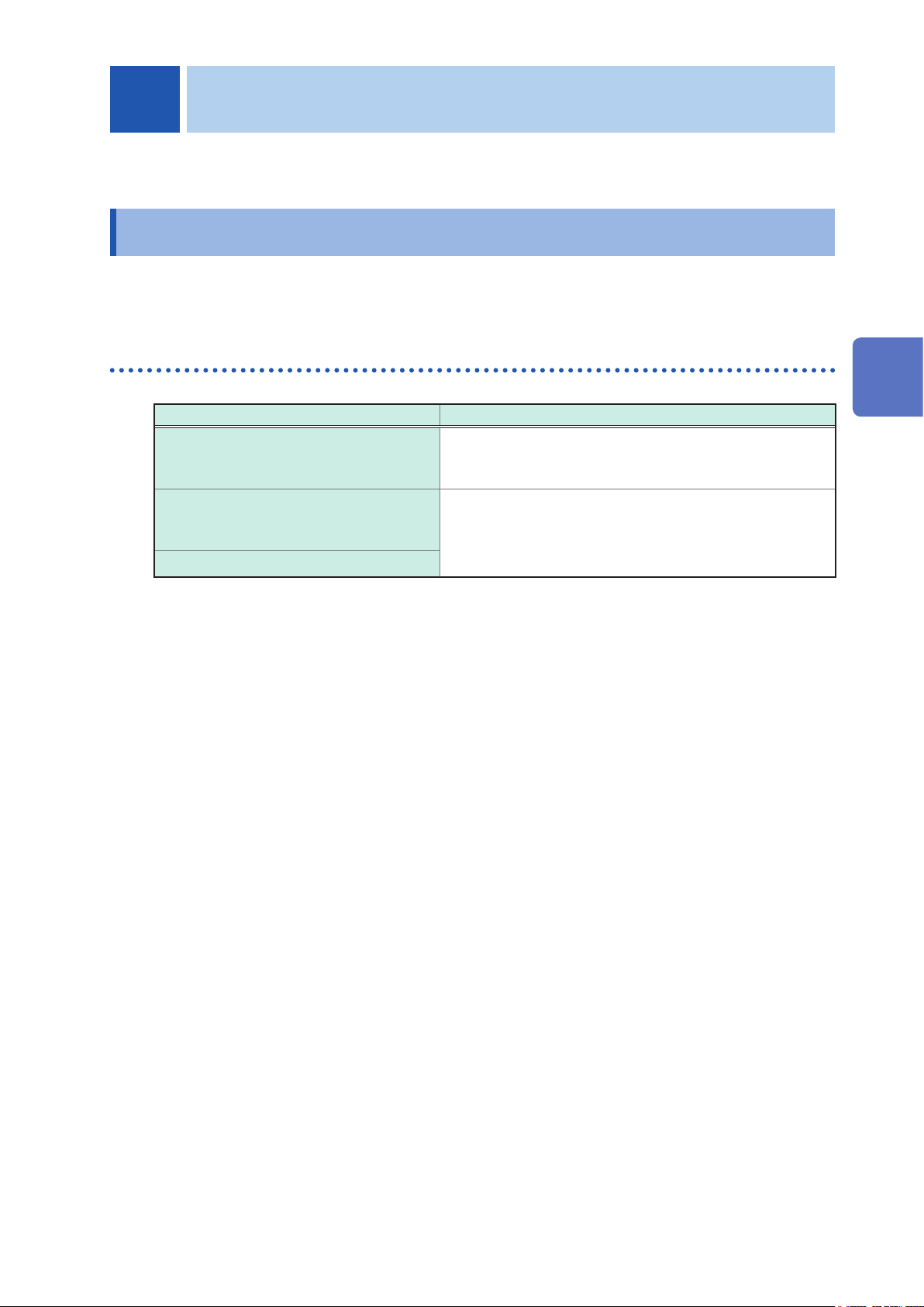
Inspecting the device and peripheral devices
3
Check item Action
Is the sheath of the power cord normal
without any damage or exposed metal part?
Are the sheaths of the measurement cables
or connection cables to be used normal
without any damage or exposed metal part?
Is the device normal without any damage?
Channel Switching
Damage may cause an electric shock or a short circuit
accident. Do not use it.
Contact your authorized Hioki distributor or reseller.
Damage may cause an electric shock. Stop using it and
replace it with a specied one.
25
Inspection before Measurement
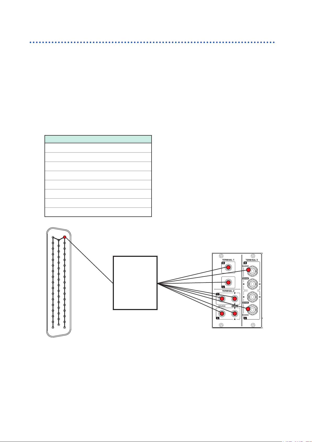
Checking for relay contact welding
If a relay contact welds, the battery of the measuring object may short or the channels may be
connected in parallel, resulting in improper measurement.
You can check that the relays are not welded according to the following procedure.
Short all the module terminals.
1
Send inspection command: TEST:RELAYSHORT <No. of slot to be inspected>,CH, and set the
2
test state of the channel relay.
Example: Inspect the channel relay of SLOT 1.
:TEST:RELAYSHORT 1,CH
Check that the terminals of the shorted modules and the following points of the terminals on
3
the main frame are not electrically connected.
Continuity inspection points
TERMINAL 1, H
TERMINAL 1, L
TERMINAL 2, SENSE H
TERMINAL 2, SENSE L
TERMINAL 2, SOURCE H
TERMINAL 2, SOURCE L
TERMINAL 3, SOURCE H shield
TERMINAL 3, SOURCE L shield
17
1
33
18
The connector is for the SW9001.
50
Check that the terminal of the shorted
module and the above points of the
34
terminal on the main frame are not
electrically connected.
Tester
Send inspection command: TEST:RELAYSHORT <No. of slot to be inspected>,BUS, and set the
4
test state of the bus relay, then conrm step 3.
Send inspection command: TEST:RELAYSHORT <No. of slot to be inspected>,OPEN, and end the
5
inspection for this slot.
Perform steps 1 to 5 for all the slots.
6
Module relay contact may be weld if it was conducted during inspection. Stop the use and contact
your authorized Hioki distributor or reseller.
26
 Loading...