

Hioki ST5520-01, ST5520 Instruction Manual
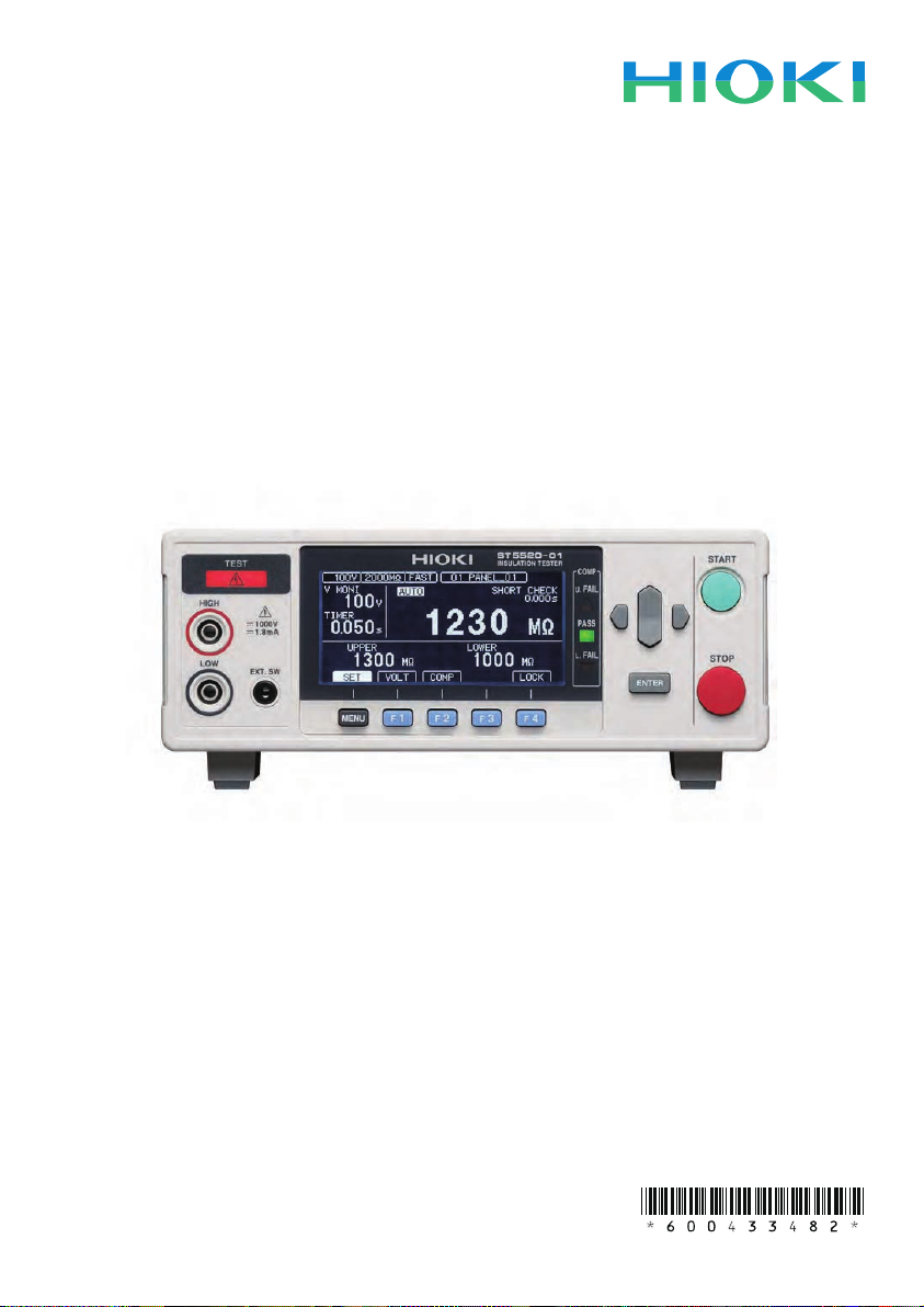
ST5520
ST5520-01
Instruction Manual
INSULATION TESTER
Aug.2015 Revised edition 2
ST5520A981-02 15-08H
EN


Contents
Introduction ........................................................................................1
Verifying Package Contents .............................................................1
Safety Notes .......................................................................................3
Usage Notes .......................................................................................7
1 Overview 15
1.1 Product Overview and Features ...........................................15
■Overview ............................................................................................15
■Features .............................................................................................16
1.2 Parts Names and Functions ..................................................17
1.3 MeasurementWorkow .........................................................19
1.4 ScreenCongurationandOperationOverview ..................20
■Measurement screen..........................................................................20
■Settings screen...................................................................................21
2 Preparations 23
2.1 Connecting the Power Cord ..................................................23
2.2 Connecting the Measurement Leads ...................................24
■Removing and attaching the sleeves .................................................25
2.3 ConnectingtotheEquipmenttobeMeasured ....................26
2.4 Turning the Power On and Off ..............................................26
■Turning on the power .........................................................................26
■Turning off the power..........................................................................26
2.5 Pre-OperationInspection ......................................................27
■Checking the insulation resistance test ..............................................28
■Checking the contact check function ..................................................29
1
2
3
4
5
6
7
8
9
10
Appx. Ind.
3 Basic Settings 33
3.1 Setting the Test Voltage .........................................................34
ST5520A981-02
i

Contents
3.2 Setting the Range ...................................................................36
3.3 SwitchingtheMeasurementSpeed(FAST/SLOW) .............38
3.4 SettingtheTestDurationandResponseTime ....................39
■Setting how long to apply the test voltage ..........................................39
■Setting the response time...................................................................41
3.5 JudgingMeasuredValues(Comparatorfunction) ..............44
3.6 Setting the Test Mode ............................................................46
3.7 AnnouncingtheJudgmentResultsUsingaBeepSound .47
4 Testing 49
4.1 Starting Measurements .........................................................49
4.2 During Measurement .............................................................51
4.3 MeasuredValueDisplay ........................................................52
4.4 CompletingMeasurement .....................................................53
4.5 AutomaticDischargeFunction .............................................54
5 Useful Functions 55
5.1 CheckingFaultyContactandContactStatus(Contact
checkfunction) .......................................................................56
■Connecting test leads .........................................................................58
■Example of connection to equipment to be measured .......................58
■2-terminal contact check function .......................................................59
5.2 CheckingShortCircuitbeforeApplyingtheSetVoltage
(Shortcircuitcheckfunction) ...............................................60
5.3 Enabling/DisablingtheKeyOperations ...............................65
5.4 SettingtheKeyOperationSound .........................................67
5.5 PreventingOperationErrorsattheStartofTesting
(Doubleactionfunction) ........................................................68
5.6 AdjustingtheScreenContrast .............................................69
5.7 AdjustingtheBacklight .........................................................70
5.8 SettingtheFrequencyofPowerSupplyManually ..............71
5.9 InitializingtheSystem(Reset) ..............................................72
ii

Contents
5.10 Default Setting List ................................................................73
6 Saving and Loading Measurement Conditions
(Memoryfunction) 75
6.1 Saving the Measurement Conditions
(Panelsavefunction) .............................................................76
6.2 Loading the Measurement Conditions
(Panelloadfunction) ..............................................................77
6.3 Changing the Panel Name .....................................................78
6.4 Deleting the Panel Data .........................................................79
7 ExternalControl(EXT.I/O) 81
7.1 ExternalInput/OutputTerminalandSignals........................82
■Switching between current sink (NPN) and current source (PNP) .....82
■Connector type and signal pinouts .....................................................83
■Signal descriptions .............................................................................86
7.2 Timing Chart ...........................................................................88
7.3 InternalCircuitConguration ...............................................96
■Electrical specications ......................................................................98
■Connection examples .........................................................................99
7.4 Setting the TEST Signal OFF Timing ..................................101
7.5 Checking External Control ..................................................103
■Performing an I/O test (EXT.I/O test function) ..................................103
7.6 UsingAnalogOutput ...........................................................104
■Connecting the output cord ..............................................................105
■Setting the analog output .................................................................105
7.7 Interlock Function ................................................................106
7.8 UsingtheSwitchedProbe ...................................................108
■Connecting the 9299 Switched Probe ..............................................109
7.9 AccessoryConnectorAssembly ........................................111
1
2
3
4
5
6
7
8
9
10
Appx. Ind.
iii

Contents
8 Communications(RS-232Cinterface) 113
8.1 Interface Overview and Features ........................................113
8.2 Using the RS-232C Interface ...............................................114
■Setting communications conditions ..................................................114
■Connecting the RS-232C cable ........................................................115
8.3 AutomaticallyExportingMeasuredValuesattheEnds
ofTests(Dataoutputfunction) ...........................................117
8.4 ControllingtheInstrumentandAcquiringDatawith
Commands ............................................................................119
■Remote and local states ...................................................................119
■Displaying communications commands (Communications monitor
function)............................................................................................120
8.5 DataFormatTable ................................................................125
8.6 Command Reference ...........................................................126
9 Specications 151
■Environment and safety....................................................................151
■Output (output accuracy) ..................................................................151
■Resistance measurement ................................................................153
■Input .................................................................................................154
■Guaranteed accuracy .......................................................................154
■Test duration ....................................................................................155
■Response time .................................................................................156
■Functions ..........................................................................................156
■External interface .............................................................................159
■Other specications ..........................................................................162
■Accessories ......................................................................................164
■Options .............................................................................................164
10 Maintenance and Service 165
10.1 Maintenance .........................................................................165
10.2 Troubleshooting ...................................................................167
iv

Contents
■Error display and solutions ...............................................................171
Appendix Appx.1
Appx.1 BlockDiagram .......................................................Appx.1
Appx.2 ContactCheckFunction .......................................Appx.2
Appx.3 OutputVoltageandMeasurementResistance ...Appx.3
Appx.4 InuenceofCapacitiveLoad ...............................Appx.4
Appx.5 InuenceofCableLength ....................................Appx.6
Appx.6 InuenceofNoise .................................................Appx.7
Appx.7 RackMounting ....................................................Appx.10
Appx.8 DimensionalDiagram .........................................Appx.14
Index Ind.1
1
2
3
4
5
6
7
8
9
10
Appx. Ind.
v

Contents
vi
Introduction
Introduction
Thank you for choosing the HIOKI ST5520/ST5520-01 Insulation Tester. To obtain
maximum performance from the product, please read this manual rst, and keep it
handy for future reference.
The ST5520-01 is equipped with the BCD output function of the ST5520. The artwork
of the ST5520 is used in this manual.
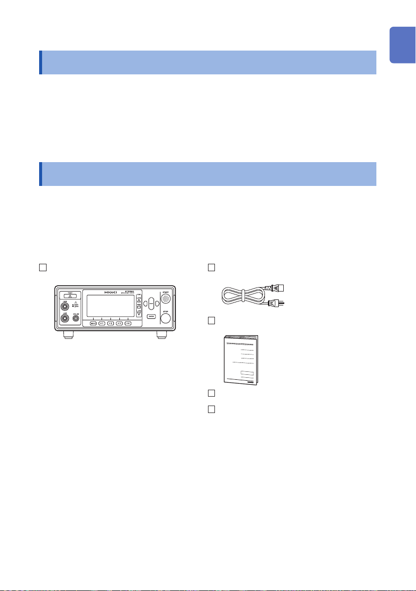
Verifying Package Contents
When you receive the instrument, inspect it carefully to ensure that no damage
occurred during shipping. In particular, check the accessories, panel switches,
and connectors. If damage is evident, or if it fails to operate according to the
specications, contact your authorized Hioki distributor or reseller.
Check the package contents as follows.
ST5520 or ST5520-01
Insulation Tester .........................................1
Power cord .................................................1
Instruction Manual ......................................1
1
2
3
4
5
6
7
EXT.I/O connector (pin contacts) ................1
EXT.I/O connector cover.......................1 set
8
9
10
Appx. Ind.
1
Verifying Package Contents
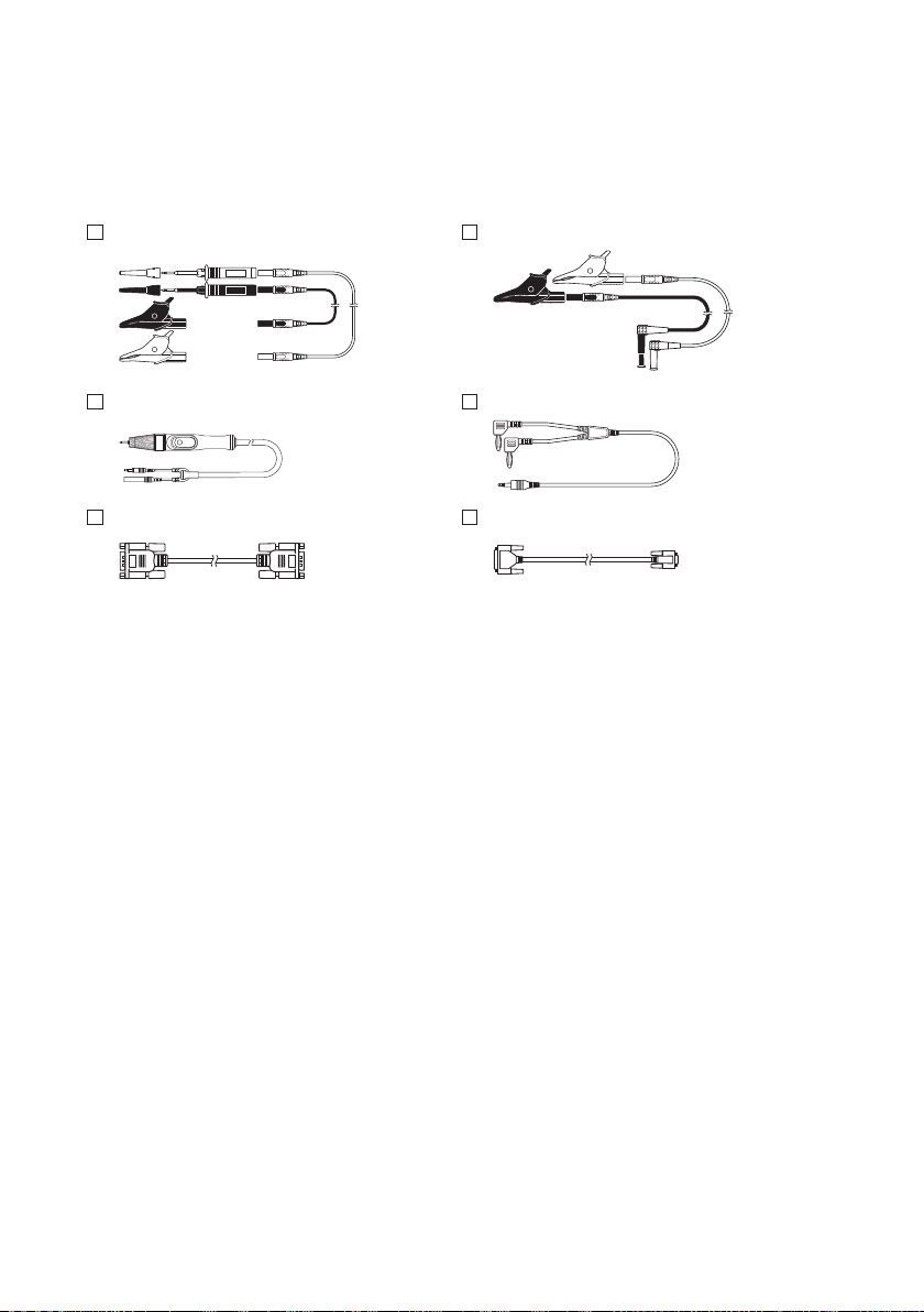
Options
The following options are available for ST5520/ST5520-01. Contact your authorized
Hioki distributor or reseller when ordering.
L2200 Test Lead L9257 Connection Cord
9299 Switched Probe 9094 Output Cord (analog output)
9637 RS-232C Cable (9pin-9pin/1.8 m) 9638 RS-232C Cable (9pin-25pin/1.8 m)
2

Safety Notes
Safety Notes
This instrument is designed to conform to IEC 61010 Safety Standards, and has been
thoroughly tested for safety prior to shipment. However, using the instrument in a way
not described in this manual may negate the provided safety features.
Before using the instrument, be certain to carefully read the following safety notes.
DANGER
Mishandling during use could result in injury or death, as well
as damage to the instrument. Be certain that you understand the
instructions and precautions in the manual before use.
WARNING
With regard to the electricity supply, there are risks of electric shock,
heat generation, re, and arc discharge due to short circuits. If
persons unfamiliar with electricity measuring instruments are to use
the instrument, another person familiar with such instruments must
supervise operations.
1
2
3
4
5
6
7
8
9
10
Appx. Ind.
3
Safety Notes
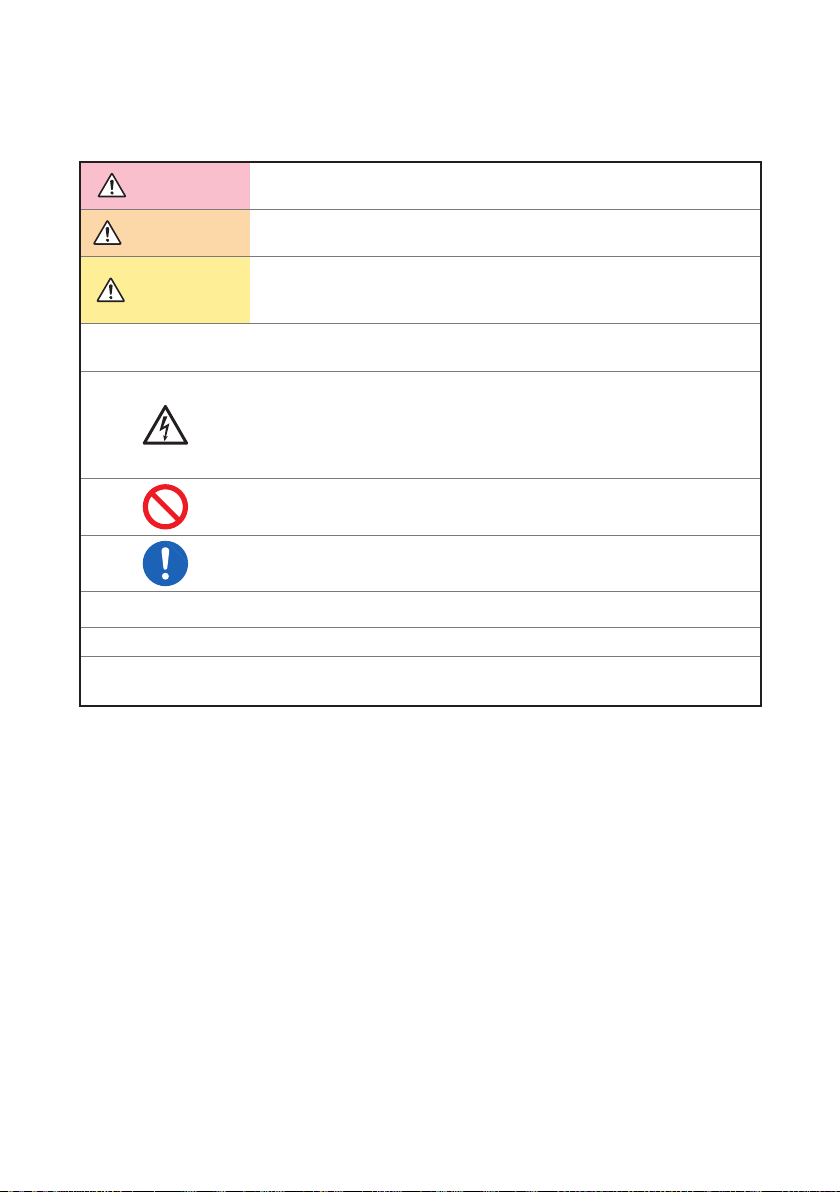
Notation
In this manual, the risk seriousness and the hazard levels are classied as follows.
DANGER
WARNING
CAUTION
IMPORTANT
*
[ ]
SET
(Boldface)
Indicates an imminently hazardous situation that will result in death or
serious injury to the operator.
Indicates a potentially hazardous situation that may result in death or
serious injury to the operator.
Indicates a potentially hazardous situation that may result in minor
or moderate injury to the operator or damage to the instrument or
malfunction.
Indicates information related to the operation of the instrument or
maintenance tasks with which the operators must be fully familiar.
Indicates a high voltage hazard.
If a particular safety check is not performed or the instrument is
mishandled, this may give rise to a hazardous situation; the operator
may receive an electric shock, may get burnt or may even be fatally
injured.
Indicates prohibited actions.
Indicates the action which must be performed.
Additional information is presented below.
Indicates set items and buttons on the display in [ ].
Bold-faced alphanumeric characters in the text indicate characters
shown on the operation keys.
4
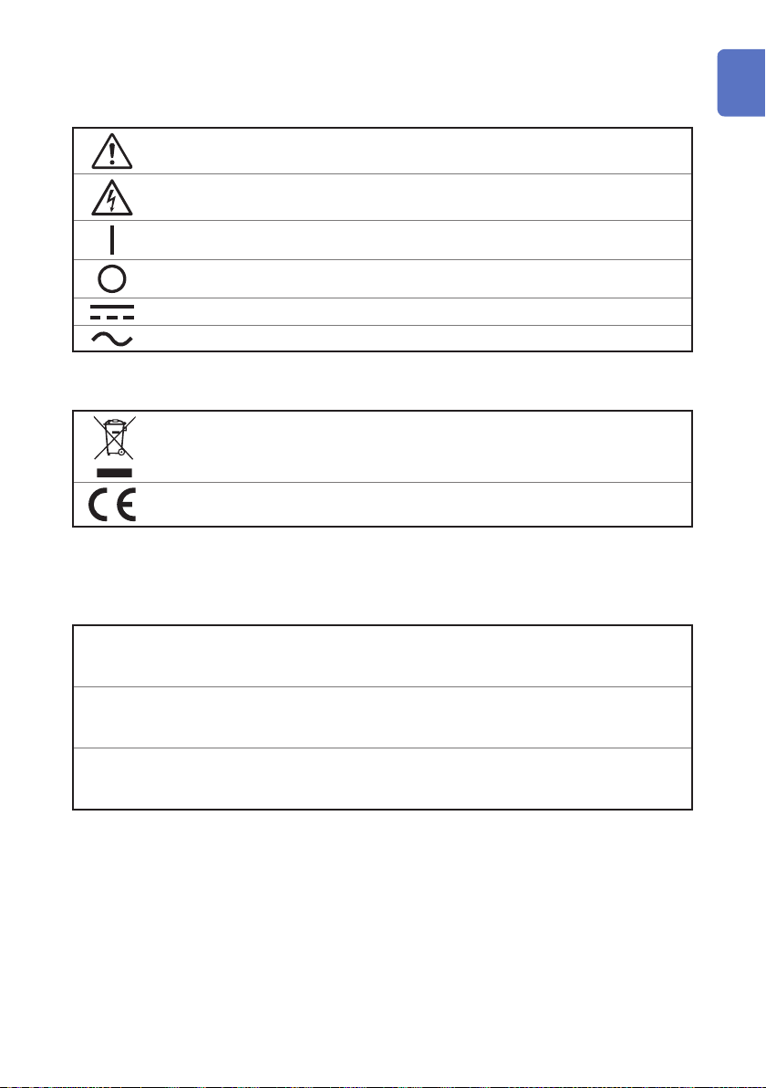
Symbols afxed to the instrument
Indicates cautions and hazards. When the symbol is printed on the instrument,
refer to a corresponding topic in the Instruction Manual.
Indicates that dangerous voltage may be present at this terminal.
Safety Notes
1
Indicates the power “ON”.
Indicates the power “OFF”.
Indicates DC (Direct Current).
Indicates AC (Alternating Current).
Symbols for various standards
Indicates the Waste Electrical and Electronic Equipment Directive (WEEE
Directive) in EU member states.
Indicates that the instrument conforms to regulations set out by the EC Directive.
Accuracy
We dene measurement tolerances in terms of f.s. (full scale), rdg. (reading), and
dgt. (digit) values, with the following meanings:
(Maximum display value, scale length)
f.s.
rdg.
dgt.
The maximum display value or the full length of the scale. This is usually the
maximum value of the currently selected range.
(Reading or displayed value)
The value currently being measured and indicated on the measuring
instrument.
(Resolution)
The smallest displayable unit on a digital measuring instrument, i.e., the input
value that causes the digital display to show a “1” as the least-signicant digit.
2
3
4
5
6
7
8
9
10
Appx. Ind.
5
Safety Notes
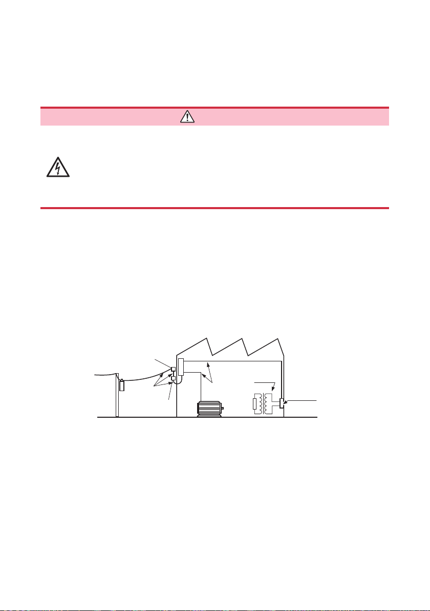
Measurement categories
To ensure safe operation of measuring instruments, IEC 61010 establishes safety
standards for various electrical environments, categorized as CAT II to CAT IV, and
called measurement categories.
DANGER
• Using a measuring instrument in an environment designated with
a higher-numbered category than that for which the instrument
is rated could result in a severe accident, and must be carefully
avoided.
• Using a measuring instrument without categories in an environment
designated with the CAT II to CAT IV category could result in a
severe accident, and must be carefully avoided.
CAT II: When directly measuring the electrical outlet receptacles of the primary
electrical circuits in equipment connected to an AC electrical outlet by a
power cord (portable tools, household appliances, etc.)
CAT III: When measuring the primary electrical circuits of heavy equipment (xed
installations) connected directly to the distribution panel, and feeders from
the distribution panel to outlets
CAT IV: When measuring the circuit from the service drop to the service entrance,
and to the power meter and primary overcurrent protection device
(distribution panel)
Service entrance
Service drop
CAT IV
Power meter
Distribution panel
Internal
wiring
CAT III
Fixed installation
CAT II
T
Outlet
6
Usage Notes
Usage Notes
Follow these precautions to ensure safe operation and to obtain the full benets of
the various functions.
Preliminary checks
DANGER
If the probe or the instrument is damaged, there is a risk of electric
shock. Before using the instrument, perform the following inspection.
• Before using the instrument, check that the coating of the probes
are neither ripped nor torn and that no metal parts are exposed.
Using the instrument under such conditions could result in electric
shock. Replace the probes with those specied by our company.
• Before using the instrument the rst time, verify that it operates
normally to ensure that no damage occurred during storage or
shipping. If you nd any damage, contact your authorized Hioki
distributor or reseller.
Installation
Installing the instrument in inappropriate locations may cause a malfunction of
instrument or may give rise to an accident. Avoid the following locations.
For details on the operating temperature and humidity, refer to the specications.
(p. 151)
CAUTION
• Exposed to direct sunlight or high temperature
• Exposed to corrosive or combustible gases
• Exposed to water, oil, chemicals, or solvents
• Exposed to high humidity or condensation
• Exposed to high quantities of dust particles
• Susceptible to vibration
1
2
3
4
5
6
7
8
9
10
Appx. Ind.
7
Usage Notes
Installation precaution
Do not position the instrument on an unstable table or inclined surface. If
the instrument falls or tips, a malfunction of the instrument or injury may be
caused.
Handling the instrument
To avoid electric shock, do not remove the instrument's case. The
internal components carry high voltage and high temperature.
CAUTION
DANGER
WARNING
Customers are not allowed to modify, disassemble, or repair the
instrument. Doing so may cause re, electric shock, or injury.
CAUTION
• To avoid damage to the instrument, protect it from vibrations and physical
shock when transporting and handling. Be especially careful to avoid
physical shock from dropping.
• To avoid damage to the instrument, do not apply voltage or current to
EXT.SW terminal, analog output terminal, or maintenance terminal.
This instrument may cause interference if used in residential areas. Such use must
be avoided unless the user takes special measures to reduce electromagnetic
emissions to prevent interference to the reception of radio and television
broadcasts.
8
Handling the cords and leads
Usage Notes
DANGER
To avoid electric shock, be careful to avoid shorting live lines with the
test leads.
WARNING
Before using the instrument, check that the coating of the cords are
not either ripped or torn and that no metal parts are exposed. If any
damage is found, contact your authorized Hioki distributor or reseller
to prevent electric shock.
CAUTION
• To avoid damage to the instrument, do not short connectors or output
components or input voltage.
• To avoid damage to the instrument, do not apply voltage or current to the
analog output terminal or EXT.SW terminal.
• Avoid stepping on or pinching the cables, which could damage the cable
insulation.
• To avoid breaking cables or lead wires, do not bend or pull them at the
base.
• Bare conductors could be exposed if the insulation melts. Do not touch
the heat sources.
To avoid electric shock and damage to the instrument, observe the cautions
listed below when connecting the analog output terminal, RS-232C
connector, and EXT.I/O terminal.
• Always turn off the power on the instrument and on any devices to be
connected before making connections.
• Be careful to avoid exceeding the rating of the analog output terminal,
RS-232C connector, or EXT.I/O terminal signal.
• During operation, a wire becoming dislocated and contacting another
conductive object can cause serious hazard. Use screws to secure the
external connectors.
• Properly isolate the devices and equipment to which the analog output
terminal, RS-232C connector, and EXT.I/O terminal are connected.
• To avoid damaging the cord, grasp the plug, not the cord, when
unplugging the output connector.
• The cables can become hard in the environment at a temperature of 0°C
or lower. When the cables are bent or pulled, the coating of the cables
may become damaged or may break.
1
2
3
4
5
6
7
8
9
10
Appx. Ind.
9
Usage Notes
IMPORTANT
When using the instrument, be sure to use the connecting lead wires, etc.
specied by our company. When other cords and lead wires are used, accurate
measurement may not be possible because the connection becomes poor, etc.
Before connecting the power cord
WARNING
• To avoid electric shock and to maintain the safety specications
of this instrument, connect the power cord provided only to a
3-contact (two-conductor + ground) outlet.
• Use only the designated power cord with this instrument. Use of
other power cords may cause re.
CAUTION
To avoid damaging the power cord, grasp the plug, not the cord, when
unplugging it from the power outlet.
IMPORTANT
Turn off the power before disconnecting the power cord.
Before connecting measurement leads
DANGER
To avoid electric shock and short circuit accidents, turn off all power
of the measurement target before connecting measurement leads.
WARNING
To avoid electrical accidents, use the designated wires or ones with more
than enough dielectric strength and current capacity.
UL1032 AWG18
Twisted wires 75 wires × φ0.12 mm
10
Before connecting switched probes
Usage Notes
To avoid damage to the probes, do not bend or pull the probe base.
To ensure safe operation, use only the probes specied by our company.
Residual risk
The test leads generate high voltage. To avoid electric shock, do not
touch the metal ends of the test leads.
The ends of the probes are sharp. Be careful to avoid injury.
Before connecting data cables
• Failure to fasten the connectors properly may result in sub-
specication performance or damage to the equipment.
• Always turn off both devices when connecting and disconnecting
an interface connector. Otherwise, an electric shock accident may
occur.
CAUTION
WARNING
CAUTION
WARNING
1
2
3
4
5
6
7
8
Before switching between current sink (NPN) and current source (PNP)
CAUTION
Do not operate the EXT.I/O mode switch (NPN/PNP) while the instrument is
on.
Congure the NPN/PNP setting to accommodate externally connected
equipment.
11
9
10
Appx. Ind.
Usage Notes
Before connecting EXT.I/O
• External power cannot be supplied to the instrument’s EXT.I/O
connector. Do not apply external power. (The ISO_5V pin of the EXT.
I/O connector is a 5 V (NPN)/-5 V (PNP) power output.)
To avoid electric shock or damage to the equipment, always observe
the following precautions when connecting to the EXT.I/O connector.
• Always turn off the main power switch on the instrument and on any
devices to be connected before making connections.
• Be careful to avoid exceeding the ratings of external terminals.
(p. 159) During operation, a wire becoming dislocated and
contacting another conductive object can cause serious hazard.
Use screws to secure the external connectors.
To avoid damage to the instrument, observe the following cautions:
• Do not short circuit ISO_5V and ISO_COM.
• When connecting the relay coil to the EXT.I/O output terminal, be sure to
install diodes to absorb current-electromotive force.
WARNING
CAUTION
Before turning the power on
• While insulation resistance is being measured or the START key is
pressed, hazardous voltage may be generated in the measurement
terminal. To avoid electric shock, do not touch the measurement
leads.
• Before turning the instrument on, make sure that the supply voltage
matches that indicated on its power connector. Connection to an
improper supply voltage may damage the instrument and present
electrical hazard.
• Avoid using an uninterruptible power supply (UPS) or DC/AC inverter with
rectangular wave or pseudo-sine-wave output to power the instrument.
Doing so may damage the instrument.
12
WARNING
CAUTION
Usage Notes
CAUTION
• When connecting to the measurement object or not using the instrument,
be sure to unplug the power cord from the instrument and completely
disconnect it from the power supply for safety.
• Do not connect a wrong power voltage. Doing so may damage the
internal circuit.
IMPORTANT
• Turn off the power before disconnecting the power cord.
• To suppress noise, it is necessary to switch the power frequency setting on the
instrument. Set the frequency to the frequency of the commercial power supply to
be used before starting the measurement.
In the manual setting, a measured value does not stabilize unless the power
frequency setting is switched properly.
1
2
3
4
Precautions during shipment
Observe the following during shipment.
Hioki cannot be responsible for damage that occurs during shipment.
CAUTION
When shipping the instrument, use the packaging materials used when the
instrument is delivered.
5
6
7
8
9
10
Appx. Ind.
13

Usage Notes
14

1
Overview
1.1 Product Overview and Features
Overview
The HIOKI ST5520/ST5520-01 Insulation Tester is an insulation resistance tester that
performs insulation resistance testing on components and equipment using direct
current voltage.
The test duration is 50 ms at the fastest and high speed testing can be performed.
Because this Insulation Tester is equipped with selectable test voltages and EXT.I/
O, RS-232C interface, and analog output terminal, it can be used in various elds
including production and inspection lines as well as laboratories.
1
2
3
4
5
6
7
15
8
9
10
Appx. Ind.

Product Overview and Features
Features
Test duration
50 ms (fastest)
Selectable test voltage
Easy-to-read display
Saved setting
conditions
External interface
Equipped with
RS-232C interface
Judgment results can be displayed in 50 ms at the fastest.
The test voltage can be selected from 25 V to 1000 V in
increments of a resolution of 1 V. The comparator function
(p. 44) and test duration function (p. 39) support a wide
variety of insulation resistance testing according to safety
standards.
High denition LCD display for a high level of visibility
Up to ten patterns of test conditions can be saved. When the
power is turned on again after it is turned off, the settings
before the power is turned off are replicated. (p. 76)
EXT.I/O outputs a signal according to the ST5520/ST552001 status. The start/stop signal input and test conditions can
be selected. Extended insulation resistance uctuation can
be recorded when analog output is used. (p. 81)
A personal computer (PC) can be connected for automated
testing and recording test results. (p. 119)
Switched probe
Automatic
discharge function
16
The optional 9299 Switched Probe enables efcient manual
testing.
Any charge remaining in pieces of equipment to be
measured is released inside the instrument after tests. As
the TEST lamp blinks during discharge, the discharge status
can be checked.
Equipment can be protected from possible damage during
successive insulation resistance testing.
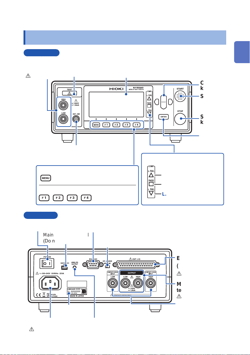
1.2 Parts Names and Functions
Parts Names and Functions
Front panel
Measurement
terminals (p. 24)
Refer to p. 10.
EXT.SW terminal (p. 109)
For 9299 Switched Probe
MENU key
Switching of pages
F keys
Rear panel
TEST lamp
(p. 49)
Selection of settings
displayed on the
screen
Display screen
(Monochrome graphical LCD)
COMP lamps (p. 44)
U.FAIL
Upper limit value ≤ Measured value
PASS
Within judgment standard
L.FAIL
Lower limit value ≥ Measured value
Cursor
keys
START
key
STOP
key
ENTER
key
1
2
3
4
5
6
7
Power switch (p. 26)
Maintenance terminal
(Do not use.)
Manufacturer’s
serial No.
Power inlet (p. 23)
Refer to p. 10.
RS-232C connector (p. 115)
EXT.I/O mode switch (NPN/PNP) (p. 82)
Left: Current sink (NPN), Right: Current source (PNP)
EXT.I/O terminal
(p. 82)
Measurement
terminals (p. 24)
Contact check
terminals (p. 58)
Analog output terminal (p. 105)
For 9094 Output Cord
Refer to p. 11.
Refer to p. 11.
8
9
10
Appx. Ind.
17
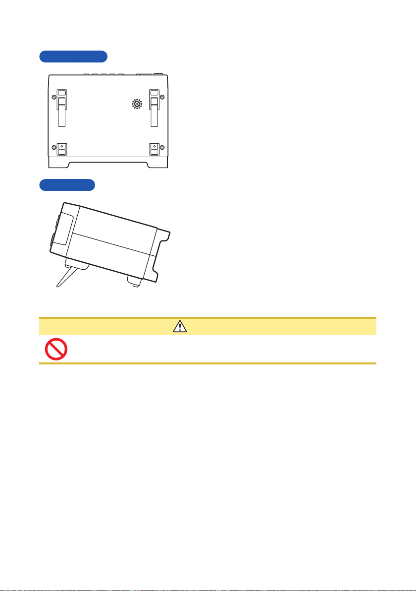
Parts Names and Functions
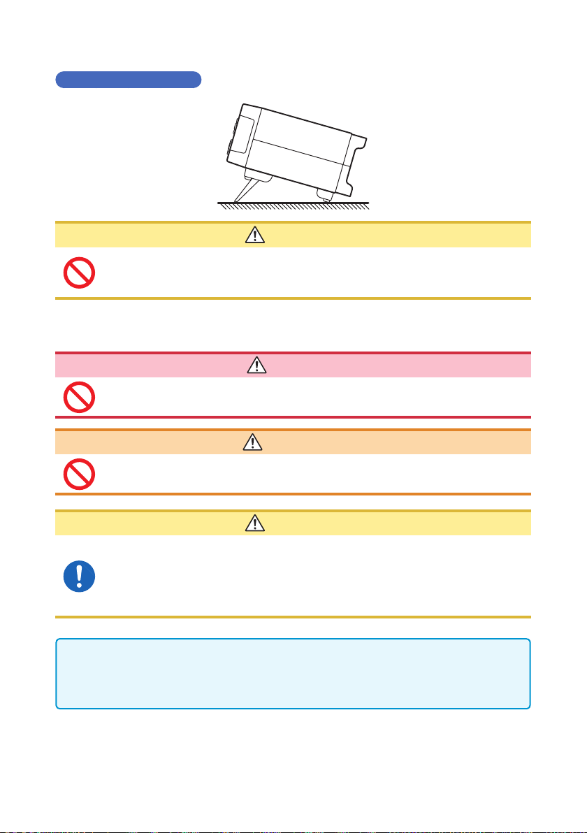
Bottom panel
Side panel
This instrument can be rack-mounted.
Refer to “Appx. 7 Rack Mounting” (p. Appx.10).
The parts removed from this instrument
should be stored in a safe place for future
reuse.
When using the stand
Extend the legs all the way.
Make sure to extend both legs of the stand.
When collapsing the stand
Do not collapse the stand partway. Be sure to
collapse it all the way.
18
CAUTION
When the instrument is set on the stand, do not apply a strong force from
above. Doing so may damage the stand.
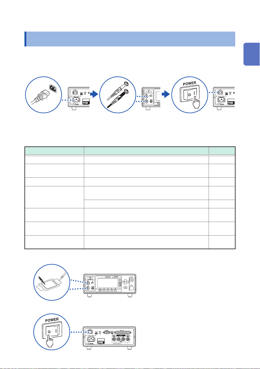
1.3 Measurement Workow
Measurement Workow
Be sure to refer to “Usage Notes” (p. 7) before use.
Preparing for measurement (p. 23)
1
(Use the measurement terminals on the rear
panel in case of 4-terminal measurements.)
Checking before measurement (p. 27)
2
Setting measurement conditions (p. 33)
3
Item Description Reference
Test voltage
Resistance range
Measurement speed
Test duration
Comparator
(upper/lower limit values)
Test mode
Beep sound
Select from 25 V to 1000 V.
Select either manual range (2 M
2000 M
Select either FAST or SLOW.
Set how long to apply the test voltage (test duration
function).
Set the response time.
Set the upper/lower resistance values.
Select from continuous mode, FAIL STOP mode, PASS
STOP mode, or forced termination judgment mode.
Set the conditions to announce the judgment result
with a beep sound.
, 4000 MΩ) or auto range.
Ω
, 20 MΩ, 200 MΩ,
Ω
p. 34
p. 36
p. 38
p. 39
p. 41
p. 44
p. 46
p. 47
1
2
3
4
5
6
7
8
Performing measurement
4
Turning off the power after use
5
9
10
Appx. Ind.
19
Screen Conguration and Operation Overview
1.4 Screen Conguration and Operation Overview
This instrument consists of a measurement screen and various settings screens.
The screen examples in this manual appear reversed (black on white) for best
visibility. The instrument screens, however, can actually be displayed only as white
characters on a black background.
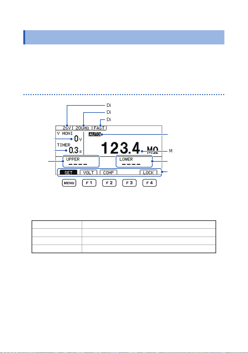
Measurement screen
Displays the test voltage setting.
Displays the resistance range setting.
Displays the measurement speed setting.
Voltage
monitor value
Test duration
Upper limit
value
F key set items
SET Moves to the Settings screen. (p. 33)
VOLT Moves to the Test Voltage Settings screen. (p. 34)
COMP Moves to the Comparator Settings screen. (p. 44)
LOCK Executes the key lock function. (p. 65)
The auto range is set.
(Nothing is displayed in
the manual range.)
Measured value
Lower limit value
Moves to various settings
screens.
Use the F keys at the
bottom of the screen to
select a screen.
20
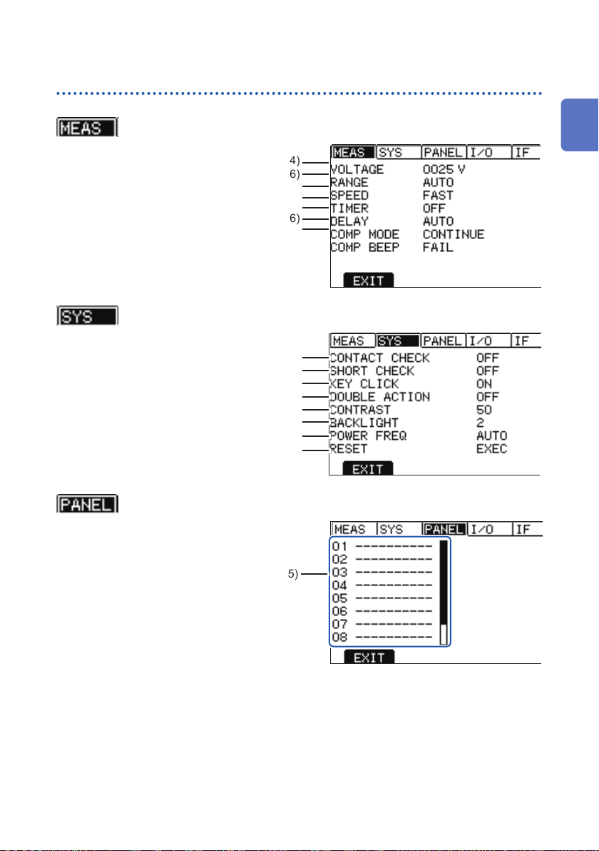
Settings screen
Screen Conguration and Operation Overview
(MEAS screen)
Setting the test voltage (p. 34)
Setting the measurement speed (p. 38)
(SYS screen)
Setting the contact check function (p. 56)
Setting the short circuit check function (p. 60)
Setting the double action function (p. 68)
Setting the screen contrast (p. 69)
Setting the power frequency (p. 71)
(PANEL screen)
Setting the range (p. 36)
Setting the test duration (p. 39)
Setting the response time (p. 41)
Setting the test mode (p. 46)
Setting the beep sound (p. 47)
Setting the key beeper (p. 67)
Setting the backlight (p. 70)
Initializing the system (p. 72)
1
2
3
4
5
6
7
Setting the panel save/panel load (p. 75)
8
9
10
Appx. Ind.
21
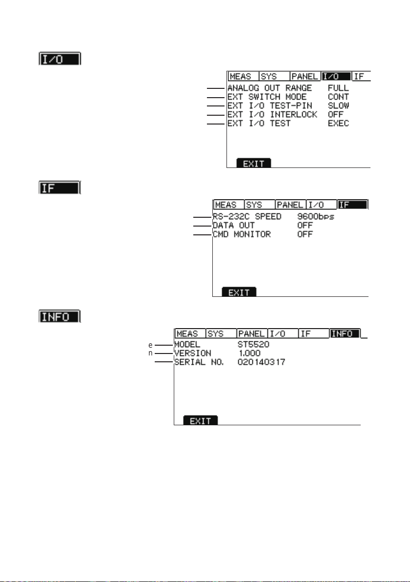
Screen Conguration and Operation Overview
(I/O screen)
Setting the analog output range (p. 104)
Setting the Switched Probe operation (p. 108)
Setting the test signal OFF timing (p. 101)
Setting the INTERLOC test function (p. 108)
Setting the EXT.I/O test function (p. 103)
(IF screen)
Setting the RS-232C interface (p. 114)
Setting the data output function (p. 117)
Setting the communications monitor function
(p. 120)
(INFO screen)
Manufacturer's serial No.
22
Model name
Version
 Loading...