

Page 1
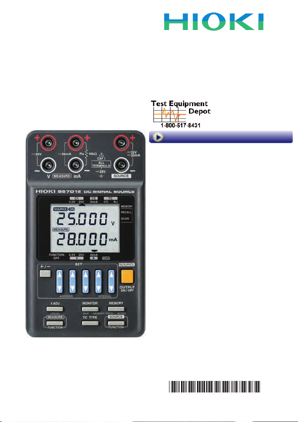
SS7012
Instruction Manual
DC SIGNAL SOURCE
Visit us at www.TestEquipmentDepot.com
99 Washington Street
Melrose, MA 02176
Phone 781-665-1400
Toll Free 1-800-517-8431
Mar. 2015 Revised edition 8
SS7012A981-08 15-03H
EN
* 6 0 0 2 8 7 5 1 8 *
Page 2

Contents
Introduction .......................................................................... 1
Confirming Package Contents ............................................. 2
Safety Information ................................................................ 3
Operating Precautions ......................................................... 7
Chapter 1 Overview 13
1.1 Product Overview .............................................. 13
1.2 Features ............................................................14
1.3 Names and Functions of Parts .......................... 15
1.4 Sourcing and Measurement Flowchart ............. 23
Chapter 2 Sourcing, Measurement and
Loop test Preparation 25
2.1 Supplying Power ............................................... 25
Installing or Replacing the Batteries .................. 25
Connecting the AC Adapter (Option) ................ 27
2.2 Connecting the Input Cord and the Test Lead .. 28
2.3 Turning the Power On and Off .......................... 33
2.4 Pre-Operation Inspection ..................................34
Chapter 3 Sourcing 37
3.1 Sourcing Example ............................................. 38
3.2 Sourcing Constant Voltage and
Constant Current ...............................................39
3.3 Sourcing Thermoelectromotive Force ............... 43
3.4 0°C Check of the
100 Ω Resistance Thermometer ....................... 50
3.5 Output Monitor Function .................................... 51
3.6 Memory Source Function .................................. 54
Saving setting value to memory ........................ 55
Recall sourcing .................................................. 59
SS7012A981-08
i
Page 3

ii
Scan sourcing ....................................................61
Initializing setting values ....................................63
3.7 When setting value is flashing ...........................65
Chapter 4 Measurement 67
4.1 Measurement Example ......................................67
4.2 Voltage Measurement and
Current Measurement ........................................68
4.3 Temperature Measurement ...............................71
Chapter 5 Loop Test 75
5.1 Loop Test Overview ...........................................75
5.2 Testing a Distributor (4-20 mA) .........................76
5.3 Testing a two-wire transmitter ...........................79
Chapter 6 Other Function 81
6.1 USB Communication Function ..........................81
Chapter 7 Specifications 83
7.1 General Specifications .......................................83
7.2 Accuracy ............................................................86
Chapter 8 Maintenance and Service 91
8.1 Troubleshooting .................................................91
8.2 Replacing the Circuit Protection Fuse ...............94
8.3 Cleaning ............................................................96
8.4 Error Indication ..................................................97
8.5 Other Indication .................................................97
8.6 When calibrating the instrument ........................98
Index Index 1
Page 4

Introduction
Introduction
Thank you for purchasing the HIOKI Model SS7012 DC Signal
Source. To obtain maximum performance from the instrument,
please read this manual first, and keep it handy for future reference.
1
Page 5
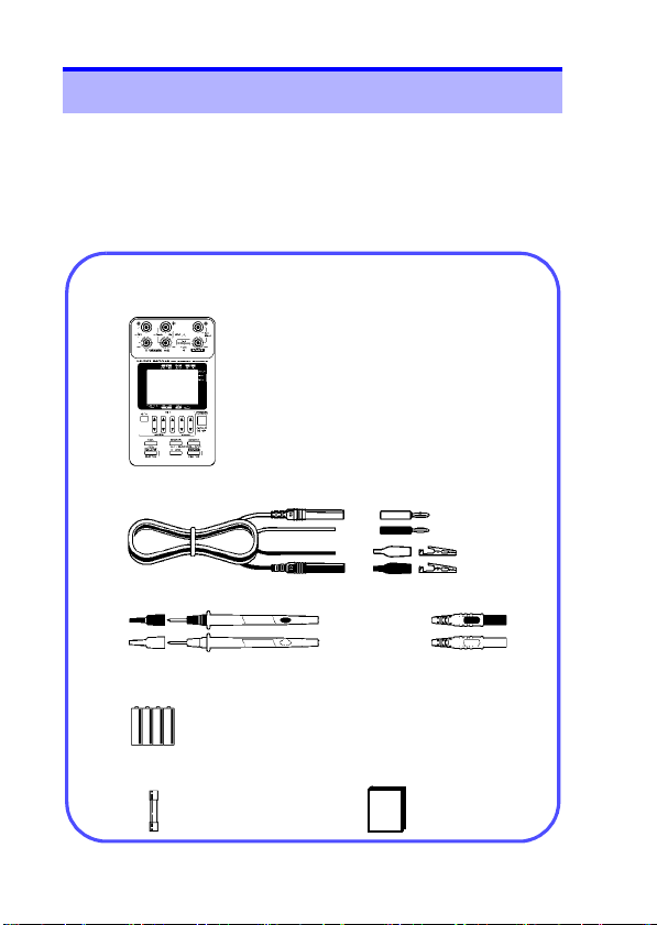
Confirming Package Contents
Confirm that these contents are provided.
SS7012 DC Signal Source (1)
Instruction Manual (1)
9168 Input Cord (1 set)
LR6 alkaline batteries (4)
L9170-10 Test lead (1 set)
Spare fuse (1)
2
Confirming Package Contents
When you receive the instrument, inspect it carefully to ensure
that no damage occurred during shipping. In particular, check
the accessories, panel switches, and connectors. If damage is
evident, or if it fails to operate according to the specifications,
contact your dealer or Hioki representative.
Page 6

Safety Information
Options
9184 Temperature Probe (reference junction compensation)
9380 Carrying Case (Holds main unit only, soft case)
9782 Carrying Case (Holds options, hard case)
9445-02 AC Adapter (For Japan, US, and Canada)
9445-03 AC Adapter (For EU)
SS9000 Communication Package
(Includes USB cable and USB driver software)
Safety Information
This instrument is designed to comply with IEC 61010
Safety Standards, and has been thoroughly tested for
safety prior to shipment. However, mishandling during use
could result in injury or death, as well as damage to the
instrument. Using the instrument in a way not described in
this manual may negate the provided safety features.
Be certain that you understand the instructions and precautions in the manual before use. We disclaim any
responsibility for accidents or injuries not resulting directly
from instrument defects.
3
Page 7
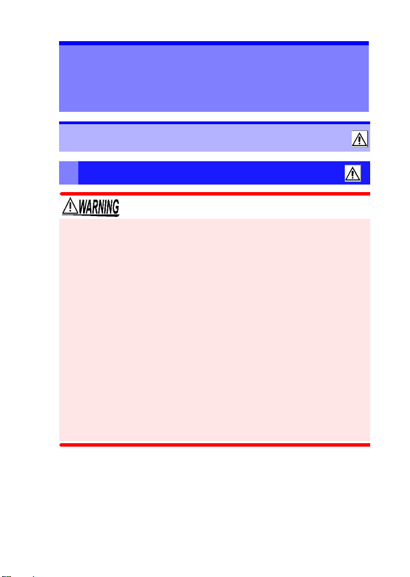
Safety Information
4
This manual contains information and warnings essential for
safe operation of the instrument and for maintaining it in safe
operating condition. Before using it, be sure to carefully read the
following safety precautions.
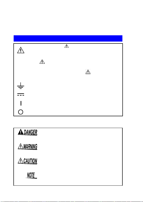
Safety Symbols
In the manual, the symbol indicates particularly
important information that the user should read
before using the instrument.
The symbol printed on the instrument indicates
that the user should refer to a corresponding topic in
the manual (marked with the symbol) before
using the relevant function.
Indicates a grounding terminal.
Indicates DC (Direct Current).
Indicates the ON side of the power switch.
Indicates the OFF side of the power switch.
The following symbols in this manual indicate the relative importance of cautions and warnings.
Indicates that incorrect operation presents
an extreme hazard that could result in serious injury or death to the user.
Indicates that incorrect operation presents a
significant hazard that could result in serious
injury or death to the user.
Indicates that incorrect operation presents a
possibility of injury to the user or damage to
the instrument.
Indicates advisory items related to performance or correct operation of the instrument.
Page 8
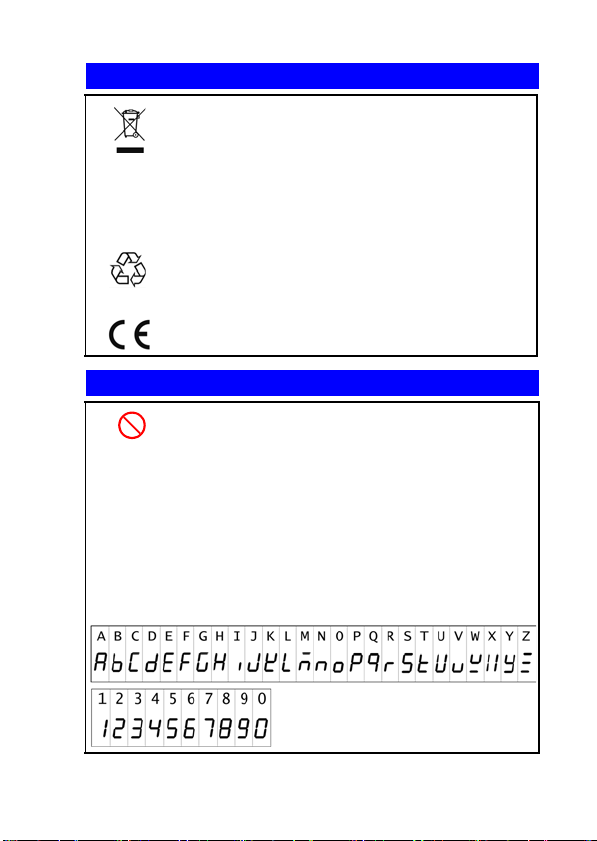
Symbols for Various Standards
WEEE marking:
This symbol indicates that the electrical and
electronic appliance is put on the EU market
after August 13, 2005, and producers of the
Member States are required to display it on the
appliance under Article 11.2 of Directive 2002/
96/EC (WEEE).
This is a recycle mark established under the
Resource Recycling Promotion Law (only for
Ni-MH
Japan).
This symbol indicates that the product conforms
to regulations set out by the EC Directive.
Other Symbols
Indicates a prohibited action.
Safety Information
5
(p. #)
[ ] The names of setting objects are indicated by
OUTPUT
(Bold char-
acters)
The screen of this instrument displays characters in the following manner.
Indicates the location of reference information.
square brackets [ ].
Bold alphanumeric characters in this manual indicate key labels.
Page 9
Safety Information
6
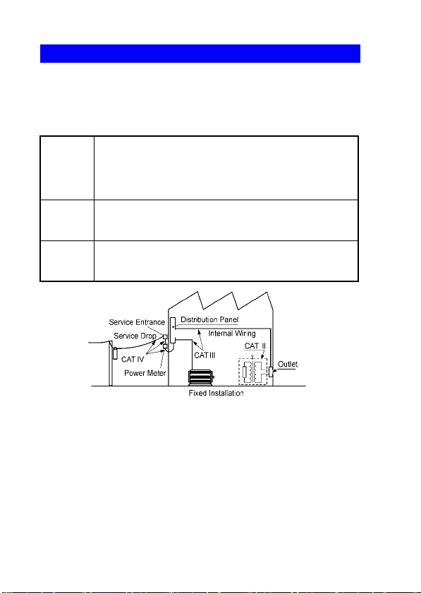
Measurement categories
To ensure safe operation of measurement instruments IEC
61010 establishes safety standards for various electrical environments, categorized as CAT II to CAT IV, and called measurement categories.
Primary electrical circuits in equipment connected to an AC
CAT II
CAT III
CAT IV
Using a measurement instrument in an environment designated
with a higher-numbered category than that for which the instrument is rated could result in a severe accident, and must be
carefully avoided.
Use of a measurement instrument that is not CAT-rated in CAT II
to CAT IV measurement applications could result in a severe
accident, and must be carefully avoided.
electrical outlet by a power cord (portable tools, household
appliances, etc.)
CAT II covers directly measuring electrical outlet receptacles.
Primary electrical circuits of heavy equipment (fixed installations) connected directly to the distribution panel, and
feeders from the distribution panel to outlets.
The circuit from the service drop to the service entrance,
and to the power meter and primary overcurrent protection
device (distribution panel).
Page 10
Operating Precautions
Operating Precautions
Follow these precautions to ensure safe operation and to obtain
the full benefits of the various functions.
Preliminary Checks
Before using the instrument for the first time, verify that it operates normally to ensure that no damage occurred during storage
or shipping. If you find any damage, contact your dealer or Hioki
representative.
Instrument Installation
Operating temperature and humidity: 0 to 40°C at 80%RH or
less (non-condensating)
Temperature and humidity range for guaranteed accuracy:
23±5°C, 80%RH or less (non-condensating)
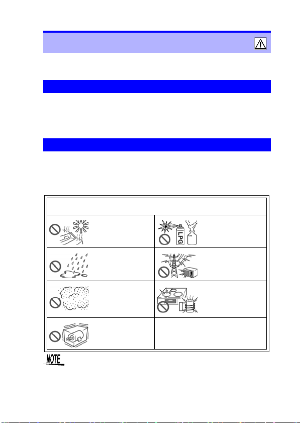
Avoid the following locations that could cause an accident or damage
to the instrument.
Exposed to direct
sunlight
Exposed to high temperature
Exposed to liquids
Exposed to high humidity or condensation
Exposed to high levels of particulate dust
In the presence of corrosive or explosive
gases
Exposed to strong
electromagnetic fields
Near electromagnetic
radiators
Near electromagnetic
radiators (e.g., highfrequency induction
heating systems and
IH cooking utensils)
7
Subject to vibration
Correct measurement may be impossible in the presence of strong magnetic fields, such as near transformers and high-current conductors, or in the presence of
strong electromagnetic fields such as near radio transmitters.
Page 11

Operating Precautions
8
Handling the Instrument
The maximum rated voltage between input terminals and
ground is 30 VAC/ 60 VDC. Attempting to measure voltages
exceeding 30 VAC/ 60 VDC with respect to ground could
damage the instrument and result in personal injury.
• This instrument is designed for safe operation only at low
voltage. Ensure that no more than 60 V is present
between any terminal and ground, and that the potential
difference between any two terminals does not exceed 60
V. The instrument cannot be guaranteed in an overrange
situation, such as due to an inadvertent electric shock or
faulty insulation, and we cannot accept responsibility for
any consequences that might occur from misuse.
• The output terminals and the voltage and current input
terminals (terminals for the standard resistor) are all isolated. Before connecting the terminals, ensure that the
target device will not provide excessive output to, or
require excessive input from, the terminals. The instrument cannot be guaranteed in an overrange situation,
such as due to an inadvertent electric shock or faulty
insulation, and we cannot accept responsibility for any
consequences that might occur from misuse.
• Ensure that the input does not exceed the maximum input
voltage or current to avoid instrument damage, short-circuiting and electric shock resulting from heat building.
• Do not allow the instrument to get wet, and do not take
measurements with wet hands. This may cause an electric shock.
• The case is not hermetically sealed for protection against
explosion, so do not use in a flammable atmosphere.
Page 12
Operating Precautions
• When the power is turned off, do not apply voltage to the voltage input terminals. Doing so may damage the instrument.
• To avoid damage to the instrument, protect it from physical
shock when transporting and handling. Be especially careful
to avoid physical shock from dropping.
• If this instrument has been vibrated or impacted, restart it
before use.
• Before sourcing or measurement, make sure of the function
position. If current or voltage in excess of sourcing or measurement range is input, the instrument may be damaged.
• Note that the instrument may be damaged if the applied voltage or current exceeds the measurement range.
• If output is impossible when is displayed which indicates
outputting, set to with OUTPUT ON/OFF key and set
output to ON again.
• To avoid corrosion and damage to this instrument from battery
leakage, remove the batteries from the instrument if it is to be
stored for a long time.
To avoid problems with battery operation, remove the
batteries from the instrument if it is to be stored for a
long time.
9
Page 13
Operating Precautions
10
Handling the Cords
• Before using the instrument, make sure that the insulation on the test lead and input cord is undamaged and
that no bare conductors are improperly exposed. Using
the instrument in such conditions could cause an electric
shock, so contact your dealer or Hioki representative for
repair.
• Use the 9168 Input Cord with DC 28 V or less.
If this level is exceeded, electric shock may occur.
• Always turn both devices OFF when connecting and disconnecting an interface connector. Otherwise, an electric
shock accident may occur.
• To avoid breaking the test lead and input cord, do not bend or
pull them.
• For safety reasons, when taking measurements, only use the
L9170-10 Test lead provided with the instrument.
Page 14
Operating Precautions
11
Handling the AC Adapter and the Nickel Hydride
Batteries
• Turn the instrument off before connecting the AC adapter
to the instrument and to AC power.
• Use only the supplied Model 9445-02 AC Adapter or
Model 9445-03 AC Adapter. AC adapter input voltage
range is 100 to 240 VAC (with ±10% stability) at 50/60 Hz.
To avoid electrical hazards and damage to the instrument,
do not apply voltage outside of this range.
• To avoid damaging the power cord, grasp the plug, not the
cord, when unplugging it from the power outlet.
The nickel hydride battery is subject to self-discharge.
Be sure to charge the nickel hydride batteries before initial use. If the battery capacity remains very low after
correct recharging, the useful battery life is at an end.
Page 15
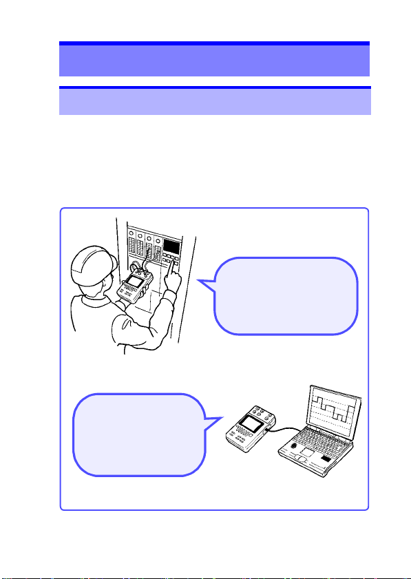
1.1 Product Overview
Two-wire transmitter and
distributor tests (4-20mA)
can be easily performed.
(Loop tests)
Source waveforms can
be freely programmed
through communication with a computer.
13
Overview Chapter 1
1.1 Product Overview
This instrument is a compact DC signal source (calibrator).
It can perform maintenance or loop tests of instrumentation systems and can be operated from a computer via a USB cable.
Furthermore, it can calibrate thermometers and measure DC
voltage and DC current.
Page 16

1.2 Features
14
1.2 Features
Source function (p.39) (p.43)
Sourcing DC voltage from -25.000 V to +25.000 V (minimum
resolution 100 μV), and DC current from -25.000 mA to
25.000 mA (minimum resolution 1 μA). Sourcing thermoelectromotive force by setting temperature (thermocouples: K, E,
J, T, R, S, B, N; JIS C1602-1995, IEC 584).
Measure function (p.68) (p.71)
Measurement of DC voltage from -28.000 V to +28.000 V
(minimum resolution 100 μV), and of DC current from -
28.000 mA to 28.000 mA (minimum resolution 1 μA). Temperature measurement from -25°C to 80°C with the optional
Model 9184 Temperature Probe.
Loop test (p.75)
The output of this instrument is bipolar and it can sink current. Therefore, loop test in the instrumentation system is
possible.
Output monitor function (p.51)
This function monitors the applied current of the constant
voltage source.
This function monitors the applied voltage of the constant
current source.
This function monitors the reference junction temperature of
the thermoelectromotive force source.
Memory source function (p.54)
Up to 20 units of source data (settings) for each function can
be saved to memory. Settings saved to memory can be
sourced in recall source mode or scan source mode.
AC power is not required for operation
Common LR6 alkaline batteries or nickel hydride batteries
support use in situations where AC power is not available.
Continuous long-term operation
The optional Model 9445-02 AC Adapter or 9445-03 AC
Adapter allows continuous long-term operation.
Page 17
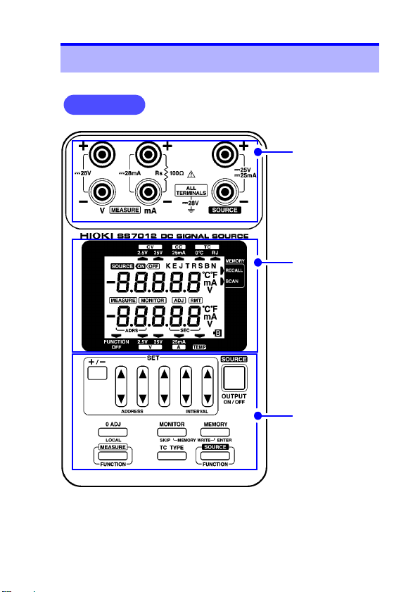
1.3 Names and Functions of Parts
Front panel
Display
(p.19)
Operation Keys
(p.21)
Ter m ina ls
(p.18)
1.3 Names and Functions of Parts
15
Page 18
1.3 Names and Functions of Parts
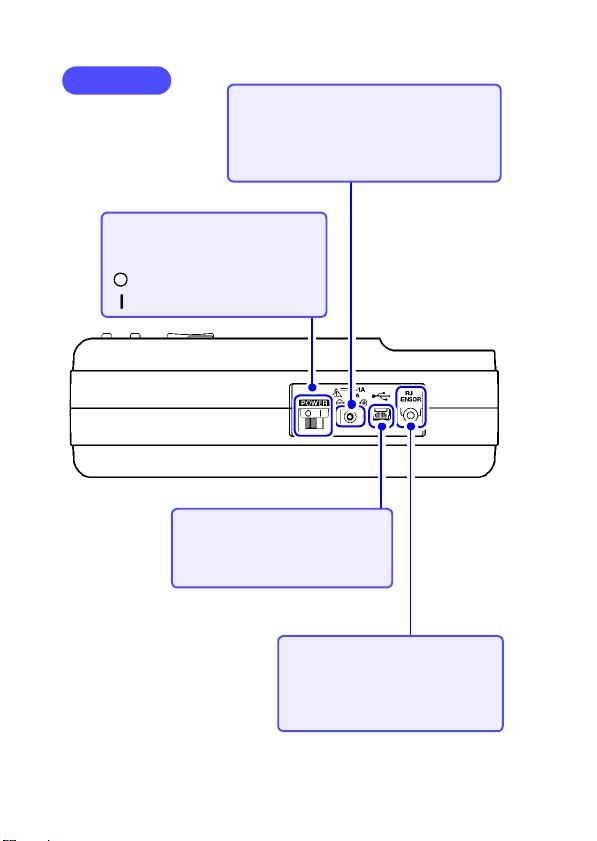
Right side
RJ sensor terminal
Connect the optional Model 9184
Temperature Probe (reference
junction compensation).
(p.30) (p.71)
USB port
The SS7012 can communicate
with a computer via a USB cable.
(p.81)
AC adapter terminal
Connect the optional Model 9445-02 AC
Adapter or 9445-03 AC Adapter.The input
voltage range is 9 V DC±10% and the
adapter has a positive center pin. (p.27)
Power switch
Turns the power for the instrument on or off. (p.33)
: Power switch OFF
: Power switch ON
16
Page 19
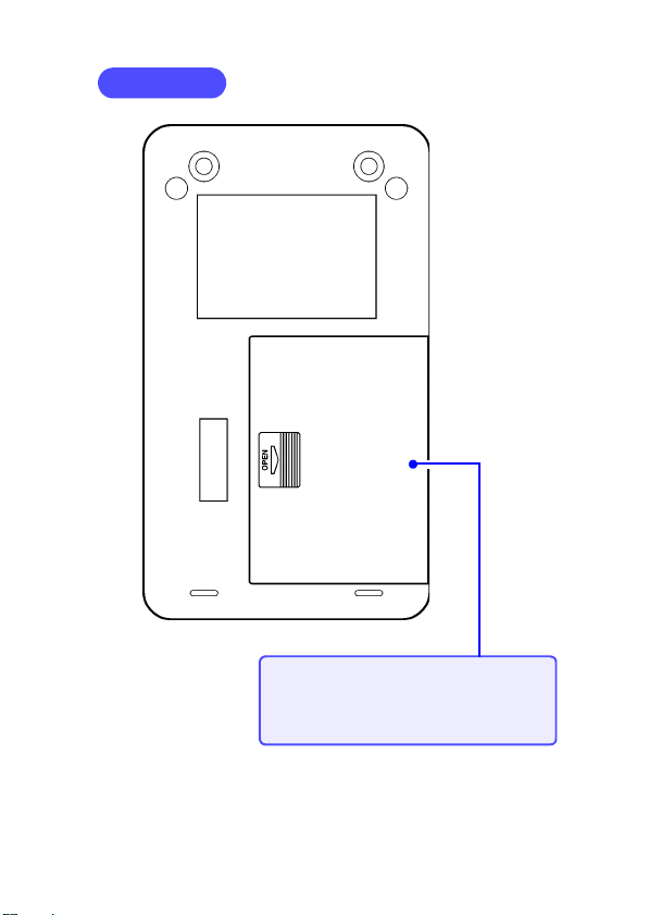
Rear panel
Battery cover
Open this battery cover to install the LR6
alkaline batteries or the nickel hydride batteries. (p.25)
1.3 Names and Functions of Parts
17
Page 20
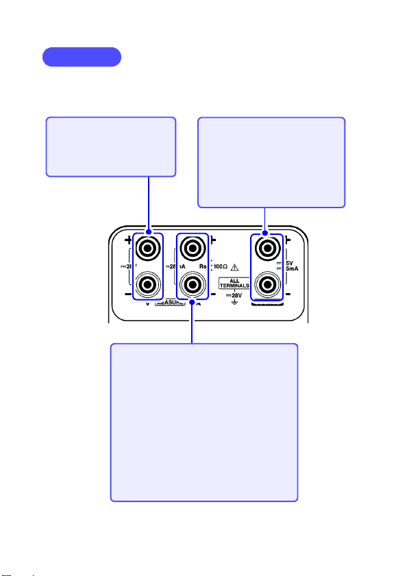
18
Termi nals
Voltage input terminal
Inputs voltage for voltage
measurement. Input resistance is about 1 MΩ.
Current input terminal/
Terminal for the standard resistor
Current input
Inputs current for current measurement
function. The SS7012 has built-in input
protection fuse. The input resistance of
current detection and input protection fuse
is about 30 Ω.
Standard resistor
When current measurement function is
off, a 100 Ω standard resistor is connected
for the 0°C check of the 100 Ω standard
resistance thermometer.
Output terminal
When output is on, the setting
value will be output. This terminal is shorted with about 50 kΩ
resistance when output is off.
The SS7012 has built-in output
protection fuse.
1.3 Names and Functions of Parts
Page 21
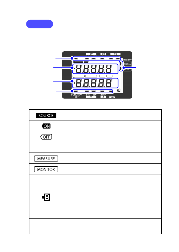
1.3 Names and Functions of Parts
Display
Various values are displayed, including functions, source values, measurement values, monitor values, thermocouples, polarity, units, output
status and warnings.
Upper values
Lower values
Upper triangles
Lower triangles
Right side
triangles
19
SOURCE ON OFF
MEASURE
K
EJTRSBN
MONITOR ADJ RMT
C
mA
C
mA
V
V
Indicates values and settings related to source functions.
Indicates that the setting for the source function is
being output.
Indicates that the setting for the source function is
not being output.
K/ E/ J/ T/ R/
S/ B/ N
Indicates the specified thermocouple type.
Indicates values and settings related to measure
functions.
Indicates that the output monitor function has been
set. (p.51)
This is the battery indicator (Battery low warning).
When this indicator starts flashing, either exchange
the batteries or connect the AC adapter.
When this indicator is flashing, output cannot be set
to ON. (If the SS7012 is outputting when the indica-
Flashing of
setting value
tor starts flashing, output continues until the output
is set to OFF.
Furthermore, the accuracy of measurement values
cannot be guaranteed.
The setting value flash when it is not being output.
(p.65) If a setting value is flashing, press the
OUTPUT key to set the output to OFF.
Page 22
1.3 Names and Functions of Parts
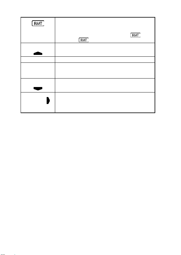
Upper triangles
Lower triangles
Right side
triangles
20
Indicates that the SS7012 is in remote control
mode. The instrument cannot be operated by the
keys. Use the LOCAL key to enable key operation.
If the USB cable is removed when the is displayed, the indicator does not turn off.
Indicates the specified source function.
Upper values Displays setting value for the source functions.
Lower values
Displays the measurement values of the measure
function and the address and sourcing time interval
of the memory source function.
Indicates the specified measure function.
Indicates the specified source mode.
Off : Normal source mode
RECALL : Recall source mode
SCAN : Scan source mode
Page 23
1.3 Names and Functions of Parts
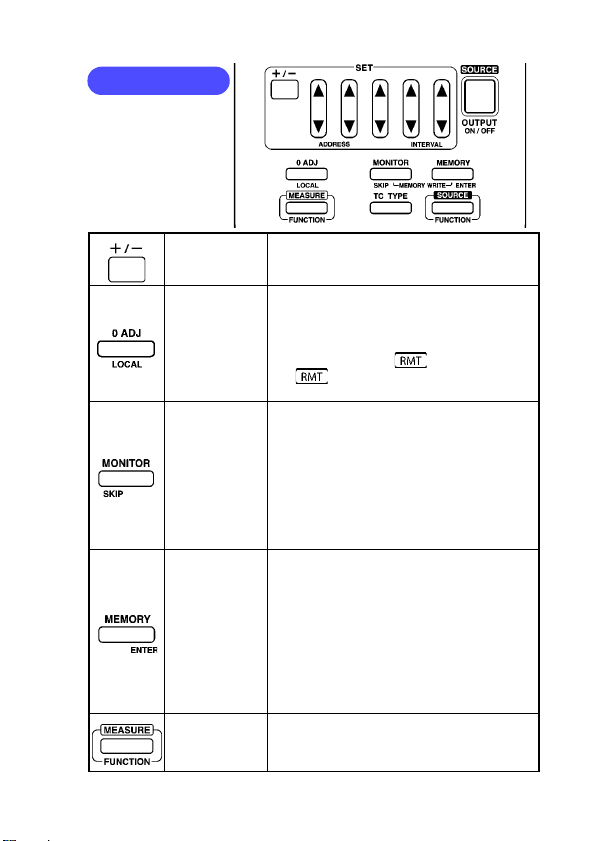
Operation Keys
21
+/- key
0 ADJ/
LOCAL key
MONITOR/
SKIP key
MEMORY/
ENTER key
MEASURE
FUNCTION
key
Selects the polarity of the output setting
value.
1. Possible to return the display to
"00000" in voltage measurement function ([V:2.5V], [V:25V]), or current mea-
surement function ([A: 25mA]).
2. If pushed while is displayed, the
indicator goes out and local con-
trol is possible.
1. Toggles the measure function and output monitor function. (p.51)
2. When writing to memory in the memory
source function, this key sets a skip
setting. (p.55)
3. When pushed simultaneously with the
MEMORY/ENTER key, toggles the
source function and the memory write
mode of the source function. (p.55)
1. Toggles between the normal source,
recall source, and scan source. (p.59)
(p.61)
2. When writing to memory in the memory
source function, this key confirms the
setting value. (p.55)
3. When pushed simultaneously with the
MONITOR/SKIP key, toggles the
source function and the memory write
mode of the source function. (p.55)
Sets the measure function for the instrument.
Page 24
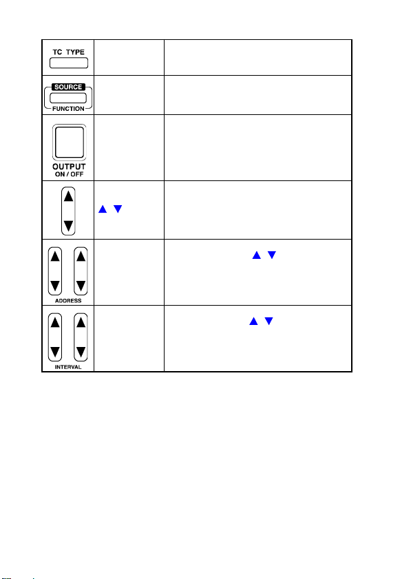
1.3 Names and Functions of Parts
22
TC TYPE key
SOURCE
FUNCTION
key
Sets the thermocouple type in the thermoelectromotive force source function
([TC:0°C], [TC:RJ]).
Sets the source function for the instrument.
OUTPUT
ON/OFF key
/ key
ADDRESS
key
INTERVAL
key
Switches the output on or off in the source
function.
This key can be used as the start/stop for
memory source function.
The digit increases or decreases by one
count each time the key is pressed. Press
and hold the key to change the digit continuously.
These are the two / keys on the left
of the arrow key group.
In the memory source function, these keys
specify the address.
These are the two / keys on the right
of the arrow key group.
In the memory source function, these keys
specify the sourcing time interval.
Page 25
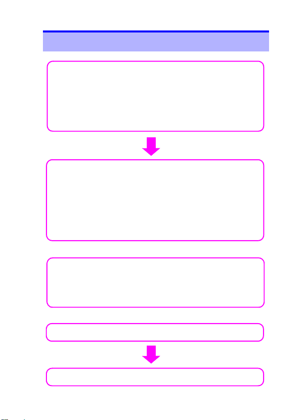
1.4 Sourcing and Measurement Flowchart
1. Inspections before switching on the power and
using the instrument
Connecting the AC Adapter (p.27)
Installing the Batteries (p.25)
Turning the Power On (p.33)
Pre-Operation Inspection (p.34)
2. Sourcing
Constant voltage (p.39)
Constant current (p.39)
Thermoelectromotive force (p.43)
Standard register (100 Ω) (p.50)
Output monitor function (p.51)
Memory source function (p.54)
2. Measurement
Voltage (p.68)
Current (p.68)
Temperature (p.71)
3. Turning the Power Off (p.33)
2. Loop test (p.75)
or
or
1.4 Sourcing and Measurement Flowchart
23
Page 26
2.1 Supplying Power
25
Sourcing, Measurement and Loop test Preparation Chapter 2
2.1 Supplying Power
Installing or Replacing the Batteries
• Use the common LR6 alkaline batteries or the common
nickel hydride batteries.
• To avoid electric shock, turn off the power switch and disconnect the test leads or input cords from the target
device before replacing the batteries.
• After replacing the batteries, replace the cover before
using the instrument.
• Do not mix old and new batteries, or different types of
batteries. Also, be careful to observe battery polarity during installation. Otherwise, poor performance or damage
from battery leakage could result.
• Battery may explode if mistreated. Do not short-circuit,
disassemble or dispose of in fire. Do not recharge alkaline batteries. Handle and dispose of batteries in accordance with local regulations.
Page 27
2.1 Supplying Power
26
• Do not use the LR6 alkaline batteries together with the nickel
hydride batteries.
• To avoid corrosion and damage to this instrument from battery
leakage, remove the batteries from the instrument if it is to be
stored for a long time.
• The indicator flashes when the remaining battery
capacity is low. In this case, the instrument's reliability
is not guaranteed. Replace the battery immediately.
• When the nickel hydride batteries have not been used
for a long time and are not repeat charge and discharge, the device may not operate normally. (This
may also occur immediately after purchase.)
• Please use only LR6 alkaline batteries or nickel
hydride (HR6) batteries. Please do not use manganese, oxyride batteries, etc.
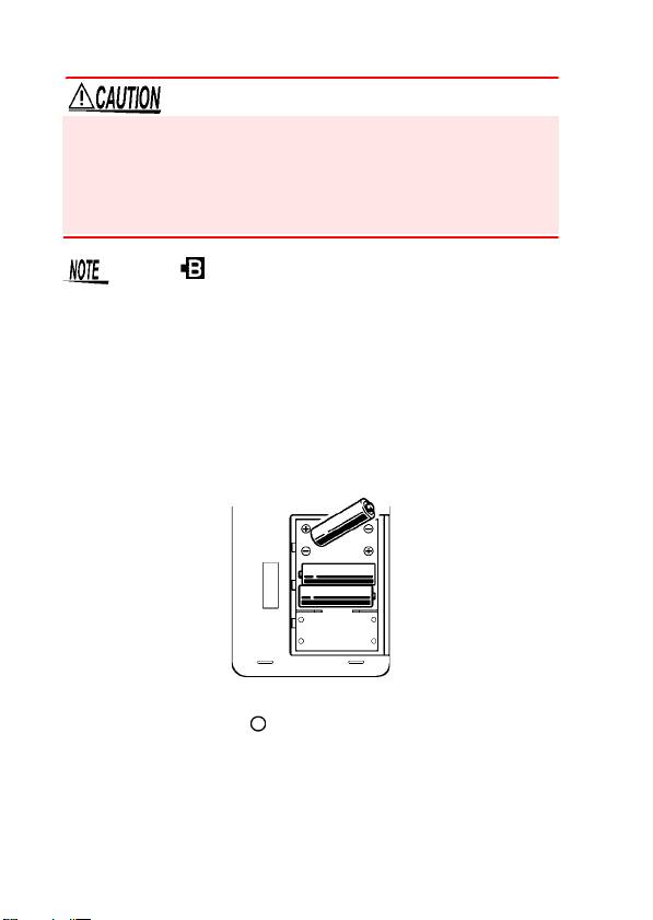
Before installing or exchanging batteries, turn the
1.
power switch off ( ).
Open the battery cover and install four batteries with
2.
the correct polarity.
Be sure to close the battery cover.
3.
Page 28
2.1 Supplying Power
27
Connecting the AC Adapter (Option)
• Turn the instrument off before connecting the AC adapter
to the instrument and to AC power.
• Use only the supplied Model 9445-02 AC Adapter or
Model 9445-03 AC Adapter. AC adapter input voltage
range is 100 to 240 VAC (with ±10% stability) at 50/60 Hz.
To avoid electrical hazards and damage to the instrument,
do not apply voltage outside of this range.
Turn the power switch off ( ).
1.
Connect the 9445-02 AC Adapter or the 9445-03 AC
2.
Adapter output plug to the AC adapter terminal for the
instrument. (The input voltage range is 9 VDC±10%
and the adapter has a positive center pin)
After making sure that the voltage of the power supply
3.
being used matches the supply voltage of the AC
adapter, put the plug in the outlet.
Page 29
2.2 Connecting the Input Cord and the Test Lead
28
2.2 Connecting the Input Cord and
the Test Lead
The SS7012 has voltage input terminal, current input terminal
(terminal for the standard resistor) and output terminal.
In addition, RJ sensor terminal is provided for temperature measurement.
To prevent an electric shock accident, confirm that the white or
red portion (insulation layer) inside the cable is not exposed. If a
color inside the cable is exposed, do not use the cable.
Removable sleeves are attached to the metal pins at
the ends of the test leads. The test leads can also be
used with the sleeves removed.
Removing and attaching the sleeves
The tips of the metal pins are sharp, so take care not to injure
yourself.
Removing the sleeves
Gently hold the bottom of the sleeves and pull the sleeves off.
Safely store the removed sleeves so as not to lose them.
Attaching the sleeves
Insert the metal pins of the test leads into the holes of the
sleeves, and firmly push them all the way in.
Page 30
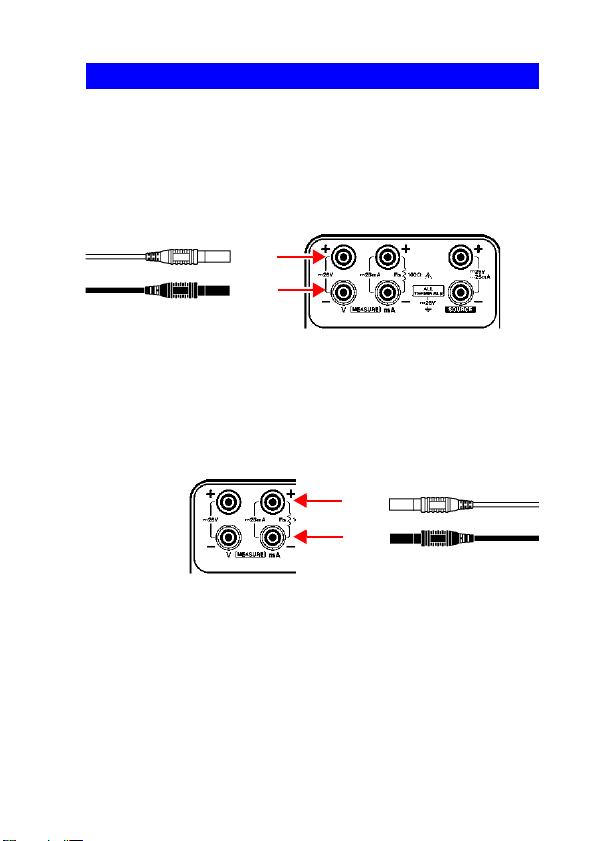
2.2 Connecting the Input Cord and the Test Lead
Voltage measurement
Connect the L9170-10 Test lead to the voltage input terminal.
Connect the red and black connectors to the + and - input terminals,
respectively.
Input only voltage to the voltage input terminal.
L9170-10 Test lead
Current measurement
Connect the L9170-10 Test lead to the current input terminal.
Connect the red and black connectors to the + and - input terminals,
respectively.
Input only current to the current input terminal.
L9170-10 Test lead
(red)
(black)
(red)
(black)
Connecting Method
29
Page 31

2.2 Connecting the Input Cord and the Test Lead
[TC:RJ] sourcing, Temperature measurement
Connect the optional 9184 Temperature Probe to the
RJ sensor terminal.
9184 Temperature Probe
Sourcing
With the output off, connect the 9168 Input Cord to the
output terminal.
Connect the red and black connectors to the + and - output terminals,
respectively.
9168 Input Cord
(red)
(black)
0°C check for the 100 Ω resistance thermometers
Connect the 100 Ω standard resistance thermometer to
the terminal for the standard resistor.
(red)
(black)
30
Page 32

2.2 Connecting the Input Cord and the Test Lead
• This instrument is designed for safe operation only at low
voltage. Ensure that no more than 60 V is present
between any terminal and ground, and that the potential
difference between any two terminals does not exceed 60
V. The instrument cannot be guaranteed in an overrange
situation, such as due to an inadvertent electric shock or
faulty insulation, and we cannot accept responsibility for
any consequences that might occur from misuse.
• The output terminals and the voltage and current input
terminals (terminals for the standard resistor) are all isolated. Before connecting the terminals, ensure that the
target device will not provide excessive output to, or
require excessive input from, the terminals. The instrument cannot be guaranteed in an overrange situation,
such as due to an inadvertent electric shock or faulty
insulation, and we cannot accept responsibility for any
consequences that might occur from misuse. (For the
maximum value of the output voltage/current and voltage/
current input, refer to the specifications)
• To avoid electrical accidents, confirm that all connections
are secure. The increased resistance of loose connections can lead to overheating and fire.
• Be sure to connect the voltage input and current input terminals correctly. An incorrect connection could damage
or short circuit this instrument.
31
Page 33

2.2 Connecting the Input Cord and the Test Lead
32
• When switching the power on and off, remove the target
device from all terminals. Furthermore, always set the output
to OFF when connecting or disconnecting the output terminal
and target device. In either of these cases, failure to heed this
caution may result in damage to the instrument or to the target
device.
• Do not input current more than 25 mA DC to the terminal for
the standard resistor. Doing so may damage the resistor of the
instrument.
• Output terminal and current input terminal have circuit protection fuses. If the fuse is blown, output or current measurement
is impossible. Exchange the fuses before operation.
See: "8.2 Replacing the Circuit Protection Fuse" (p.94)
• When output is off, the output terminals are shorted
with a resistance of about 50 kΩ.
• Input resistance of the voltage input terminal is
approx. 1 MΩ and that of the current input terminal is
approx. 30 Ω.
Page 34

2.3 Turning the Power On and Off
33
2.3 Turning the Power On and Off
Before turning the instrument on, make sure the supply
voltage matches that indicated on the AC adapter. Connection to an improper supply voltage may damage the instrument or AC adapter and present an electrical hazard.
When switching the power on and off, remove the target device
from all terminals. Furthermore, always set the output to OFF
when connecting or disconnecting the output terminal and target device. In either of these cases, failure to heed this caution
may result in damage to the instrument or to the target device.
• If power switch is set to on ( ) for the instrument,
even when sourcing or measurement is not executed
current is still consumed. The lifetime of battery therefore shortens. The power switch should be turned off
( ) when unused.
• Because turning the power on or off places a load on
the instrument, wait at least 5 seconds before turning
the power off or on again.
• If the power doesn’t turn on when turning on the
power again, turn the power off and leave for more
than 5 seconds.
• The warm-up time of this instrument is 5 minutes.
Source values and measurement values can be
unstable within 5 minutes after turning the power on.
Page 35

2.4 Pre-Operation Inspection
Set the power switch to the " " position.
When the power switch is on, all settings
except memory are initialized to appear initial
screen after LCD display indications are all lit.
(ON)
Set the power switch to the " " position. Turn
off the power switch to go off the LCD display
indications.
(OFF)
Is the insulation of the test
lead or input cord to be used
damaged, or is bare metal exposed?
Is damage to the AC adapter
evident?
Is damage to the instrument
evident?
Do not use the instrument
if even one point of damage is found, as it can
cause electric shock.
If damage is evident, request repairs.
Yes
Yes
Yes
34
Turning Power On
Turning Power Off
2.4 Pre-Operation Inspection
Before using the instrument, verify that it operates normally to
ensure that no damage occurred during storage or shipping.
Instrument inspection
1.
Check the following points.
Page 36

Inspection at power on
The batteries may have
run out. Replace the batteries with new ones and
then check again.
No
Inspection
complete
Yes
The instrument may be damaged internally.
Request repairs.
No
An error is displayed
When the power is
switched on, does the
screen come on?
An error is
displayed
Yes
Use a powered outlet
and then check again.
Yes
The power cord may be
disconnected or the AC
adapter or instrument internals may be malfunctioning.
Request repairs.
Is a power failure
or another cause
preventing power
from reaching the
outlet?
No
Yes
Inspection
complete
The instrument may be damaged internally.
Request repairs.
No
When the power is
switched on, does the
screen come on?
An error is
displayed
2.
< When using batteries >
< When using AC adapter >
2.4 Pre-Operation Inspection
35
Page 37

37
Sourcing Chapter 3
Always inspect the instrument before sourcing.
See: "2.4 Pre-Operation Inspection" (p.34)
Always set the output to OFF when connecting or disconnecting
the output terminal and target device.
• If the display shows all zeros or is out of the setting
range while using the
disabled.
• Settings can be changed consecutively using the
/ keys. However, this operation cannot be used in
the following cases.
• When the changed setting exceeds the permitted
range
• When the changed setting exceeds “00000” and the
polarity changes (For example, when the setting is
“00001”, all keys and the right-most key can
be used.)
+/- keys, polarity changing is
Page 38

3.1 Sourcing Example
38
3.1 Sourcing Example
The SS7012 can source constant voltage, constant current, and
standard register.
Instead of the thermocouple, a voltage corresponding to a specified temperature can be sourced.
Constant voltage (CV) (p.39)
In [CV:2.5V], constant voltage can be sourced from -2.5 to +2.5 V with
the resolution of 100 µV.
In [CV:25V], constant voltage can be sourced from -25 to +25 V with
the resolution of 1 mV.
Constant current (CC) (p.39)
In [CC:25mA], constant current can be sourced from -25 to +25 mA
with the resolution of 1 µA.
Thermocouple (TC) (p.43)
In [TC], voltage can be sourced according to the setting temperature
instead of thermocouples.
Eight types of thermocouples are supported: K, E, J, T, R, S, B, and N.
Thermometers using thermocouples can be calibrated.
Standard register (Rs) (p.50)
100 Ω standard resistor is connected to the terminal for the standard
resistor (current input terminal).
The resister can be used for the 0°C check of the 100 Ω standard resistance thermometer.
Output monitor function (p.51)
When a constant voltage is sourced, the current flowing in the target
device can be monitored. (this function is used when testing the twowire transmitter in a loop test.)
When a constant current is sourced, the voltage between the output
terminals can be monitored.
When a thermoelectromotive force is sourced, the reference junction
temperature can be monitored. ("0°C" is displayed in [TC:0°C], the
temperature measured with the optional 9184 Temperature Probe is
displayed in [TC:RJ])
Memory source function (p.54)
Values to be sourced can be recorded ahead of time.
The recorded value can be switched using a single key operation or
automatically. (When testing a distributor in the loop test, 4-20 mA can
be easily sourced.)
For each source function, up to 20 values can be recorded.
Page 39

3.2 Sourcing Constant Voltage and Constant Current
SOURCE ON OFF
MEASURE
MONITOR ADJ RMT
K
V
C
mA
V
C
mA
EJTRSBN
3.2 Sourcing Constant Voltage and
Constant Current
Source DC voltage and DC current.
Turn the power switch on.
1.
Press the SOURCE FUNCTION key
2.
the required number of times to set
the constant voltage source function
([CV:2.5V], [CV:25V]) or constant current source function ([CC:25mA]).
At power on, [CV:2.5V] is set. Pressing the
SOURCE FUNCTION key changes the setting
in the lower shown sequence.
[CV:25V] → [CC:25mA] → [TC:0°C]
↑ ↓
[CV:2.5V] ← [TC:RJ]
In the upper part of the screen, the
moves to the specified function.
39
Page 40

40
SOURCE ON OFF
MEASURE
MONITOR ADJ RMT
K
V
C
mA
V
C
mA
EJTRSBN
SOURCE ON OFF
MEASURE
MONITOR ADJ RMT
K
V
C
mA
V
C
mA
EJTRSBN
3.2 Sourcing Constant Voltage and Constant Current
Use the / keys and +/- key to set
3.
the value to be sourced.
The five / keys correspond to the five
columns of the setting.
The ranges within which the values can be set
are as follows:
[CV:2.5V] :
[CV:25V] : -25.000 V to 25.000 V
[CC:25mA] : -25.000 mA to 25.000 mA
If the target device has a power
4.
source, switch it off and then con-
-2.5000 V to 2.5000 V
nect the target device to the output
terminal of the SS7012. If necessary,
switch the power of the target device
back on.
If the target device doesn’t have a
power source, simply connect the
target device to the output terminal
of the instrument.
Page 41

3.2 Sourcing Constant Voltage and Constant Current
SOURCE ON OFF
MEASURE
MONITOR ADJ RMT
K
V
C
mA
V
C
mA
EJTRSBN
SOURCE ON OFF
MEASURE
MONITOR ADJ RMT
K
V
C
mA
V
C
mA
EJTRSBN
Press the OUTPUT ON/OFF key.
5.
is displayed on the screen and the setting value is output.
However, if the load gets excessive and the
setting value cannot be output, the setting value flashes. If the setting value starts flashing,
press the OUTPUT ON/OFF key to set the
output to OFF.
See: "3.7 When setting value is flashing" (p.65)
41
If you want to change the value to be
6.
sourced during sourcing, use the
/ keys and +/- key.
The new set value is output.
Page 42

3.2 Sourcing Constant Voltage and Constant Current
42
Press the OUTPUT ON/OFF key.
7.
is displayed on the screen and the out-
put changes to OFF.
Never connect this instrument to any voltage sources when
sourcing constant voltage. Furthermore, never connect
this instrument to an electric current source when sourcing
constant current. Doing so may damage the instrument and
the target device.
• In constant voltage source function ([CV:2.5V], [CV:25V]), do
not set the output to exceed ±25 mA. Furthermore, in constant
current source function ([CC:25mA]), do not set the output to
exceed ±25 V. Doing so may damage the instrument and the
target device.
• When using constant current source function, if the target
device is connected incorrectly, overvoltage can be applied to
the target device, which may result in damage to this instrument or to the target device.
If the indicator is flashing, output cannot be set to
ON. (If it flashes during output, output continues until
output is set to OFF.) Replace the batteries or connect
the AC adapter.
Page 43

3.3 Sourcing Thermoelectromotive Force
Thermocouple
Copper
conductor
Reference junction (0°C)
Container filled with ice water, etc.
Thermometer
+
-
43
3.3 Sourcing Thermoelectromotive
Force
Outputs voltage according to the setting temperature instead of
thermocouples.
Thermometers using thermocouples can be calibrated.
There are 2 types of thermoelectromotive force source functions.
The temperature of voltage input terminal (reference junction) of
the thermometer can be set to either 0°C or room temperature.
[TC:0°C] : Use when sourcing thermoelectromotive force with
the temperature of voltage input terminal (reference
junction) of the thermometer at 0°C. As shown in the
diagram below, use the [TC:0°C] setting when the
calibrating the thermometer measuring the thermoelectromotive force using 0°C as a reference. When
using this function, create 0°C by putting ice water in
a thermos flask or other means and make the reference junction to 0°C.
.
Page 44

3.3 Sourcing Thermoelectromotive Force
Compensation
thermometer
-
Thermocouple
Thermocouple or
compensated
conductors
+
Thermometer
44
[TC:RJ] : Use when calibrating a thermometer that can com-
pensate the temperature of voltage input terminal
(reference junction) of the thermometer. As shown in
the diagram below, use the [TC:RJ] setting when
calibrating a thermometer that compensates the
thermoelectromotive force of thermocouples at the
reference junction temperature. However, the
optional 9184 Temperature Probe is required to
measure the temperature to compensate when
using this function.
.
1.
Turn the power switch on.
Press the SOURCE FUNCTION key
2.
the required number of times to set
the thermoelectromotive force
source function ([TC:0°C], [TC:RJ]).
At power on, [CV:2.5V] is set. Pressing the
SOURCE FUNCTION key changes the setting
in the lower shown sequence.
[CV:25V] → [CC:25mA] → [TC:0°C]
↑ ↓
[CV:2.5V] ← [TC:RJ]
In the upper part of the screen, the
moves to the specified function.
Page 45

3.3 Sourcing Thermoelectromotive Force
SOURCE ON OFF
MEASURE
MONITOR ADJ RMT
K
V
C
mA
V
C
mA
EJTRSBN
Press the TC TYPE key to set ther-
3.
mocouple ([K], [E], [J], [T], [R], [S], [B]
or [N]).
Use the / keys and +/- key to set
4.
the value.
The ranges within which the values can be set
are as follows:
[K] :
-174.0°C to 1372.0°C
[E] : -220.0°C to 839.0 °C
[J] : -208.0°C to 1108.0 °C
[T] : -169.0°C to 400.0°C
[R] : -50 °C to 1768 °C
[S] : -50 °C to 1768 °C
[B] : 300 °C to 1820 °C
[N] : -113 °C to 1300.0 °C
45
Page 46

3.3 Sourcing Thermoelectromotive Force
< Figure 1 >
46
Connect the thermometer to the out-
5.
put terminal.
The connection methods for [TC:0°C] and
[TC:RJ] differ.
[TC:0°C]: Connect it as indicated in Figure 1.
The optional 9184 Temperature
Probe may be connected to the RJ
sensor terminal or not, without effect. Create 0°C by putting ice water
in a thermos flask or other means
and make the reference junction to
0°C.
Page 47

< Figure 2: When using a copper conductor >
The temperature probe
close to the thermometer.
Copper conductors
< Figure 3: when using a thermocouple the same
type as the thermometer or compensated conductors >
The temperature probe close
to the output terminal of the
SS7012.
Thermocouple or compensated
conductors
3.3 Sourcing Thermoelectromotive Force
[TC:RJ]: Connect the optional 9184 Tempera-
ture Probe to the RJ sensor terminal. As indicated in Figure 2,
connect the temperature probe
close to the thermometer when using a copper conductor, or close to
the output terminal of the SS7012
as indicated Figure 3, when using a
thermocouple the same type as the
thermometer or compensated conductors.
47
Page 48

3.3 Sourcing Thermoelectromotive Force
48
Press the OUTPUT ON/OFF key.
6.
is displayed on the screen and the setting value is output.
However, if the load gets excessive and the
setting value cannot be output, the setting value flashes. If the setting value starts flashing,
press the OUTPUT ON/OFF key to set the
output to OFF.
See: "3.7 When setting value is flashing" (p.65)
The output value will change if the
7.
setting value is changed with the
/ keys and
Press the OUTPUT ON/OFF key.
8.
is displayed on the screen and the out-
put changes to OFF.
To avoid damage to the instrument and the target device, in the
thermoelectromotive force source function ([TC:0°C], [TC:RJ]),
never apply an external voltage or current to the output terminal.
• The reference junction compensation temperature
ranges are as follows:
[K], [E], [J], [T], [R], [S], [N]: -25.0 to 80.0°C
[B]: 0 to 80°C
• In the thermoelectromotive force source function
([TC:0°C], [TC:RJ]), use a thermocouples thermometer
with an input resistance of at least 100 kΩ. If the input
resistance is under 100 kΩ, the following error will be
added to the specification precision: 100 × (1-Rin/
(2.2+Rin))% (where Rin is the thermocouples thermometer input resistance.)
+/- key.
Page 49

SOURCE ON OFF
MEASURE
MONITOR ADJ RMT
K
V
C
mA
V
C
mA
EJTRSBN
3.3 Sourcing Thermoelectromotive Force
• When output in the thermoelectromotive force source
function ([TC:RJ]) is on, reference junction compensation will be performed about every 5 seconds, and the
output value compensated.
• In the thermoelectromotive force source function
([TC:RJ]), when the detected temperature of the
optional 9184 Temperature Probe is outside the -25°C
to 80°C range, or if connection is incorrect, the messages "rJErr" will be displayed even when the output
on switch is pressed, and output will remain off.
•
• To perform reference junction compensation at a temperature out of the operating temperature range of the
main instrument, be careful that the ambient temperature of the main instrument.
• If the instrument is moved to a new location, or the
thermometer being compensated for is changed,
errors may result due to changes in the timetemperature constants. Do not attempt to perform measurements until the instrument has had sufficient time to
reach thermal stability.
• If the indicator is flashing, output cannot be set to
ON. (If it flashes during output, output continues until
output is set to OFF.) Replace the batteries or connect
the AC adapter.
49
Page 50

3.4 0°C Check of the 100 Ω Resistance Thermometer
50
3.4 0°C Check of the 100 Ω Resistance
Thermometer
100 Ω reference resistor is connected between reference resistor terminals, which are the same terminals as the current input
terminals. This resistor is for 0°C check of the 100 Ω standard
resistance thermometer. Usable except for current measurement
function ([A:25mA]). Make sure measurement function is never
set to current measurement function before connecting the
instrument to the 100 Ω standard resistance thermometer.
Do not input current more than 25 mA DC to the terminal for the
standard resistor. Doing so may damage the resistor of the
instrument.
Page 51

3.5 Output Monitor Function
51
3.5 Output Monitor Function
• In the constant voltage source function ([CV:2.5V], [CV:25V]),
the current that flows into the target device is displayed on the
LCD display.
• In the constant current source function ([CC:25mA]), the voltage between the output terminals is displayed on the LCD display.
• In the thermoelectromotive force source function, the reference
junction temperature is displayed on the LCD display ("0°C" is
displayed in [TC:0°C], the temperature measured with the
optional 9184 Temperature Probe is displayed in [TC:RJ]).
Turn the power switch on.
1.
Press the SOURCE FUNCTION key
2.
the required number of times.
Set the source function.
Use the / keys and +/- key to set
3.
the value to be sourced.
If the target device has a power
4.
source, switch it off and then connect the target device to the output
terminal of the SS7012. If necessary,
switch the power of the target device
back on.
Page 52

52
SOURCE ON OFF
MEASURE
MONITOR ADJ RMT
K
V
C
mA
V
C
mA
EJTRSBN
3.5 Output Monitor Function
Press the OUTPUT ON/OFF key.
5.
is displayed on the screen and the setting value is output.
However, if the load gets excessive and the
setting value cannot be output, the setting value flashes. If the setting value starts flashing,
press the OUTPUT ON/OFF key to set the
output to OFF.
See: "3.7 When setting value is flashing" (p.65)
Press the MONITOR key.
6.
The instrument switches from the measure
function to the output monitor function.
Read the monitor value at the lower
7.
portion of the display.
Press the MONITOR key again.
8.
The instrument switches from the output monitor function to the measure function.
Press the OUTPUT ON/OFF key.
9.
put changes to OFF.
is displayed.
is displayed.
is displayed on the screen and the out-
Page 53

3.5 Output Monitor Function
Monitor ranges are shown below:
[CV:2.5V] Load current : -28.00 mA to 28.00 mA
[CV:25V] Load current : -28.00 mA to 28.00 mA
[CC:25mA] Load voltage : -28.00 V to 28.00 V
[TC:0°C] Reference junction temperature: 0°C
[TC:RJ] Reference junction temperature
: -25.0°C to 80.0°C
If the output is outside this range, the display will indicate "oF" in
the constant voltage source function ([CV:2.5V], [CV:25V]) and
constant current source function ([CC:25mA]), and "rJErr" in the
thermocouple power function ([TC:RJ]). In this case, turn off the
output and confirm the target device. If output is continued, the
unit and the target device may be damaged.
• If the output is OFF, the display will indicate " - - - - - ".
• If the indicator is flashing, output cannot be set to
ON. (If it flashes during output, output continues until
output is set to OFF.) Replace the batteries or connect
the AC adapter.
53
Page 54

3.6 Memory Source Function
54
3.6 Memory Source Function
This function records sourcing values and then later recalls them
for sourcing.
For each source function, up to 20 values can be recorded. In
[TC:0°C] and [TC:RJ], the thermocouple type can also be
recorded.
There are 2 sourcing methods.
Recall sourcing (p.59): Single key operation for changing the setting.
•
• Scan sourcing (p.61) : Automatically changes the setting value at
In Chapter 5, a loop test method is introduced as a practical
example of using the memory source function.
See: "Chapter 5 Loop Test" (p.75)
In [CV:25V] and [CC:25mA], setting values are already saved as
a default.
Address 1 2 3 4 5
CV:25V
CC:25mA
a set time interval.
1 V2 V3 V4 V5 V
-4 mA -8 mA -12 mA -16 mA -20 mA
Page 55

3.6 Memory Source Function
Confirm that a does not appear near [MEMORY] at
the upper right of the screen (normal source mode).
If a is displayed, press the MEMORY key the
required number of times until it is no longer displayed.
SOURCE ON OFF
MEASURE
MONITOR ADJ RMT
K
V
C
mA
V
C
mA
EJTRSBN
Saving setting value to memory
Turn the power switch on.
1.
Press the SOURCE FUNCTION key to
2.
set the source function.
Press the MONITOR key and the
3.
MEMORY key together.
The system will shift to the memory write
mode.
"01" is displayed in the memory address and
output setting value of the address is displayed. At this time, if the address "01" has
been skipped before, "- - - - -" is displayed and
numerical value is not displayed.
55
Page 56

3.6 Memory Source Function
SOURCE ON OFF
MEASURE
MONITOR ADJ RMT
K
V
C
mA
V
C
mA
EJTRSBN
MEASURE MONITOR ADJ RMT
V
C
mA
V
C
mA
SOURCE ON OFF
MEASURE
MONITOR ADJ RMT
K
V
C
mA
V
C
mA
EJTRSBN
56
Use the / keys and +/- key to set
4.
the value to be sourced.
The five / keys correspond to the five
columns of the setting.
Press the ENTER key.
5.
After flashing, the setting value is set. Next,
the instrument advances automatically to the
next address.
Page 57

3.6 Memory Source Function
SOURCE ON OFF
MEASURE
MONITOR ADJ RMT
K
V
C
mA
V
C
mA
EJTRSBN
SOURCE ON OFF
MEASURE
MONITOR ADJ RMT
K
V
C
mA
V
C
mA
EJTRSBN
57
If you do not want to save a setting
value to the address, press the SKIP
key. (Skip setting)
"- - - - -" flashes and then the instrument advances automatically to the next address.
Repeat steps 4. and 5. to save setting
values to memory. A maximum of 20
items can be saved.
Press the MONITOR key and the
6.
MEMORY key together.
Exit memory write mode.
Page 58

3.6 Memory Source Function
58
Never switch off the power in memory write mode. It may damage the SS7012.
• Addresses with skip settings cannot be called by the
memory source function.
• If the setting value or "
value or skip setting is being written to memory.
• The sourcing time interval is set using scan source
mode ([SCAN]).
• In memory write mode, measurements and output
monitoring cannot be performed.
• Memory data is shared in the thermoelectromotive
force source functions ([TC:0°C], [TC:RJ]).
- - - - -" is flashing, the setting
Page 59

3.6 Memory Source Function
SOURCE ON OFF
MEASURE
MONITOR ADJ RMT
K
V
C
mA
V
C
mA
EJTRSBN
12
3
Recall sourcing
Press the SOURCE FUNCTION key to
1.
set the memory sourcing function.
Press the MEMORY key once to set
2.
to the recall source mode ([RECALL]).
Use the ADDRESS keys (the 2 left-
3.
side / keys) to set the address to
be sourced.
The output setting value in memory is displayed at the sourcing screen.
Connect the target device.
4.
Press the OUTPUT ON/OFF key.
5.
59
is displayed on the screen and the set-
ting value is output.
Page 60

3.6 Memory Source Function
Normal source mode
Recall source mode
Scan source mode
60
Press the OUTPUT ON/OFF key.
6.
is displayed on the screen and the out-
put changes to OFF.
Repeat steps 3. to 6.
7.
Press the MEMORY key twice.
8.
Exit recall source mode.
• In recall source mode, the output setting value cannot
be changed. The / keys only set addresses. To
change the setting value, see "Saving setting value to
memory" (p.55).
• When output is ON, press the MONITOR key to enable
the output monitor function and monitor output. When
output is OFF, measurement and monitoring cannot be
performed.
• Every time the MEMORY key is pressed, the source
mode changes in the following sequence.
• Addresses that can be set for recall sourcing are only
those set between 1 and 20. (Those with no skip setting.)
• If the indicator is flashing, output cannot be set to
ON. (If it flashes during output, output continues until
output is set to OFF.) Replace the batteries or connect
the AC adapter.
Page 61

Scan sourcing
SOURCE ON OFF
MEASURE
MONITOR ADJ RMT
K
V
C
mA
V
C
mA
EJTRSBN
1
2
3
Start address for sourcing
4 Sourcing time
interval
1.
2.
3.
4.
3.6 Memory Source Function
61
Press the SOURCE FUNCTION key to
set the memory sourcing function.
Press the MEMORY key twice to set
to the scan source mode ([SCAN]).
Use the ADDRESS keys (the 2 leftside / keys) to set the address to
be sourced.
The output setting value in memory is displayed at the sourcing screen.
Use the INTERVAL keys (the 2 rightside / keys) to set the sourcing
time interval.
The sourcing time interval is from 1 to 99 seconds. A sourcing time interval cannot be set
for each address.
Connect the target device.
5.
Page 62

3.6 Memory Source Function
Normal source mode
Recall source mode
Scan source mode
62
Press the OUTPUT ON/OFF key.
6.
is displayed on the screen and output
starts.
The setting switches by the specified time interval.
Press the OUTPUT ON/OFF key.
7.
is displayed on the screen and the output changes to OFF. Scan sourcing also
stops.
Press the MEMORY key once.
8.
Exit scan source mode.
• In scan source mode, the output setting value cannot
be changed. The / keys only set addresses. To
change the setting value, see "Saving setting value to
memory" (p.55).
• When output is ON, press the MONITOR key to enable
the output monitor function and monitor output. When
output is OFF, measurement and monitoring cannot be
performed.
• Every time the MEMORY key is pressed, the source
mode changes in the following sequence.
• Addresses that can be set for scan sourcing are only
those set between 1 and 20. (Those with no skip setting.)
• If the indicator is flashing, output cannot be set to
ON. (If it flashes during output, output continues until
output is set to OFF.) Replace the batteries or connect
the AC adapter.
Page 63

3.6 Memory Source Function
63
Initializing setting values
• Initialize setting values saved to memory. Initialization by
source function is possible. Furthermore, all functions can be
initialized at same time.
• This feature is useful when re-saving settings to memory or
when batch initializing the contents of functions that are no
longer used.
• After initialization, the memory contents are as follows.
Address 1 2 3 4 5
CV:25V
CC:25mA
Those not listed above are as follows.
Setting count : 00000
Source setting : Skip (Not used)
Sourcing time interval : 1 s
Thermocouple : [K] ([TC:0°C], [TC:RJ] source function)
1 V2 V3 V4 V5 V
-4 mA -8 mA -12 mA -16 mA -20 mA
Turn the power switch on while hold-
1.
ing both the 0 ADJ and the MEMORY
keys.
The display shows "CLr" when the Memory
Clear mode is activated.
If it does not, repeat step 1.
Page 64

3.6 Memory Source Function
SOURCE ON OFF
MEASURE
MONITOR ADJ RMT
K
V
C
mA
V
C
mA
EJTRSBN
64
Press the SOURCE FUNCTION key to
2.
select the function for which settings
are to be initialized.
After selecting the thermoelectromotive force
source function, all functions will be selected:
([CV:2.5V] → [CV:25V] → [CC:25mA] →
[TC:0°C], [TC:RJ] → All functions)
Press the MONITOR key.
3.
The settings of selected functions are initialized and “CLr” flashes on the screen.
Turn the power off.
4.
To avoid damaging the instrument, do not turn the power off in
the middle of the Memory Clear procedure. The "CLr" display
should be blinking before turning the power off.
Page 65

3.7 When setting value is flashing
65
3.7 When setting value is flashing
When the OUTPUT key is pressed and output is set to ON, setting value may flash.
When setting value is flashing, the value being output may be
lower than the setting value. (Overload) Press the OUTPUT key
to set the output to OFF.
Check the connection of the SS7012 and the target device. If
there are unexpected shorts or contact failures, eliminate them.
If the setting value is still flashing even after setting output to
ON, the performance level of the SS7012 is being exceeded.
(See below.)
In the constant voltage source function of this instrument, the
possible electrical current that can flow is ±25 mA. (Current must
flow to source the specified constant voltage.) If a current
exceeding ±25 mA flows, the source voltage may become lower
than the setting value. In other words, the set voltage cannot be
sourced in this condition.
Furthermore, in the constant current source function, the applied
voltage is ±25 V. (Voltage must be applied for the specified constant current to flow.) If a voltage exceeding ±25 V is applied, the
source current may become lower than the setting value. In
other words, the set current cannot be sourced in this condition.
Page 66

4.1 Measurement Example
67
Measurement Chapter 4
Always inspect the instrument before measurement.
See: "2.4 Pre-Operation Inspection" (p.34)
4.1 Measurement Example
The following are the voltages, currents, and temperatures that
the SS7012 can measure.
Voltage (V) (p.68)
In [V:2.5V], measurement is possible from -2.8 to +2.8 V with the resolution of 100 µV.
In [V:25V], measurement is possible from -28 to +28 V with the resolution of 1 mV.
In all cases, DC voltage can be measured.
Current (A) (p.68)
In [A:25mA], measurement is possible from -28 to +28 mA with the resolution of 1 µA.
DC current can be measured.
Temperature (TEMP) (p.71)
In [TEMP], measurement is possible from -25 to +80°C with the resolution of 0.1°C.
The optional 9184 Temperature Probe is required.
Page 67

4.2 Voltage Measurement and Current Measurement
SOURCE ON OFF
MEASURE
MONITOR ADJ RMT
K
V
C
mA
V
C
mA
EJTRSBN
68
4.2 Voltage Measurement and Current
Measurement
Measure DC voltage or DC current as following procedure.
Turn the power switch on.
1.
Press the MEASURE FUNCTION key
2.
the required number of times to set
the voltage measure function
([V:2.5V], [V:25V]) or current measure
function ([A:25mA]).
At power on, [FUNCTION OFF] is set. Pressing the MEASURE FUNCTION key changes
the setting in the lower shown sequence.
[V:2.5V] → [V:25V] → [A:25mA]
↑ ↓
[FUNCTION OFF] ← [TEMP]
In the lower part of the screen, the moves
to the specified function.
Page 68

4.2 Voltage Measurement and Current Measurement
SOURCE ON OFF
MEASURE
MONITOR ADJ RMT
K
V
C
mA
V
C
mA
EJTRSBN
3.
<For voltage measurement>
Connect the test leads to the voltage
input terminals for the instrument and
short out the ends of the test leads.
<For current measurement>
Connect the test leads to the current
input terminals for the instrument and
open the ends of the test leads.
Press the 0 ADJ key to execute the
4.
zero adjustment.
Connect the end of the test lead to
5.
the target device and read the displayed value.
69
In order to prevent damage to the instrument or the target
device, do not input voltage in excess of ±28 V to the voltage
input terminal and do not input current in excess of ±28 mA to
the current input terminal. Do not input voltage to the current
input terminal.
Page 69

4.2 Voltage Measurement and Current Measurement
SOURCE ON OFF
MEASURE
MONITOR ADJ RMT
K
V
C
mA
V
C
mA
EJTRSBN
SOURCE ON OFF
MEASURE
MONITOR ADJ RMT
K
V
C
mA
V
C
mA
EJTRSBN
70
• If the input is outside the measurement range, the dis-
play will indicate "oF".
• The zero adjustment function works only when the
measurement value is within ±100 counts. When the
measurement value is within ±100 counts, press the
0 ADJ key to revert the display to “00000”.
• Every time pressing the 0 ADJ key, the input value is
memorized. The LCD shows the difference between
the memorized value and the input value.
• In the following cases, the zero adjustment function
does not work and “AdJEr” is displayed, even if the
0 ADJ key is pressed.
• In [V:2.5V], the input value exceeds ±0.0100 V
• In [V:25V], the input value exceeds ±0.100 V
• In [A:25mA], the input value exceeds ±0.100 mA
Page 70

4.3 Temperature Measurement
9184 Temperature Probe
71
4.3 Temperature Measurement
Temperature measurement is possible with the optional 9184
Temperature Probe.
Connect the optional 9184 Tempera-
1.
ture Probe to the instrument.
Turn the power switch on.
2.
Page 71

4.3 Temperature Measurement
SOURCE ON OFF
MEASURE
MONITOR ADJ RMT
K
V
C
mA
V
C
mA
EJTRSBN
72
3.
4.
Press the MEASURE FUNCTION key
4 times to set the temperature measure function ([TEMP]).
At power on, [FUNCTION OFF] is set. Pressing the MEASURE FUNCTION key changes
the setting in the lower shown sequence.
[V:2.5V] → [V:25V] → [A:25mA]
↑ ↓
[FUNCTION OFF] ← [TEMP]
In the lower part of the screen, the moves
to the specified function.
Read the displayed value.
Page 72

4.3 Temperature Measurement
SOURCE ON OFF
MEASURE
MONITOR ADJ RMT
K
V
C
mA
V
C
mA
EJTRSBN
73
• If the temperature measurement function is selected
without the optional 9184 Temperature Probe being
connected, the message "rJErr" will be displayed.
When a Temperature Probe is connected, the error
disappears and temperature measurement starts.
• The optional 9184 Temperature Probe cannot be used
out of the temperature measurement range between
-25 and 80°C. If measurement exceeds this temperature range, the lead insulation of the temperature
probe being used is damaged. In addition, if the input
is outside measurement range, the display will indicate
"rJErr".
Page 73

Loop Test Chapter 5
The connections for the two-wire transmitter, etc.
Sensor
Two-wire
transmitter
Distributor
Output signal
4-20 mA
24 V
5.1 Loop Test Overview
Loop tests can be performed with the SS7012.
The loop tests are for systems that include two-wire transmitters
and distributors. (See the diagram below).
Two-wire transmitters and distributors can be tested using the
SS7012.
The two-wire transmitter receives the sensor output and converts it to a 4-20 mA current signal.
In addition to supplying the power to the two-wire transmitter, the
distributor outputs a signal corresponding to the current signal to
a later stage.
5.1 Loop Test Overview
75
Page 74

5.2 Testing a Distributor (4-20 mA)
Distributor test
Current source
SS7012
Distributor
4-20 mA
Output signal
76
5.2 Testing a Distributor (4-20 mA)
The 4-20 mA current flow of the distributor can be tested by
using the SS7012 to sink the 4-20 mA current (a two-wire transmitter simulation).
For the distributor test, setting values of the source current are
minus because the SS7012 sinks current.
It is assumed that the memory source function setting of the
SS7012 is default. When the setting is not at the default, initialize the memory settings or set -4 mA/ -8 mA/ -12 mA/
-16 mA/ -20 mA.
See: "Initializing setting values" (p.63)
"Saving setting value to memory" (p.55)
Note that when you make the setting yourself, they may not
match with the [ADRS] values of the following procedure.
Page 75

5.2 Testing a Distributor (4-20 mA)
77
Test procedure
1. Check which distributor input terminal has the higher potential.
Power on the SS7012 and perform the pre-operation
1.
inspection.
See: "2.4 Pre-Operation Inspection" (p.34)
Press the MEASURE FUNCTION key to set the mea-
2.
sure function to [V:25V].
Connect the voltage input terminal of the SS7012 and
3.
the input terminal of the instrumentation.
Read the voltage of the distributor input terminals
4.
and check which terminal has the higher potential.
Release the connection with the distributor of the
5.
SS7012.
2. Checking the memory source function setting
Press the SOURCE FUNCTION key to set the source
1.
function to [CC:25mA].
Press the MEMORY key to switch from normal source
2.
to recall source. (The selected memory source function is displayed at the upper right display area.)
Check that [ADRS] is “01” and the setting is -4.000
3.
mA.
Press the right ADDRESS key (the ADDRESS keys
4.
are the 2 / keys on the left) and switch [ADRS]
from “01” to “02”.
Check that the setting is -8.000 mA.
5.
Press the ADDRESS key. Check that, as [ADRS]
6.
increases from “03” to “04” to “05”, the setting
changes to -12.000 mA to -16.000 mA to -20.000 mA.
Press the ADDRESS key to set [ADRS] to “01”.
7.
Page 76

5.2 Testing a Distributor (4-20 mA)
78
3. Connect the SS7012 and the distributor and then test.
Connect the output terminal of the SS7012 and the
1.
input terminal of the distributor as shown in the figure. Be careful of the connection direction. Connect
the positive side of the output terminal of the SS7012
with the input terminal of the distributor with the
higher potential. Connect the negative side of the
output terminal of the SS7012 with the input terminal
of the distributor with the lower potential.
Press the OUTPUT ON/OFF key to set the output to
2.
ON. (During output, is displayed in the display
area.) A current of 4.000 mA is now flowing. (The setting is -4.000 mA.)
Check the indicated value of the meter.
3.
In this state, press the ADDRESS key to set [ADRS] to
4.
“02”. A current of 8.000 mA is now flowing. (The setting is -8.000 mA.)
Check the indicated value of the meter.
5.
Similarly to below, increase [ADRS] to “03”, “04”, and
6.
“05". (The current flow increases to 12.000 mA,
16.000 mA, and 20.000 mA). Check that the indicated
value of the meter accordingly.
Press the OUTPUT ON/OFF key to set the output to
7.
OFF.
Release the connection with the distributor of the
8.
SS7012.
Turn off the power of the SS7012.
9.
Page 77

5.3 Testing a two-wire transmitter
Two-wire transmitter test
4-20 mA
Voltage source 24 V
(Using the monitor function)
SS7012
Sensor
Two-wire
transmitter
5.3 Testing a two-wire transmitter
The two-wire transmitter can be tested by sourcing voltage (voltage of the power for the transmitter of the distributor) from the
SS7012 and monitoring the output current. In this case, it is
assumed that the power voltage of the two-wire transmitter is 24
V. (24 V loop power)
Power on the SS7012 and perform the pre-operation
1.
inspection.
See: "2.4 Pre-Operation Inspection" (p.34)
Press the SOURCE FUNCTION key to set the source
2.
function to [CV:25V].
Press the / keys to set the source setting to
3.
24.000 V (the voltage of the distributor).
Connect the two-wire transmitter and the SS7012 as
4.
shown in diagram “Two-wire transmitter
Press the OUTPUT ON/OFF key to set the output to
5.
6.
ON. (During output, is displayed in the display
area.)
Press the MONITOR key to set the output monitor
function to ON.
79
test”.
Page 78

5.3 Testing a two-wire transmitter
SOURCE ON OFF
MEASURE
MONITOR ADJ RMT
K
V
C
mA
V
C
mA
EJTRSBN
80
Insert a suitable input into the two-wire transmitter
7.
(pressure, temperature, etc.). Read and check the
current value from the SS7012 at this time. (Do this
for all the inputs that required for testing. The display
example is as follows.)
Press the MONITOR key to set the output monitor
8.
function to OFF.
Press the OUTPUT ON/OFF key to set the output to
9.
OFF.
Release the connection with the distributor of the
10.
SS7012.
Turn off the power of the SS7012.
11.
Page 79

6.1 USB Communication Function
81
Other Function Chapter 6
6.1 USB Communication Function
The SS7012 can communicate with a computer. (Remote control)
The communication function can set the SS7012, as well as
record and save settings and measurements on the computer.
To use this function, the optional SS9000 Communication Package is required.
For more details about using the communication function, see the Remote operation manual included with
the SS9000 Communication Package.
Page 80

7.1 General Specifications
Specifications Chapter 7
7.1 General Specifications
83
Operating
environment
Storage
temperature
and humidity
Operating
temperature
and humidity
Dielectric
strength
Applicable
Standards
Effect of
radiated
radio-frequency electromagnetic field
Effect of
conducted radio-frequency
electromagnetic fiel d
Indoors, Pollution degree 2, up to 2000 m (6562-ft.)
ASL
-20 to 50°C (-4 to 122°F) 80%RH or less
(non-condensating)
0 to 40°C (32 to 104°F) 80%RH or less
(non-condensating)
720cccc VrmsAC (Current sensitivity: 1 mA) for 1
minute
Between output terminals and input terminals
Safety EN61010
EMC EN61326
EN61000-3-2
EN61000-3-3
5%f.s. at 3 V/m
3%f.s. at 3 V
Page 81

7.1 General Specifications
84
9445-02 AC Adapter
9445-03 AC Adapter
9 V, 1 A
Rated supply voltage: 100 to 240 VAC
(Voltage fluctuations of ±10% from the rated supply
voltage are taken into account.)
Rated supply frequency: 50/60 Hz
Power supply
Continuous
operating time
Dimensions
Mass Approx. 570 g (20.1 oz.) (without batteries)
Product
warranty period
Output
resistance
Input
resistance
Maximum input
voltage
Maximum input
current
Maximum rated
voltage to earth
Temperature
and humidity
for guaranteed
accuracy
Anticipated transient overvoltage: 2500 V
Maximum rated power: 6 VA
LR6 alkaline battery
Rated supply voltage: 1.5 DC × 4
Maximum rated power: 6 VA
Nickel hydride batteries (HR6 × 4)
Rated supply voltage: 1.2 DC × 4
Maximum rated power: 6 VA
When using nickel hydride batteries (min. 2450 mAh)
(23°C reference value)
Approx. 200 minutes (after full recharge, [CC:25mA],
20 mA source, 250 Ω load)
Approx. 170 minutes (after full recharge, [CV:25V],
25 V source, 1 kΩ load)
Approx. 280 minutes (after full recharge, [V:2.5V],
when input terminal is shorted)
Approx. 104W × 180H × 58D mm
(4.09"W × 7.09"H × 2.28"D) (without protrusions)
1 year
CV: 300 mΩ or less
TC: 5 Ω or less
DCV: 1 MΩ±1%
DCA: 30 Ω or less (Including approx. 15 Ω for the fuse)
28 VDC
28 mADC
28 VDC
Anticipated transient overvoltage: 330 V
23±5°C, 80%RH or less
Page 82

Warm-up time 5 minutes
Battery voltage
Period of
guaranteed
accuracy
Source output
method
Source
functions
Measure
functions
Monitor
measurement
Added
functions
Accessories
Options
(Battery low warning indicator)
When flashing, accuracy cannot be guaranteed.
1 year
Bipolar sink-source system
DC constant voltage [CV:2.5V] [CV:25V]
DC constant current [CC:25mA]
Thermoelectromotive force [TC:0°C] [TC:RJ]
Standard resistance [Rs]
DC voltage [V:2.5V] [V:25V]
DC current [A:25mA]
Temperature [TEMP]
Load current [CV:2.5V] [CV:25V]
Load voltage [CC:25mA]
Reference junction temperature [TEMP]
Memory source function
(Recall sourcing [RECALL], Scan sourcing [SCAN])
Zero adjustment function
([V:2.5V] [V:25V] [A:25mA] Within ±100)
Overload display function
Communication function
(Virtual COM port by USB interface 1.1)
Battery low warning function
(When the power voltage is 4.6 V or less, flashes.)
9168 Input Cord 1set
L9170-10 Test Lead 1set
Fuse 250VF50mAH (φ5.2 × 20 mm) 1
LR6 alkaline batteries 4
Instruction Manual 1
9184 Temperature Probe
(reference junction compensation)
9380 Carrying Case (Holds main unit only, soft case)
9782 Carrying Case (Holds options, hard case)
9445-02 AC Adapter (For Japan, US, and Canada)
9445-03 AC Adapter (For EU)
SS9000 Communication Package
(Includes USB cable and USB driver software)
7.1 General Specifications
85
Page 83

86
Sourcing
7.2 Accuracy
Sourcing
Constant voltage
[CV:2.5V]
0 to ±2.5000 V
Constant voltage
[CV:25V]
0 to ±25.000 V
Constant current
[CC:25mA]
0 to ±25.000 mA
Thermoelectromotive force [TC:0°C]
[K]
-174.0 to 1372.0°C
[E]
-220.0 to 839.0°C
[J]
-208.0 to 1108.0°C
[T]
-169.0 to 400.0°C
[R]
-50 to 100°C
101 to 1768°C 1°C
[S]
-50 to 100°C
101 to 1768°C 1°C
[B]
300 to 600°C
601 to 1820°C 1°C
[N]
-113.0 to 1300.0°C
7.2 Accuracy
Function
Reso-
lution
100 μV
1 mV
1 μA
0.1°C
0.1°C
0.1°C
0.1°C
1°C
1°C
1°C
0.1°C
Accuracy Remarks
±0.03% of setting
±300 μV
±0.03% of setting
±3 mV
±0.03% of setting
±3 μA
±0.05% of setting
±0.5 °C
±0.05% of setting
±0.5 °C
±0.05% of setting
±0.5 °C
±0.05% of setting
±0.5 °C
±0.05% of setting
±1.5 °C
±0.05% of setting
±1.0 °C
±0.05% of setting
±1.5 °C
±0.05% of setting
±1.0 °C
±0.05% of setting
±2.5 °C
±0.05% of setting
±1.5 °C
±0.05% of setting
±0.5 °C
Maximum output
±25 mA or more
(sink-source)
When shorted, 50
mA or less.
Load regulation
0.3 mV/mA
Maximum output
±25 V or more
(sink-source)
When open, 40 V or
less.
Page 84

7.2 Accuracy
Sourcing
Memory sourcing
Function
Thermoelectromotive force [TC:RJ]
[K]
-174.0 to 1372.0°C
[E]
-220.0 to 839.0°C
[J]
-208.0 to 1108.0°C
[T]
-169.0 to 400.0°C
[R]
-50 to 100°C
101 to 1768°C 1°C
[S]
-50 to 100°C
101 to 1768°C 1°C
[B]
300 to 600°C
601 to 1820°C 1°C
[N]
-113.0 to 1300.0°C
Standard resistor [Rs]
100 Ω
Memory
[RECALL], [SCAN]
One of the following
4 functions:
[CV:2.5V]
[CV:25V]
[CC:25mA]
[TC:0°C]/[TC:RJ]
Maximum number of
steps: 20
Sourcing time interval:
1 to 99 s (1 s step)
Reso-
lution
0.1°C
0.1°C
0.1°C
0.1°C
1°C
1°C
1°C
0.1°C
Accuracy of sourced
value depends on
accuracy of selected
function.
The timing accuracy
of the sourcing time
interval is not rated.
Accuracy Remarks
±0.05% of setting
±1. 0°C
±0.05% of setting
±1. 0°C
±0.05% of setting
±1. 0°C
±0.05% of setting
±1. 0°C
±0.05% of setting
±2. 0°C
±0.05% of setting
±1. 5°C
±0.05% of setting
±2. 0°C
±0.05% of setting
±1. 5°C
±0.05% of setting
±3. 0°C
±0.05% of setting
±2. 0°C
±0.05% of setting
±1. 0°C
±0. 2 Ω
Using the 9184
Temperature Probe
The accuracies listed to the left are
when the monitor
measurement value
is 23±5°C
At other temperatures, 9184 temperature measurement
accuracy portions
are added.
±0.5°C added (0 to
50°C)
±1.5°C added (-25
to 80°C)
When current measure function is off,
standard resistance
input terminal
Memory data is
shared in [TC:0°C]
and [TC:RJ] functions.
87
Page 85

7.2 Accuracy
Measurement
Monitor
88
Measurement
% rdg. is the % of the reading
Sampling rate: Approx. 1.67 times/s
Function
Voltage [V:2.5V]
0 to ±2.8000 V
Voltage [V:25V]
0 to ±28.000 V
Current [A:25mA]
0 to ±28.000 mA
Temperature
[TEMP]
-25.0 to 80.0°C
Load current
[CV:2.5V]
0 to ±28.00 mA
Load current
[CV:25V]
0 to ±28.00 mA
Load voltage
[CC:25mA]
0 to ±28.00 V
Reference junction
temperature
[TC:0°C]
Reference junction
temperature
[TC:RJ]
-25.0 to 80.0°C
Reso-
lution
100 μV ±0.03% rdg.±300 μV
1 mV ±0.03% rdg.±3 mV
1 μA ±0.03% rdg. ±3 μA
±0.5°C (23±5°C)
0.1°C
±1.0°C (0 to 50°C)
±2.0°C (-25 to 80°C)
10 μA ±0.1% rdg. ±20 μA
10 μA ±0.1% rdg. ±20 μA
10 mV ±0.1% rdg. ±20mV
0.0°C 0°C reference
±0.5°C (23±5°C)
0.1°C
±1.0°C (0 to 50°C)
±2.0°C (-25 to 80°C)
Accuracy Remarks
After executing a
zero adjustment
Using the 9184
Temperature Probe
Using the 9184
Temperature Probe
Page 86

7.2 Accuracy
Temperature coefficient
For temperatures other than 23°C±5°C, the following is added.
Sourcing
[CV:2.5V] : ±0.005%
[CV:25V] : ±0.005%
[CC:25mA] : ±0.005%
of setting ±30 mV/°C
of setting ±0.2 mV/°C
of setting ±0.2 mA/°C
[TC:0°C] ([K], [E], [J], [T], [N])
[TC:0°C] ([R], [S], [B]): ±0.005%
: ±0.005%
of setting ±0.05°C/°C
of setting ±0.10°C/°C
[TC:RJ] ([K], [E], [J], [T], [N], [R], [S], [B])
: ±0.01%
of setting ±0.10°C/°C
[Rs] : ±0.005 Ω/°C
Measurement
% rdg. is the % of the reading
[V:2.5V] : ±0.005% rdg. ±10 μV/°C
[V:25V] : ±0.005%
[A:25mA] : ±0.005%
rdg. ±0.1 mV/°C
rdg. ±0.1 μA/°C
[TEMP] : ±0.05°C/°C
[MONITOR] ([CV:2.5V], [CV:25V])
[MONITOR] ([CC:25mA]): ±0.01%
: ±0.01%
rdg. ±1 μA/°C
rdg. +1 mV/°C
[MONITOR] ([TC:RJ]) : ±0.05°C/°C
89
Page 87

8.1 Troubleshooting
91
Maintenance and Service Chapter 8
8.1 Troubleshooting
Do not attempt to modify, disassemble or repair the instrument; as fire, electric shock and injury could result.
• If damage is suspected, check the "Before returning
for repair" (p.93) before contacting your dealer or
Hioki representative.
• Getting the instrument wet or letting oil or dust enter
inside its casing will certainly damage it, and is quite
likely to cause an electric shock accident or a dangerous conflagration. If the instrument has gotten seriously wet, oily, or dusty, stop using it and send it for
service at an approved Hioki calibration facility.
Transporting
When sending the instrument for repair, remove the batteries
and pack carefully to prevent damage in transit. Include cushioning material so the instrument cannot move within the package.
Be sure to include details of the problem. Hioki cannot be
responsible for damage that occurs during shipment.
Page 88

8.1 Troubleshooting
92
Replaceable Parts and Operating Lifetimes
Useful life depends on the operating environment and frequency
of use. Operation cannot be guaranteed beyond the following
periods. For replacement parts, contact your dealer or Hioki representative.
Part Life
Electrolytic Capacitors Approx. 9 years
There is a fuse inside in the power unit of the instrument. If the
power does not turn on, the fuse may be blown. If this occurs, a
replacement or repair cannot be performed by customers.
Please contact your dealer or Hioki representative.
Page 89

8.1 Troubleshooting
Before returning for repair
Symptom Cause Remedy
Although you
have turned on
the power
switch, the
screen display
does not appear.
Constant voltage, constant
current, thermoelectromotive force
sourcing or current measurement are
impossible.
The value is unusual when
sourcing thermoelectromotive force.
Sourcing is not
possible.
• Are the batteries correctly inserted?
• Is the useful battery
life at an end?
• Is the optional 944502 AC Adapter or
the 9445-03 AC
Adapter connected?
• Is the circuit protection fuse fitted?
• Has the circuit protection fuse blown?
• Are you attempting
to calibrate the thermometer for internal
reference junction
compensation using
[TC:0°C]?
• Is the indicator
flashing?
Insert the new batteries.
See: "Installing or Replac-
Connect the AC Adapter.
(Check that power is reaching the outlet.)
See: "Connecting the AC
Change the circuit protection fuse.
See: "8.2 Replacing the
Use the 9184 Temperature
Probe and calibrate using
[TC:RJ].
• Insert the new batteries.
See: "Installing or Replac-
• Connect the AC Adapter.
(Check that power is
reaching the outlet.)
See: "Connecting the AC
93
ing the Batteries"
(p.25)
Adapter (Option)"
(p.27)
Circuit Protection
Fuse" (p.94)
ing the Batteries"
(p.25)
Adapter (Option)"
(p.27)
Page 90

8.2 Replacing the Circuit Protection Fuse
94
8.2 Replacing the Circuit Protection
Fuse
• To avoid electric shock, turn off the power switch and disconnect the test leads or input cords from the target
device before replacing the fuse.
• After replacing the batteries, replace the cover before
using the instrument.
• Replace the fuse only with one of the specified characteristics and voltage and current ratings. Never use unspecified fuses and never use the instrument after the fuse
holder has shorted. This will damage the instrument and
cause injury.
Fuse type: 250VF50mAH (φ5.2 ×
The fuses are fitted on the PCB where the lower case is
removed.
• The SS7012 has three fuses: two of them are for source function, one for measure function. Fuses are common for all the
function.
• The fuse for the constant voltage ([CV:2.5V], [CV:25V]) and
constant current ([CC:25mA]) source functions is labeled
"F201" on the circuit board.
• The fuse for the thermoelectromotive force source functions
([TC:0°C] and [TC:RJ]) is labeled "F202" on the circuit board.
• The fuse for the current measure function ([A:25mA]) is labeled
"F401" on the circuit board.
20 mm)
Page 91

3
4,9
(2)
5
6
(1)
(3)
(4)
8.2 Replacing the Circuit Protection Fuse
Turn off the power switch.
1.
Remove the AC adapter, if
2.
the AC adapter or something is connected to the AC
adapter terminal.
Remove the battery cover
3.
and then remove all LR6
alkaline batteries or nickel
hydride batteries.
Remove the two screws
4.
from the lower case, and
then remove the lower case.
Release the connector cable
5.
connected to (1).
Change the blowing fuses.
6.
Confirm the following functions:
(2): F202
Thermoelectromotive
force source functions
([TC:0°C] and [TC:RJ])
(3): F401
Current measure function
([A:25mA])
(4): F201
Constant voltage source
functions ([CV:2.5V] and
[CV:25V])
Constant current source
function ([CC:25mA])
95
Page 92

8.3 Cleaning
Fuse Minus screwdriver
96
7. Connect the connector cable to (1).
8. Hook the back of the case into the tracks in the
front of the case. Do not allow the connector
cable to be pinched by the case.
9. Retighten the two screws removed in step 4.
10. Install the batteries and mount the battery
cover.
When removing fuses, use a minus screwdriver and do
not damage the parts on the circuit board.
8.3 Cleaning
To clean the instrument, wipe it gently with a soft cloth moistened with water or mild detergent. Never use solvents such as
benzene, alcohol, acetone, ether, ketones, thinners or gasoline,
as they can deform and discolor the case.
Wipe the LCD gently with a soft, dry cloth.
Page 93

8.4 Error Indication
SOURCE ON OFF
MEASURE
MONITOR ADJ RMT
K
V
C
m
EJTRSB
SOURCE ON OFF
K
V
C
m
EJTRSB
SOURCE ON OFF
MEASURE
MONITOR ADJ RMT
K
V
C
m
V
C
m
EJTRSB
SOUC O O
MEASURE
MONITOR ADJ RMT
K
V
C
m
V
C
m
EJTRSB
MEASURE MONITOR ADJ RMT
V
C
m
8.4 Error Indication
Error indication Description Remedial Action
Poor temperature
probe connection
The measurement
temperature at thermocouple B for
[TC:RJ] is a minus
value.
The input temperature is outside the
measurement range
(of -25°C to 80°C).
Zero adjustment is
not functioning
Connect the temperature
probe correctly.
Set the measurement temperature between 0°C and
80°C.
Set the input temperature
within the measurement
range.
Set the measurement value to within ±100 counts.
97
8.5 Other Indication
Internal error.
Abnormal setting values saved to memory.
Contact your dealer or Hioki representative.
Initialize the setting values
saved to memory (p.63).
Indication Description Remedial Action
The input is out of the
measurement range.
Set the input within the
measurement range.
(Change either the input
value or range.)
Page 94

8.6 When calibrating the instrument
98
8.6 When calibrating the instrument
When calibrating the instrument, please ensure that the following conditions are met.
Environment Temperature 23±5°C
SS7012 Warm-up time 10 minutes or more
To calibrate the instrument, the following devices are necessary.
Voltmeter, ammeter, voltage/current generator,
insulator and resistor with a sufficient accuracy to
meet the accuracy specifications for the
instrument
Temperature probe resistance and temperature conversion
0°C 918.57 Ω
23°C 993.51 Ω
40°C 1048.52 Ω
Ensure that the input does not exceed the maximum input
voltage or current to avoid instrument damage, short-circuiting and electric shock resulting from heat building.
To avoid damage to the instrument and the target device, never
apply voltage to the current input terminal.
• Please refer to the respective calibrating devices'
instruction manuals for the handling instructions.
• Please refer to JIS C1602-1995 and IEC 584 for the
corresponding table for temperature and thermoelectromotive force.
Page 95

Index 1
Index
Numerics
0 ADJ key .........................21
0°C Check ........................ 50
24 V Loop Power .............. 79
A
A:25mA .............................68
AC Adapter Terminal ........16
ADDRESS keys ..........59, 61
AdJEr ..........................70, 97
C
CC:25mA .......................... 39
Cleaning ...........................96
Communication Function .. 81
Current Input Terminal .....18
CV:2.5V ............................39
CV:25V .............................39
D
Default Memory Values .... 63
Distributor Test .................76
E
ENTER key .......................21
Error Indication .................97
F
Flashing Setting Value .....65
I
Initializing Memory ........... 63
INTERVAL keys ............... 61
L
Load Current .................... 53
Load Voltage .................... 53
LOCAL key ....................... 21
Loop Test ......................... 75
M
MEASURE .......................19
MEASURE FUNCTION key
.........................................21
Measurement (Current) .... 68
Measurement (Temperature)
.........................................71
Measurement (Voltage) .... 68
Measurement Range ........ 67
MEMORY key ......21, 59, 61
Memory Source Function .54
MEMORY WRITE ............55
Memory Write Mode ......... 55
MONITOR ........................ 19
Monitor .............................51
MONITOR key ..................21
O
oF ...............................70, 97
Output Monitor ................. 51
Output Terminal ............... 18
Page 96

Index 2
R
Recall Sourcing ................ 59
Reference Junction .......... 43
Remote Control ................ 81
Replacing the Batteries .... 25
Replacing the Fuse .......... 94
Resistance Thermometer 50
RJ Sensor Terminal ......... 16
rJErr ........................... 73, 97
RMT ................................. 20
S
Saving to Memory ............ 55
Scan Sourcing ................. 61
SKIP key .......................... 21
Skip Setting ...................... 57
SOURCE FUNCTION key 22
Sourcing (Constant Current)
......................................... 39
Sourcing (Constant Voltage)
......................................... 39
Sourcing
(Thermoelectromotive Force)
.......................................... 43
Sourcing Range ............... 38
Standard Resistance ....... 50
T
TC:0°C ............................. 43
TC:RJ ............................... 44
TC TYPE key ................... 22
TEMP ............................... 71
Temperature Coefficient .. 89
Terminal for the
Standard Resistor ........... 18
Testing a
Two-wire Transmitter ....... 79
Thermocouple ...................43
Thermometer Calibration ..43
Two-wire Transmitter
Simulation ........................76
U
Unusual value in sourcing
thermoelectromotive force
..........................................93
USB Port ...........................16
V
V:2.5V ...............................68
V:25V ................................68
Voltage Input Terminal .....18
Z
Zero Adjustment .........69, 70
Page 97

Test Equipment Depot - 800.517.8431 - 99 Washington Street Melrose, MA 02176
TestEquipmentDepot.com
 Loading...