

Hioki SM-8213, SM-8215, SM-8220 Instruction Manual

SUPER MEGOHMMETER
INSTRUCTION MANUAL
SM-8213
SM-8215
SM-8220
www.GlobalTestSupply.com
Find Quality Products Online at: sales@GlobalTestSupply.com

i
The super megohmmeter is a unique resistance meter designed to measure highresistance in a wide range.
The meter outputs a high test voltage – 1000 V maximum for the SM-8220/8215, and 100 V
maximum for the SM-8213 – to apply across the sample circuit.
Operators are requested to read this operation manual thoroughly before trying to operate the
instrument for safety and to prevent electrical shock and damage to the measured circuit.
Keep this manual where all staff can access it any time.
www.GlobalTestSupply.com
Find Quality Products Online at: sales@GlobalTestSupply.com
ii
DANGER
A “DANGER” CALLS ATTENTION TO A CONDITION OR POSSIBLE
SITUATION THAT CAN CAUSE DEATH OR INJURY TO THE
OPERATOR OR NEAR PESONS.
1. Safety Precautions
Operators of the SM-8200 Series super megohmmeter are requested to read this operation
manual thoroughly before operation for safety and to obtain best performance.
Operators are also requested to strictly observe all the DANGER, WARNING, and CAUTION
notices in this manual and on the instrument to prevent injury and damage.
1-1 Safety Warnings
This operation manual includes some DANGER!, WARNING!, and CAUTION! notice with a
symbol. These must be observed for safety of the operator and other persons, as well as for
protection of your super megohmmeter and samples from possible damage and destruction.
WARNIN G
A “WARNING” CALLS ATTENTION TO A CONDITION OR POSSIBLE
SITUATION TH AT COULD CAUSE DE ATH OR INJURY TO THE
OPERATOR OR NEAR PESONS.
CAUTION
A “CAUTION” calls attention to a condition or possible situation that
could cause injury to the operator or persons nearby and damage and
destroy the super megohmmeter and samples.
www.GlobalTestSupply.com
Find Quality Products Online at: sales@GlobalTestSupply.com
iii
背面パネル
警告、危険シール
DANGER
端子より高電圧発生の為、
感電の恐れあり。
HIGH VOLTAGE
危険
高電圧危険
Electric shock hazard!
Terminals carry high voltage.
正面パネル
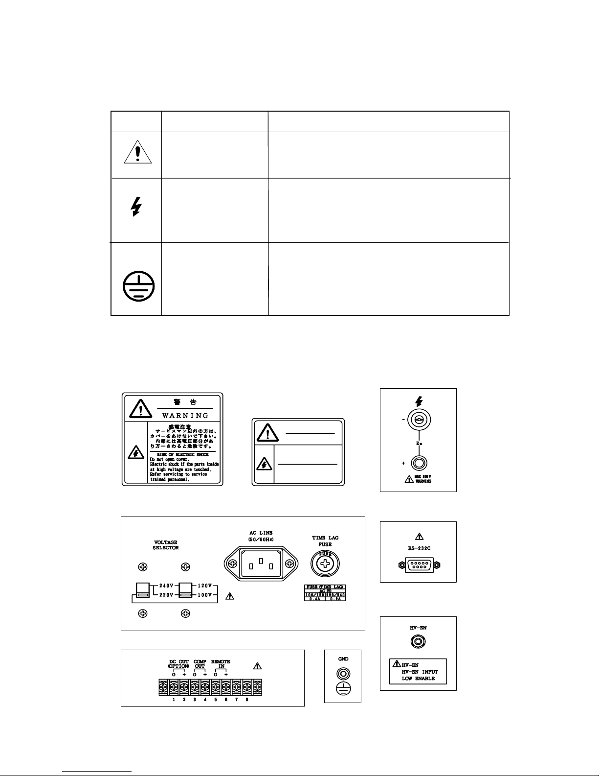
1.2 Symbols on the Super Megohmmeter
Safety Warning Labels on the Super Megohmmeter
Symbol Meaning Description
WARNING
This symbol is sh own at pats whose usage nee ds
referenc e to t he op erati on ma nual.
DANGER –
HIGH VOLTAGE
HAZARD
This symbol is shown at the Rx
“‑“/”+”
Measuring terminals which carry a high voltage
to be applied across the circuit to be measured.
This symbol is shown at the GND
terminal on the rear of the unit. If the
ground prong of the power cord plug
cannot be grounded, this terminal must be
connected to the ground.
1) DANGER and WARNING Labels on the Housing and Front Panel
2) DANGER and WARNING Labels on the Rear Panel
www.GlobalTestSupply.com
Find Quality Products Online at: sales@GlobalTestSupply.com
iv
2. Operating Environmental Precautions
D
DANGER
■Do not operate the super megohmmeters in the presence of flammable gas. There is s
possibility of an explosion and/or fire.
■D
o not touch the Rx “–”/“+” measuring terminals on the front panel of the instrument
during measurement. They output a maximum of 1000 V (
SM-8220/8215) or 100 V
(SM-8213) for measurement .
WARN ING
■Ground the ground prong of the power cord plug to avoid electrical shock. If the ground
prong cannot be grounded, connect the GND t
erminal on the r ear of t he in stru men t t o a
ground. When the power cord plug is connected to the AC line socket via an
accessory 3-prong to 2-prong adapter, the g reen ground tab of the adapter to the
ground.
■D
o not remove the housing cover of the instrument. Even after turning off the instrumen
t
p
ower switch, a dangerous residual voltage may be present for several minutes after t he
power is tur ned off. If r epair or in ternal readjus tment is neede d, contact your
dealer or Hioki representative
.
CAUTION
■Before turning on the power switch for the instrument, check that the VOLTAGE
SELECTOR switches are set for your local AC line voltage. If the wrong AC line voltage is
applied t
o the unit, it will be damaged (higher voltage supply) or will not function
properly (lower voltage supply).
See 1.3 Setting VOLTAGE SELECTOR Switches for setting.
Use the right size and amperage power fuse. If a fuse of incorrect amperage is inserted
into the fuse holder, the unit will be damaged.
See 1.4 Checking the Fuse Amperage for a correct fuse amperage.
■Do not insta ll or operate the supe r meg hommeter on a su rface w hich is not level or
not stable.
www.GlobalTestSupply.com
Find Quality Products Online at: sales@GlobalTestSupply.com
v
3. Installation Precaution
4. Instrument Handling Precautions
CAUTION
Do not install or place the supe r me g oh mme te r i n a lo ca ti on which is not level, not
stable or not sturdy enough to hold the instrument and other related items.
WARNING
■If the instrument generates smoke or smell, unplug the power cord.
If such an instrument is kept powered on, it may cause a fire.
Contact your dealer or Hioki representative for repair.
■Do not operat e th e inst rumen t wi th a wet han d. Thi s may caus e elect ric al sho ck.
CAUTION
■When moving or transporting the super megohmmeter, avoid shock and vibration as much
as possible. For long-distance transportation,
put the instrume nt in a shock-absorbing
carton or use the original shipping carton.
■ Wh
en not using the super megohmmeter for an extended period of time, unplug the power
co
rd from the AC line socket. Put a dust cover on the instrument. Store it in a place free of
corrosive gas and vi
bration, with a surrounding temperature within the range from –5 to
45℃,
and humidity less than 85% RH.
■ Do not pl ace an ythi ng on t he inst rum ent.
www.GlobalTestSupply.com
Find Quality Products Online at: sales@GlobalTestSupply.com

vi
BRIEF DESCRIPTION
About the SM-8200 Series Super Megohmmeters
The SM-8200 Series super megohmmeters are insulation resistance meters consisting of a constant voltage
power supply and a high sensitive current measuring section. The super megohmmeters are designed to
measur e the el ect rical resi stanc e of in sul ating mate rial s with high insul ation pro perti es.
The resistance measuring ranges of the SM-8200 Seri es are as follows:
SM-8213: 2.5×10⁴ to 2×10¹²Ω
SM-8215: 2.5×10⁵ to 2×10¹³Ω
SM-8220: 5.0×10⁴ to 2×10¹⁶Ω
Each model of the super megohmmeters is provided with an LCD 320×240 dot display for easy
observation of necessary information, including measuring voltage, measured resistance in both
digital and analog, timer, and resultant GO/NO judgment.
The following shows the main specifications for the super megohmmeters.
For detailed specifications, see 2. SPECIFICATIONS.
For optional accessories, see 9. OPTIONAL ACCESSORIES.
Main Specific ations –
For detailed speci fications, see 2. SPEC IFICATIONS.
For optional accessories, see 9. OPTIONAL ACCESSORIES.
Measuring Voltage Ranges:
SM-8213 – 5, 10, 15, 25, 50 and 100 V
SM-8215 – 50, 100, 250, 500 and 1000 V
SM-8220 – 10, 25, 50, 100, 250, 500 and 1000 V
Measuring Resistance Range:
SM-8213: 2.5×10⁴ to 2×10¹²Ω
SM-8215: 2.5×10⁵ to 2×10¹³Ω
SM-8220: 5.0×10⁴ to 2×10¹⁶Ω
Timer Function: Provided
Comparison and Judgment Function: Pro vided
HV-EN (High Voltage Enable) Interlocking Function: Provided
Voltage Charging Function: Provided
Voltage Discharging Function: Provided
RS-232C Interface Conn ector: Provided
Remote Measurement Function: Provided
DC Signal Output Function: Optional
1/R output or proportional to resistance value output
www.GlobalTestSupply.com
Find Quality Products Online at: sales@GlobalTestSupply.com

vii
Organization of This Operation Manual
This operation manual contains the following 10 sections.
1. PREPARATION BEFORE
OPERATION
This section describes precautions for unpacking and AC line voltage setting.
2. SPECIFICATIONS
This section describes the specifications for the SM-8200 Series super megohmmeters and
optional accessories.
3. OPERATING PRINCIPLE
This section describes the operating principle with a block diagram of the SM-8200 S eries.
4. FAMILIARIZATION WITH CONTROLS AND PARTS
This section describes the functions of the controls and parts on the front and rear panels.
5. PREPARATION FOR MEASUREMENT
This section describes the LCD display in detail for the measuring mode, setting mode and
operations. A variety of measured value display methods are also given.
6. MEASUREMENT
This section provides details for function setting, connection to the work to be measured, and
usage of a vari ety of optio nal m easur ing j igs a nd elec tro des.
7. RS-232C INTERFACE
This section describes the application of the serial port interface.
8. REMOTELY CONTROLLED MEASUREMENT
This section describes the remote measuring function.
9. INTRODUCTION OF OPTION ALS
This section describes the optional accessories, including guard chips, DC signal outputs, and
others.
10. MAINTENANCE AND MISCELANEOUS
This section describes maintenance and calibration.
11.
EXTERNAL APPEARANCE
This section inclu des front , rea r and side v iew illust rat ions of th e inst rumen t wit h di mens ions .
www.GlobalTestSupply.com
Find Quality Products Online at: sales@GlobalTestSupply.com

a
CONTENTS
1. PRE PA RAT ION BE FO RE O PER AT ION . . . . . . . . . . . . . . . . . . . . . . . 1
1. 1 Unpacking and Checking of the Contents . . . . . . . . . . . . . . . . . . . 1
1. 2 Operating AC Line Volta ge . . . . . . . . . . . . . . . . . . . . . . . . . . . . . . 2
1. 3 Setting the VOLTAGE SELECTOR Switches . . . . . . . . . . . . . . . . . . 2
1. 4 Checking the Fuse Amperage. . . . . . . . . . . . . . . . . . . . . . . . . . . . . 3
1. 5 G rounding the Chas sis . . . . . . . . . . . . . . . . . . . . . . . . . . . . . . . . . . 4
1. 6 Warm-u p Period . . . . . . . . . . . . . . . . . . . . . . . . . . . . . . . . . . . . . . . 5
2. SPECIFICATIONS . . . . . . . . . . . . . . . . . . . . . . . . . . . . . . . . . . . 6
2.1 Measuring Performance . . . . . . . . . . . . . . . . . . . . . . . . . . . . . 6
2.2 Function Specifications . . . . . . . . . . . . . . . . . . . . . . . . . . . . 7
2.3 Other Electrical and Physical Data . . . . . . . . . . . . . . . . . . . . 7
2.4 Optional Functions and Accessories . . . . . . . . . . . . . . . . . . . 8
3. OPERATING PRINCIPLE . . . . . . . . . . . . . . . . . . . . . . . . . . . . . . . 10
4. FAM ILI AR IZA TIO N WI TH CON TR OLS AND PA RTS . . . . . . . . . . . . . 11
4.1 Front Panel . . . . . . . . . . . . . . . . . . . . . . . . . . . . . . . . . . . . 11
4.2 Rear Panel . . . . . . . . . . . . . . . . . . . . . . . . . . . . . . . . . . . . . 13
4.3 Measuring Display . . . . . . . . . . . . . . . . . . . . . . . . . . . . . . . 15
4.4 Measuring Condition Setting Display . . . . . . . . . . . . . . . . . . 16
4.5 Meanings of the Status and Mode Notices. . . . . . . . . . . . . . . . 17
5. PREPARATION FOR A MEASUREMENT . . . . . . . . . . . . . . . . . . . . . 18
5.1 Preparation. . . . . . . . . . . . . . . . . . . . . . . . . . . . . . . . . . . . . 18
5.2 Calibration . . . . . . . . . . . .. . . . . . . . . . . . . . . . . . . . . . . . 19
5.3 Basic Procedures for a Measurement. . . . . . . . . . . . . . . . . . . 20
6. MEASUREMENT. . . . . . . . . . . . . . . . . . . . . . . . . . . . . . . . . . . . 21
6.1 Measuring Method. . . . . . . . . . . . . . . . . . . . . . . . . . . . . . . . 21
6.2 Discharging Function . . . . . . . . . . . . . . . . . . . . . . . . . . . . . 22
6.3 Charging Function . . . . . . . . . . . . . . . . . . . . . . . . . . . . . . 22
6. 4 Int erl oc kin g F unc tio n – Usi ng the HV -EN Con ne cto r . . . . . . . . 23
6
.5 Comparison and Judgment Function . . . . . . . . . . . . . . . . . . . 24
6.6 Setting a Variety of Functions . . . . . . . . . . . . . . . . . . . . . . . 25
6.6.1 Setting the Timer . . . . . . . . . . . . . . . . . . . . . . . . . . . . . . . 25
6.6.2 Setting the Comparison GO/NO Judgment Level . . . . . . . . . 25
www.GlobalTestSupply.com
Find Quality Products Online at: sales@GlobalTestSupply.com

b
6.6.3 Settin g Buzzer Sound ON/OFF . . . . . . . . . . . . . . . . . . . . . . 26
6.6.4 S etting the Charging Time, Measu ring Time, Comparison
GO/NO Judging Level and Buzzer Sound ON/OFF. . . . . . . . . 26
6.7 Changes in the Current Flowing th rough Insulators. . . . . . . . . 28
7. RS-232C INTERFACE . . . . . . . . . . . . . . . . . . . . . . . . . . . . . . . . 30
7.1 RS-232C Communication Commands . . . . . . . . . . . . . . . . . . . 30
7.2 Applications of Commands . . . . . . . . . . . . . . . . . . . . . . . . . . 31
7.3 Connector Specifications. . . . . . . . . . . . . . . . . . . . . . . . . . . 31
7.4 Printer Output . . . . . . . . . . . . . . . . . . . . . . . . . . . . . . . . . . 32
8. REMOTELY CONTROLLED MEASUREMENT . . . . . . . . . . . . . . . . . 33
9. INTRODUCTION OF OPTI ONS . . . . . . . . . . . . . . . . . . . . . . . . . . . 36
9.1 Guard Tip . . . . . . . . . . . . . . . . . . . . . . . . . . . . . . . . . . . . . 36
9.2 DC Signal Outputs. . . . . . . . . . . . . . . . . . . . . . . . . . . . . . . . 38
9.2.1 DC Output, RP-8000
– Directly proportional or linear to resistance . . . . . . . . . . 38
9.2.2 DC Output, RI-8000
– Inversely proportional or 1/R to resistance . . . . . . . . . . 40
10. MAINTENANCE AND MISCELANEOUS . . . . . . . . . . . . . . . . . . . . 41
10.1 Periodical Checking . . . . . . . . . . . . . . . . . . . . . . . . . . . . . 41
10.2 Storage, Transportation and Abando n . . . . . . . . . . . . . . . . . 41
11. EXTERNAL APPEARANCE . . . . . . . . . . . . . . . . . . . . . . . . . . . . . 42
www.GlobalTestSupply.com
Find Quality Products Online at: sales@GlobalTestSupply.com
1
1. PREPARATION BEFORE OPERATION
1.1 Unpacking and Ch ecking of the Conte nts
When you have received the carton of the SM-8200 Series super megohmmeter, carefull y unpack
it, and take out every thing from the carton.
Although the instrument and its accessories are severely inspected before shipment from factory,
visuall y ch eck th e it ems a nd th eir q uanti ties .
Keep the ship ping cart on fo r reus e at a later sta ge.
1) Visually check the external view of the instrument and its accessories.
2) Check the qua ntiti es of the li st in a ccor danc e with the fo llowi ng li st:
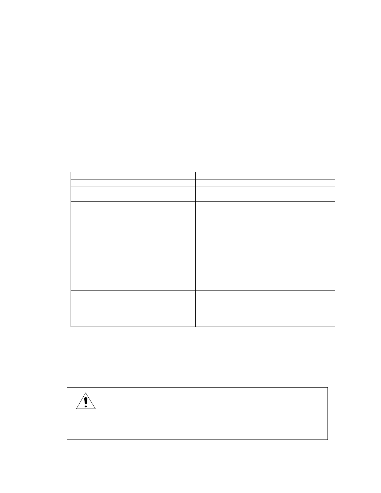
Table 1.1 List of Standard Accessories
Item Reference No. Q’ty Remarks
Operation manual 0PA00007 1 This item means this booklet.
Power cord 0AC00001 1 Power cord with 3-prong plug with third
for grounding
Power cord plug
adapter
0AA00002 1 This adapter makes it possible to use
the 3-prong plug power cord with
2-prong AC output.
Attached to the power cord 3-
prong plug when shipping
from factory
Measuring rod
(Red)
0GE00002 1 A measuring rod with a 1-
meter cord to be connected to the Rx ‘‑’
socket.
Measuring rod
(Black)
0GE00001 1 A measuring rod with a 1-
meter cord to be connected to the Rx ‘+’
socket.
Shorting plug 0GZ00003 1 A plug to be plugged to the
HV-EN so cket of the r ear of
the instr umen t. It i s plug ged
to the HV-EN socket when
shipping from factory.
Important!
When the accessory shorting plug is not plugged to the HV-EN socket on the rear of the
instrument, the measuring high voltage is not output.
Note: The shorting plug is plugged to the HV-EN socket when shipping from factory.
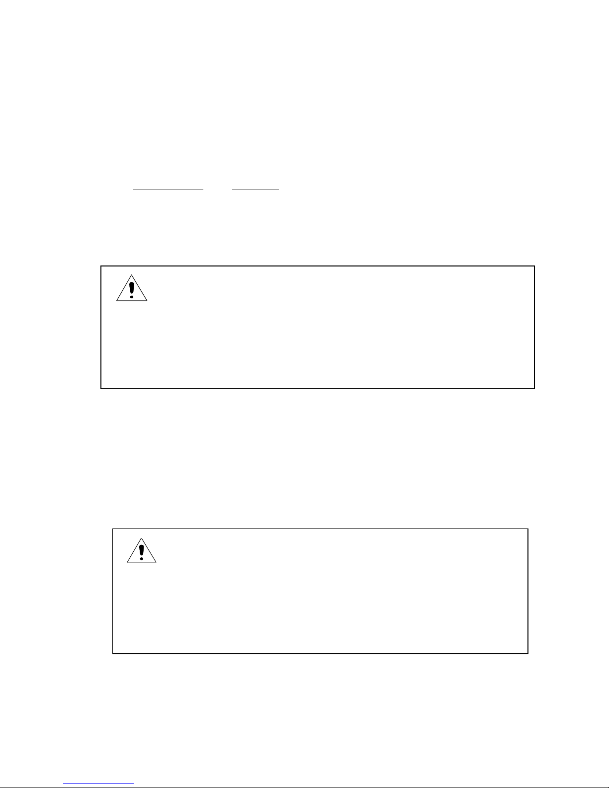
CAUTION
When plugging the shorting plug, make sure that the power is turned off, otherwise,
there is an el ectr ic sh ock h azar d.
www.GlobalTestSupply.com
Find Quality Products Online at: sales@GlobalTestSupply.com
2
Upon checking the instrument and accessories, if any damage is found, immediate ly contact
your dealer or Hioki representative.
1.2 Operating AC Line Voltage
The super meg o h memeter c a n b e o p er a ted from on e o f th e following AC power s o u r c e w hen the
VOLTAGE SELECTOR switches are set accordingly.
AC Line Voltage
Frequency
100 V ±10% 50/60 Hz
120 V ±10% 50/60 Hz
220 V ±10% 50/60 Hz
240 V +10V,‑10% 50/60 Hz
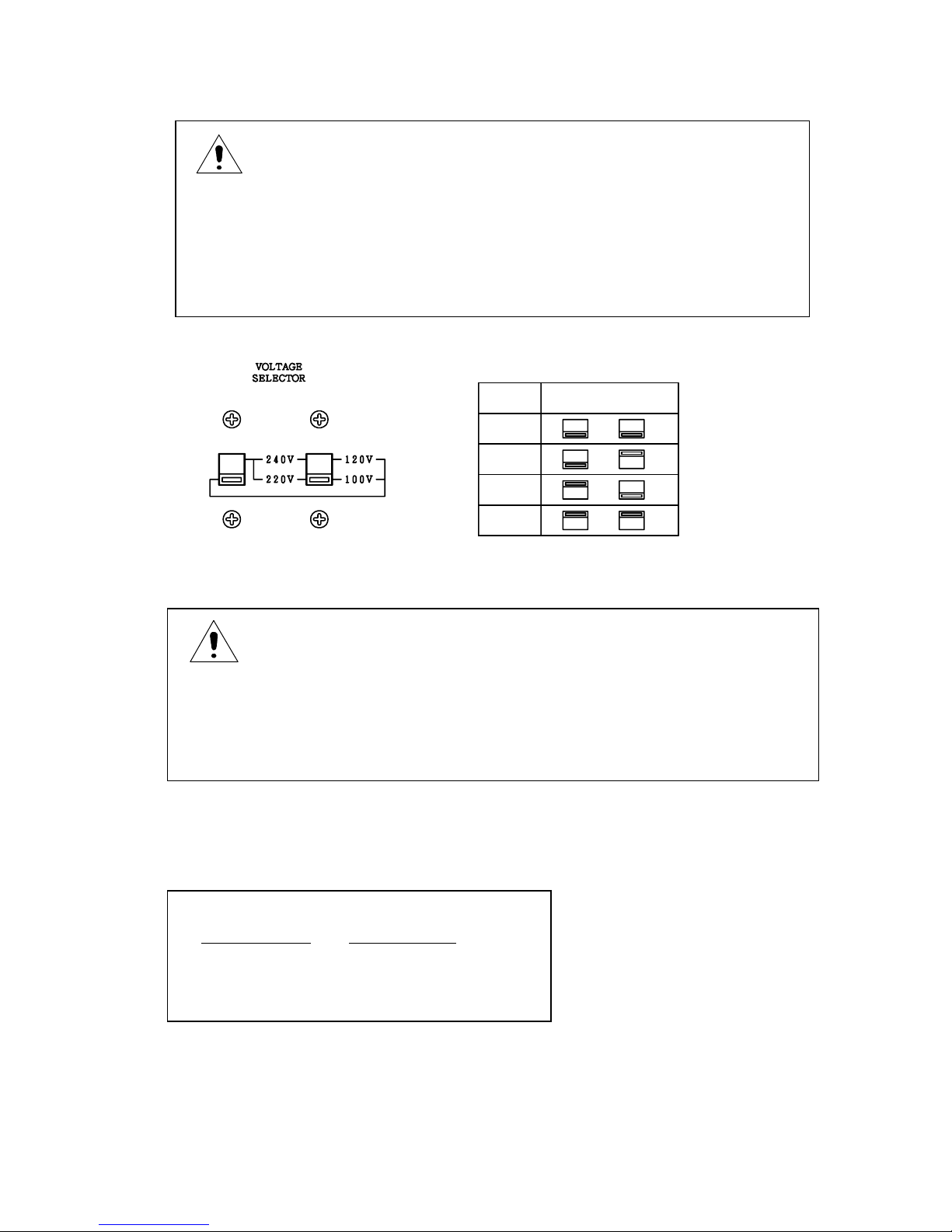
1.3 Setting VOLTAGE SELECTOR Switches
The super megohmmeter can be operated fro m one of the AC lin e voltages of 100 V, 120 V, 220 V
and 240 V by setting the VOLTAGE SE LECTOR switch es to the specific position s, respectively.
Confirm the switch setting to the specific positions in accordance with Fig. 1.1.
If they are not set properly, correct their positions, accordingly.
To change the position of the switch, insert the tip of a flat blade screwdriver into the slot of the
switch lever, and slide the lever upward or downward.
CAUTION
Before connecting the power cord to the AC outlet socket, confirm tha
t the VOLTAGE
SELECTOR switches on the rear panel are set to the positions, accordingly (See 1.3
Setting the VOLTAGE SELECTOR Switches.).
If the switches are set to wrong positions, a fire or burn may occur.
CAUTION
To chan ge th e VOLT ASGE SELE CTOR swit ch po sitio ns, b e sur e to
Unplu g the po wer co rd p lug fr om th e AC li ne soc ket to prev ent a
possible damage.
When th e swi tch po siti on is chan ged wh ile t he vo ltag e is on , the
Switch contacts will be damaged.
www.GlobalTestSupply.com
Find Quality Products Online at: sales@GlobalTestSupply.com
3
V
O
L
T
A
G
E
S
E
L
E
C
T
O
R
100V
120V
220V
240V
Fig. 1.1 VOLTAGE SELECTOR Switch Setting
1.4 Checking the Fuse Amperage
The fuse holder of the instrument contains a time lag fuse of the following amperage:
CAUTION
The VOLTAGE SELECTOR switches have two positions –
up and down. Slide the
switch lever to either position until it stops.
Do not leave the lever at a neutral position. If the lever is set at a neutral position, a
normal function cannot be obtained, and it will cause a failure.
CAUTION
When the VOLTAGE SELECTOR switch position is changed, fuse amperage must be
changed t o me et the r equ irem ents of the n ew AC line v olt age.
Incorr ect fu se am perag e wil l cau se a f ailur e of th e inst rum ent.
Time Lag Fuse
AC Line Voltage
Fuse Amperage
100 V/120 V 0.4 A
220 V/240 V 0.2 A
www.GlobalTestSupply.com
Find Quality Products Online at: sales@GlobalTestSupply.com
4
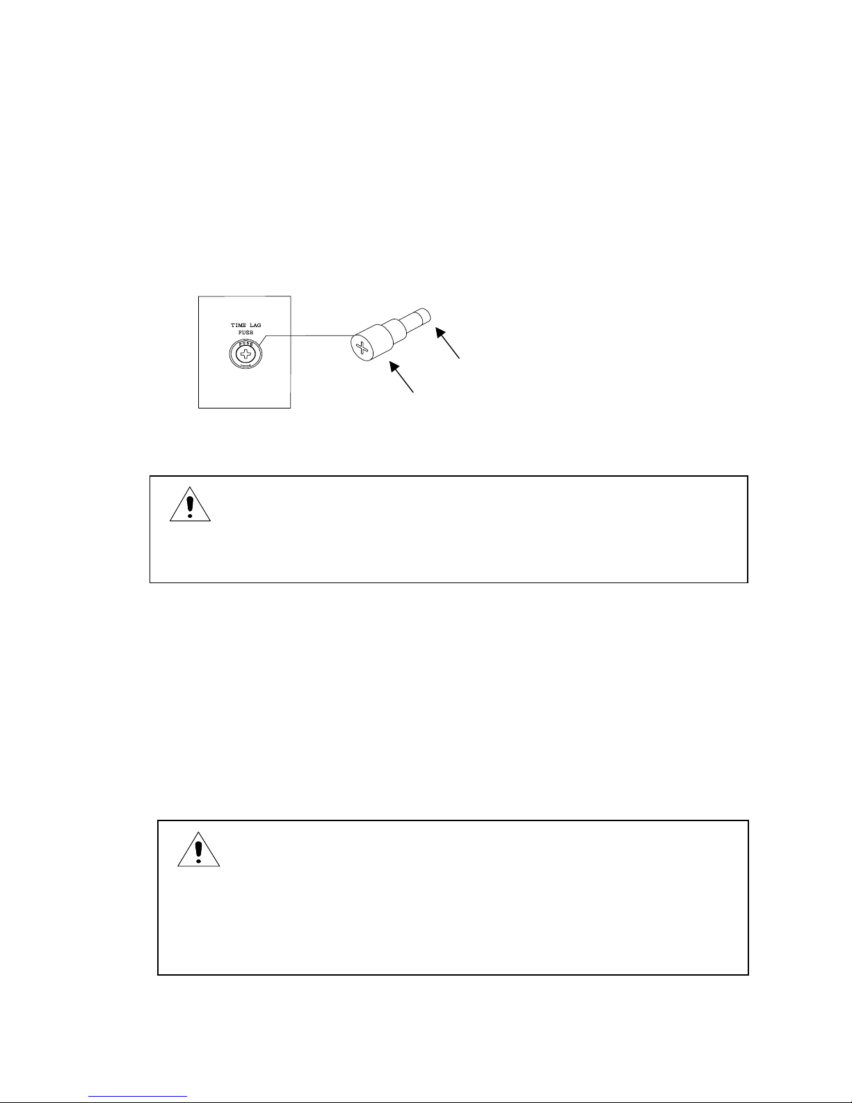
Fuse Replacement
The fuse is inserted in the FUSE holder (Fig. 1.2) on the rear of the unit.
Remove the cap, and replace the fuse with a new one with a correct amperage.
To remove the cap of the fuse holder, use a 4 mm Phillips screwdriver, and turn the cap
counterclockwise.
To set the cap in position, insert the cap, holding the fuse in to the holder , and turn it wi th the
screwdriver.
Fig. 1.2 Fuse Holder and Fuse Replacement
1.5 Grounding the Chassis
To avoid an electr ical shock accide nt, connect the GND terminal on the rear of the u nit to the
ground prong of the power cord to the ground post of the AC line system.
The round prong of the 3-pron g plug of the power cord is th e ground prong.
It is recommended to use an AC line socket with its third contact grounded for connection of the
accessory 3-prong power cord.
To use the accessory 3-prong to 2-prong a dapter to connect the power cord to a 2-co ntact AC line
socket, make sure to ground the green tab of the adapter.
WARNING
To replace or check the fuse, make sure to disconnect the power cord from the AC line
socket. If not, ther e is a fe ar of el ect rical shoc k.
WARNING
To prevent an accident, connect the ground prong of the power cord
Plug to the ground post of the AC line system. If it is impossible to
ground the ground prong of the power cord plug, be sure to connect
the GND terminal on the rear of the unit.
Fuse
Ca
p
www.GlobalTestSupply.com
Find Quality Products Online at: sales@GlobalTestSupply.com

5
1.6 Warm-up Period
To obtain the performance of published specifications, allow the SM-8200 Series super
megohmmeter to warm for a minimum of 30 minutes.
www.GlobalTestSupply.com
Find Quality Products Online at: sales@GlobalTestSupply.com
6
2. SPECIFICATIONS
2.1 Measuring Performance
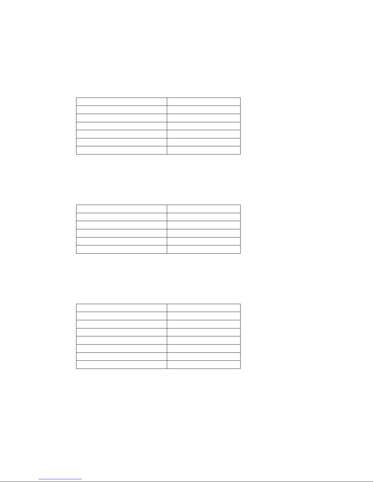
1) Electrical Resistance Measurement
SM-8213
Measuring Range (Ω)
Measuring Voltage
5.0 × 10⁵ to 2 × 10¹²
100 V
2.5 × 10⁵ to 1 × 10¹²
50 V
1.25 × 10⁵ to 5 × 10¹¹
25 V
7.5 × 10⁴ to 3 × 10¹¹
15 V
5.0 × 10⁴ to 2 × 10¹¹
10 V
2.5 × 10⁴ to 1 × 10¹¹
5 V
Accuracy of measuring voltage: ±3% of set value
Measuring output current: 50 mA maximum
Accuracy of measurement: ±10% (A range of 10 times of the minimum
value of each range)
SM-8215
Measuring Range (Ω)
Measuring Voltage
5.0 × 10⁶ to 2 × 10¹³
1000 V
2.5 × 10⁶ to 1 × 10¹³
500 V
1.25 × 10⁶ to 5 × 10¹²
250 V
5.0 × 10⁵ to 2 × 10¹²
100 V
2.5 × 10⁵ to 1 × 10¹²
50 V
Accuracy of measuring voltage: ±3% of set value
Measuring output current: 2 mA maximum
Accuracy of measurement: ±10% (A range of 10 times of the minimum
value of each range)
SM-8220
Measuring Range (Ω)
Measuring Voltage
5.0 × 10⁶ to 2 × 10¹⁶
1000 V
2.5 × 10⁶ to 1 × 10¹⁶
500 V
1.25 × 10⁶ to 5 × 10¹⁵
250 V
5.0 × 10⁵ to 2 × 10¹⁵
100 V
2.5 × 10⁵ to 1 × 10¹⁵
50 V
1.25 × 10⁵ to 5 × 10¹⁴
25 V
5.0 × 10⁴ to 2 × 10¹⁴
10 V
Accuracy of measuring voltage: ±3% of set value
Measuring output current: 2 mA maximum
Accuracy of measurement: ±10% (A range of 10 times of the minimum
value of each range) except for×10
8
range.
±20% for×10
8
range
2) Measuring Time (Sampling Cycle)
Approx. 200 ms
www.GlobalTestSupply.com
Find Quality Products Online at: sales@GlobalTestSupply.com
 Loading...