

Page 1

SUPER MEGOHMMETER
INSTRUCTION MANUAL
SM-8213
SM-8215
SM-8220
www.GlobalTestSupply.com
Find Quality Products Online at: sales@GlobalTestSupply.com
Page 2

i
The super megohmmeter is a unique resistance meter designed to measure highresistance in a wide range.
The meter outputs a high test voltage – 1000 V maximum for the SM-8220/8215, and 100 V
maximum for the SM-8213 – to apply across the sample circuit.
Operators are requested to read this operation manual thoroughly before trying to operate the
instrument for safety and to prevent electrical shock and damage to the measured circuit.
Keep this manual where all staff can access it any time.
www.GlobalTestSupply.com
Find Quality Products Online at: sales@GlobalTestSupply.com
Page 3
ii
DANGER
A “DANGER” CALLS ATTENTION TO A CONDITION OR POSSIBLE
SITUATION THAT CAN CAUSE DEATH OR INJURY TO THE
OPERATOR OR NEAR PESONS.
1. Safety Precautions
Operators of the SM-8200 Series super megohmmeter are requested to read this operation
manual thoroughly before operation for safety and to obtain best performance.
Operators are also requested to strictly observe all the DANGER, WARNING, and CAUTION
notices in this manual and on the instrument to prevent injury and damage.
1-1 Safety Warnings
This operation manual includes some DANGER!, WARNING!, and CAUTION! notice with a
symbol. These must be observed for safety of the operator and other persons, as well as for
protection of your super megohmmeter and samples from possible damage and destruction.
WARNIN G
A “WARNING” CALLS ATTENTION TO A CONDITION OR POSSIBLE
SITUATION TH AT COULD CAUSE DE ATH OR INJURY TO THE
OPERATOR OR NEAR PESONS.
CAUTION
A “CAUTION” calls attention to a condition or possible situation that
could cause injury to the operator or persons nearby and damage and
destroy the super megohmmeter and samples.
www.GlobalTestSupply.com
Find Quality Products Online at: sales@GlobalTestSupply.com
Page 4
iii
背面パネル
警告、危険シール
DANGER
端子より高電圧発生の為、
感電の恐れあり。
HIGH VOLTAGE
危険
高電圧危険
Electric shock hazard!
Terminals carry high voltage.
正面パネル
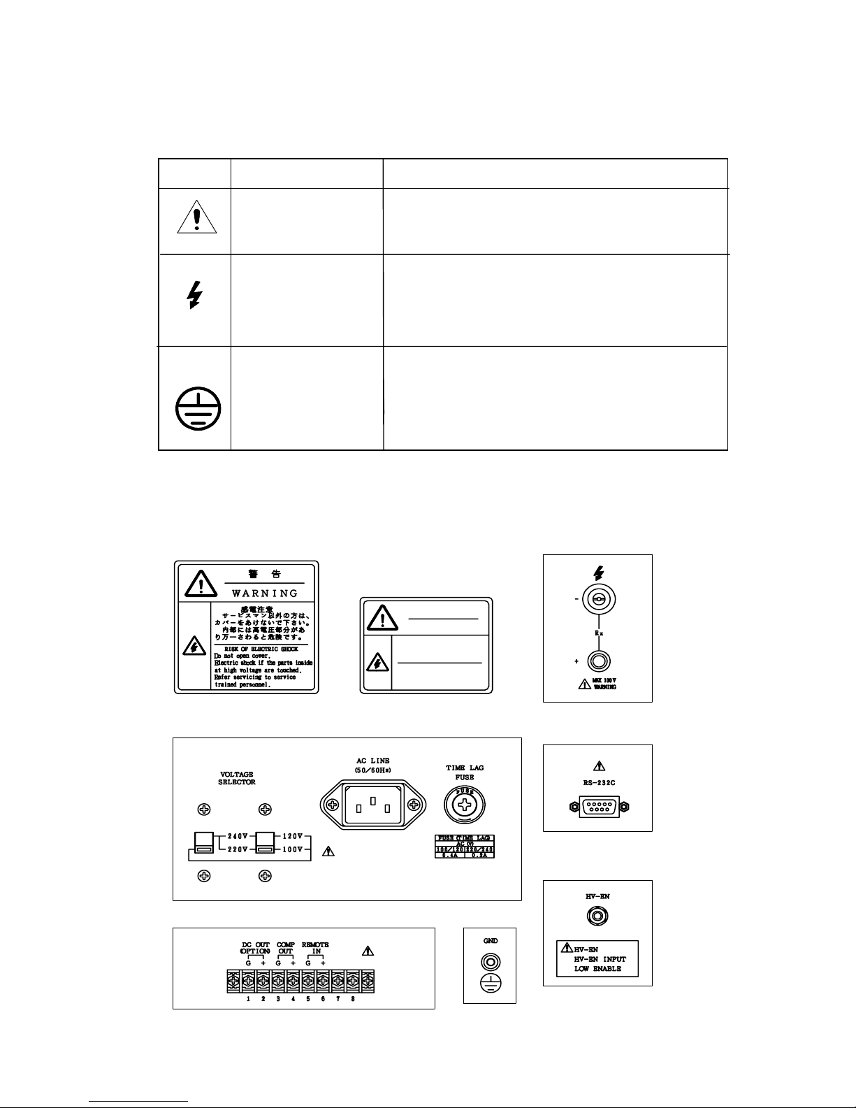
1.2 Symbols on the Super Megohmmeter
Safety Warning Labels on the Super Megohmmeter
Symbol Meaning Description
WARNING
This symbol is sh own at pats whose usage nee ds
referenc e to t he op erati on ma nual.
DANGER –
HIGH VOLTAGE
HAZARD
This symbol is shown at the Rx
“‑“/”+”
Measuring terminals which carry a high voltage
to be applied across the circuit to be measured.
This symbol is shown at the GND
terminal on the rear of the unit. If the
ground prong of the power cord plug
cannot be grounded, this terminal must be
connected to the ground.
1) DANGER and WARNING Labels on the Housing and Front Panel
2) DANGER and WARNING Labels on the Rear Panel
www.GlobalTestSupply.com
Find Quality Products Online at: sales@GlobalTestSupply.com
Page 5
iv
2. Operating Environmental Precautions
D
DANGER
■Do not operate the super megohmmeters in the presence of flammable gas. There is s
possibility of an explosion and/or fire.
■D
o not touch the Rx “–”/“+” measuring terminals on the front panel of the instrument
during measurement. They output a maximum of 1000 V (
SM-8220/8215) or 100 V
(SM-8213) for measurement .
WARN ING
■Ground the ground prong of the power cord plug to avoid electrical shock. If the ground
prong cannot be grounded, connect the GND t
erminal on the r ear of t he in stru men t t o a
ground. When the power cord plug is connected to the AC line socket via an
accessory 3-prong to 2-prong adapter, the g reen ground tab of the adapter to the
ground.
■D
o not remove the housing cover of the instrument. Even after turning off the instrumen
t
p
ower switch, a dangerous residual voltage may be present for several minutes after t he
power is tur ned off. If r epair or in ternal readjus tment is neede d, contact your
dealer or Hioki representative
.
CAUTION
■Before turning on the power switch for the instrument, check that the VOLTAGE
SELECTOR switches are set for your local AC line voltage. If the wrong AC line voltage is
applied t
o the unit, it will be damaged (higher voltage supply) or will not function
properly (lower voltage supply).
See 1.3 Setting VOLTAGE SELECTOR Switches for setting.
Use the right size and amperage power fuse. If a fuse of incorrect amperage is inserted
into the fuse holder, the unit will be damaged.
See 1.4 Checking the Fuse Amperage for a correct fuse amperage.
■Do not insta ll or operate the supe r meg hommeter on a su rface w hich is not level or
not stable.
www.GlobalTestSupply.com
Find Quality Products Online at: sales@GlobalTestSupply.com
Page 6
v
3. Installation Precaution
4. Instrument Handling Precautions
CAUTION
Do not install or place the supe r me g oh mme te r i n a lo ca ti on which is not level, not
stable or not sturdy enough to hold the instrument and other related items.
WARNING
■If the instrument generates smoke or smell, unplug the power cord.
If such an instrument is kept powered on, it may cause a fire.
Contact your dealer or Hioki representative for repair.
■Do not operat e th e inst rumen t wi th a wet han d. Thi s may caus e elect ric al sho ck.
CAUTION
■When moving or transporting the super megohmmeter, avoid shock and vibration as much
as possible. For long-distance transportation,
put the instrume nt in a shock-absorbing
carton or use the original shipping carton.
■ Wh
en not using the super megohmmeter for an extended period of time, unplug the power
co
rd from the AC line socket. Put a dust cover on the instrument. Store it in a place free of
corrosive gas and vi
bration, with a surrounding temperature within the range from –5 to
45℃,
and humidity less than 85% RH.
■ Do not pl ace an ythi ng on t he inst rum ent.
www.GlobalTestSupply.com
Find Quality Products Online at: sales@GlobalTestSupply.com
Page 7

vi
BRIEF DESCRIPTION
About the SM-8200 Series Super Megohmmeters
The SM-8200 Series super megohmmeters are insulation resistance meters consisting of a constant voltage
power supply and a high sensitive current measuring section. The super megohmmeters are designed to
measur e the el ect rical resi stanc e of in sul ating mate rial s with high insul ation pro perti es.
The resistance measuring ranges of the SM-8200 Seri es are as follows:
SM-8213: 2.5×10⁴ to 2×10¹²Ω
SM-8215: 2.5×10⁵ to 2×10¹³Ω
SM-8220: 5.0×10⁴ to 2×10¹⁶Ω
Each model of the super megohmmeters is provided with an LCD 320×240 dot display for easy
observation of necessary information, including measuring voltage, measured resistance in both
digital and analog, timer, and resultant GO/NO judgment.
The following shows the main specifications for the super megohmmeters.
For detailed specifications, see 2. SPECIFICATIONS.
For optional accessories, see 9. OPTIONAL ACCESSORIES.
Main Specific ations –
For detailed speci fications, see 2. SPEC IFICATIONS.
For optional accessories, see 9. OPTIONAL ACCESSORIES.
Measuring Voltage Ranges:
SM-8213 – 5, 10, 15, 25, 50 and 100 V
SM-8215 – 50, 100, 250, 500 and 1000 V
SM-8220 – 10, 25, 50, 100, 250, 500 and 1000 V
Measuring Resistance Range:
SM-8213: 2.5×10⁴ to 2×10¹²Ω
SM-8215: 2.5×10⁵ to 2×10¹³Ω
SM-8220: 5.0×10⁴ to 2×10¹⁶Ω
Timer Function: Provided
Comparison and Judgment Function: Pro vided
HV-EN (High Voltage Enable) Interlocking Function: Provided
Voltage Charging Function: Provided
Voltage Discharging Function: Provided
RS-232C Interface Conn ector: Provided
Remote Measurement Function: Provided
DC Signal Output Function: Optional
1/R output or proportional to resistance value output
www.GlobalTestSupply.com
Find Quality Products Online at: sales@GlobalTestSupply.com
Page 8

vii
Organization of This Operation Manual
This operation manual contains the following 10 sections.
1. PREPARATION BEFORE
OPERATION
This section describes precautions for unpacking and AC line voltage setting.
2. SPECIFICATIONS
This section describes the specifications for the SM-8200 Series super megohmmeters and
optional accessories.
3. OPERATING PRINCIPLE
This section describes the operating principle with a block diagram of the SM-8200 S eries.
4. FAMILIARIZATION WITH CONTROLS AND PARTS
This section describes the functions of the controls and parts on the front and rear panels.
5. PREPARATION FOR MEASUREMENT
This section describes the LCD display in detail for the measuring mode, setting mode and
operations. A variety of measured value display methods are also given.
6. MEASUREMENT
This section provides details for function setting, connection to the work to be measured, and
usage of a vari ety of optio nal m easur ing j igs a nd elec tro des.
7. RS-232C INTERFACE
This section describes the application of the serial port interface.
8. REMOTELY CONTROLLED MEASUREMENT
This section describes the remote measuring function.
9. INTRODUCTION OF OPTION ALS
This section describes the optional accessories, including guard chips, DC signal outputs, and
others.
10. MAINTENANCE AND MISCELANEOUS
This section describes maintenance and calibration.
11.
EXTERNAL APPEARANCE
This section inclu des front , rea r and side v iew illust rat ions of th e inst rumen t wit h di mens ions .
www.GlobalTestSupply.com
Find Quality Products Online at: sales@GlobalTestSupply.com
Page 9

a
CONTENTS
1. PRE PA RAT ION BE FO RE O PER AT ION . . . . . . . . . . . . . . . . . . . . . . . 1
1. 1 Unpacking and Checking of the Contents . . . . . . . . . . . . . . . . . . . 1
1. 2 Operating AC Line Volta ge . . . . . . . . . . . . . . . . . . . . . . . . . . . . . . 2
1. 3 Setting the VOLTAGE SELECTOR Switches . . . . . . . . . . . . . . . . . . 2
1. 4 Checking the Fuse Amperage. . . . . . . . . . . . . . . . . . . . . . . . . . . . . 3
1. 5 G rounding the Chas sis . . . . . . . . . . . . . . . . . . . . . . . . . . . . . . . . . . 4
1. 6 Warm-u p Period . . . . . . . . . . . . . . . . . . . . . . . . . . . . . . . . . . . . . . . 5
2. SPECIFICATIONS . . . . . . . . . . . . . . . . . . . . . . . . . . . . . . . . . . . 6
2.1 Measuring Performance . . . . . . . . . . . . . . . . . . . . . . . . . . . . . 6
2.2 Function Specifications . . . . . . . . . . . . . . . . . . . . . . . . . . . . 7
2.3 Other Electrical and Physical Data . . . . . . . . . . . . . . . . . . . . 7
2.4 Optional Functions and Accessories . . . . . . . . . . . . . . . . . . . 8
3. OPERATING PRINCIPLE . . . . . . . . . . . . . . . . . . . . . . . . . . . . . . . 10
4. FAM ILI AR IZA TIO N WI TH CON TR OLS AND PA RTS . . . . . . . . . . . . . 11
4.1 Front Panel . . . . . . . . . . . . . . . . . . . . . . . . . . . . . . . . . . . . 11
4.2 Rear Panel . . . . . . . . . . . . . . . . . . . . . . . . . . . . . . . . . . . . . 13
4.3 Measuring Display . . . . . . . . . . . . . . . . . . . . . . . . . . . . . . . 15
4.4 Measuring Condition Setting Display . . . . . . . . . . . . . . . . . . 16
4.5 Meanings of the Status and Mode Notices. . . . . . . . . . . . . . . . 17
5. PREPARATION FOR A MEASUREMENT . . . . . . . . . . . . . . . . . . . . . 18
5.1 Preparation. . . . . . . . . . . . . . . . . . . . . . . . . . . . . . . . . . . . . 18
5.2 Calibration . . . . . . . . . . . .. . . . . . . . . . . . . . . . . . . . . . . . 19
5.3 Basic Procedures for a Measurement. . . . . . . . . . . . . . . . . . . 20
6. MEASUREMENT. . . . . . . . . . . . . . . . . . . . . . . . . . . . . . . . . . . . 21
6.1 Measuring Method. . . . . . . . . . . . . . . . . . . . . . . . . . . . . . . . 21
6.2 Discharging Function . . . . . . . . . . . . . . . . . . . . . . . . . . . . . 22
6.3 Charging Function . . . . . . . . . . . . . . . . . . . . . . . . . . . . . . 22
6. 4 Int erl oc kin g F unc tio n – Usi ng the HV -EN Con ne cto r . . . . . . . . 23
6
.5 Comparison and Judgment Function . . . . . . . . . . . . . . . . . . . 24
6.6 Setting a Variety of Functions . . . . . . . . . . . . . . . . . . . . . . . 25
6.6.1 Setting the Timer . . . . . . . . . . . . . . . . . . . . . . . . . . . . . . . 25
6.6.2 Setting the Comparison GO/NO Judgment Level . . . . . . . . . 25
www.GlobalTestSupply.com
Find Quality Products Online at: sales@GlobalTestSupply.com
Page 10

b
6.6.3 Settin g Buzzer Sound ON/OFF . . . . . . . . . . . . . . . . . . . . . . 26
6.6.4 S etting the Charging Time, Measu ring Time, Comparison
GO/NO Judging Level and Buzzer Sound ON/OFF. . . . . . . . . 26
6.7 Changes in the Current Flowing th rough Insulators. . . . . . . . . 28
7. RS-232C INTERFACE . . . . . . . . . . . . . . . . . . . . . . . . . . . . . . . . 30
7.1 RS-232C Communication Commands . . . . . . . . . . . . . . . . . . . 30
7.2 Applications of Commands . . . . . . . . . . . . . . . . . . . . . . . . . . 31
7.3 Connector Specifications. . . . . . . . . . . . . . . . . . . . . . . . . . . 31
7.4 Printer Output . . . . . . . . . . . . . . . . . . . . . . . . . . . . . . . . . . 32
8. REMOTELY CONTROLLED MEASUREMENT . . . . . . . . . . . . . . . . . 33
9. INTRODUCTION OF OPTI ONS . . . . . . . . . . . . . . . . . . . . . . . . . . . 36
9.1 Guard Tip . . . . . . . . . . . . . . . . . . . . . . . . . . . . . . . . . . . . . 36
9.2 DC Signal Outputs. . . . . . . . . . . . . . . . . . . . . . . . . . . . . . . . 38
9.2.1 DC Output, RP-8000
– Directly proportional or linear to resistance . . . . . . . . . . 38
9.2.2 DC Output, RI-8000
– Inversely proportional or 1/R to resistance . . . . . . . . . . 40
10. MAINTENANCE AND MISCELANEOUS . . . . . . . . . . . . . . . . . . . . 41
10.1 Periodical Checking . . . . . . . . . . . . . . . . . . . . . . . . . . . . . 41
10.2 Storage, Transportation and Abando n . . . . . . . . . . . . . . . . . 41
11. EXTERNAL APPEARANCE . . . . . . . . . . . . . . . . . . . . . . . . . . . . . 42
www.GlobalTestSupply.com
Find Quality Products Online at: sales@GlobalTestSupply.com
Page 11
1
1. PREPARATION BEFORE OPERATION
1.1 Unpacking and Ch ecking of the Conte nts
When you have received the carton of the SM-8200 Series super megohmmeter, carefull y unpack
it, and take out every thing from the carton.
Although the instrument and its accessories are severely inspected before shipment from factory,
visuall y ch eck th e it ems a nd th eir q uanti ties .
Keep the ship ping cart on fo r reus e at a later sta ge.
1) Visually check the external view of the instrument and its accessories.
2) Check the qua ntiti es of the li st in a ccor danc e with the fo llowi ng li st:
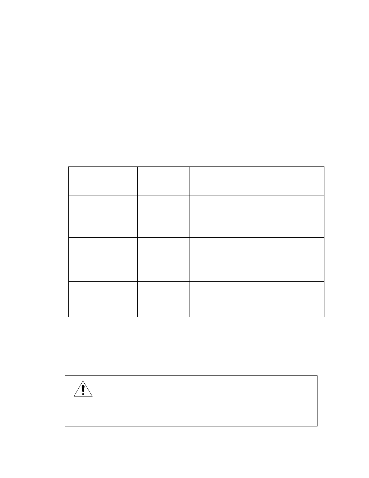
Table 1.1 List of Standard Accessories
Item Reference No. Q’ty Remarks
Operation manual 0PA00007 1 This item means this booklet.
Power cord 0AC00001 1 Power cord with 3-prong plug with third
for grounding
Power cord plug
adapter
0AA00002 1 This adapter makes it possible to use
the 3-prong plug power cord with
2-prong AC output.
Attached to the power cord 3-
prong plug when shipping
from factory
Measuring rod
(Red)
0GE00002 1 A measuring rod with a 1-
meter cord to be connected to the Rx ‘‑’
socket.
Measuring rod
(Black)
0GE00001 1 A measuring rod with a 1-
meter cord to be connected to the Rx ‘+’
socket.
Shorting plug 0GZ00003 1 A plug to be plugged to the
HV-EN so cket of the r ear of
the instr umen t. It i s plug ged
to the HV-EN socket when
shipping from factory.
Important!
When the accessory shorting plug is not plugged to the HV-EN socket on the rear of the
instrument, the measuring high voltage is not output.
Note: The shorting plug is plugged to the HV-EN socket when shipping from factory.
CAUTION
When plugging the shorting plug, make sure that the power is turned off, otherwise,
there is an el ectr ic sh ock h azar d.
www.GlobalTestSupply.com
Find Quality Products Online at: sales@GlobalTestSupply.com
Page 12
2
Upon checking the instrument and accessories, if any damage is found, immediate ly contact
your dealer or Hioki representative.
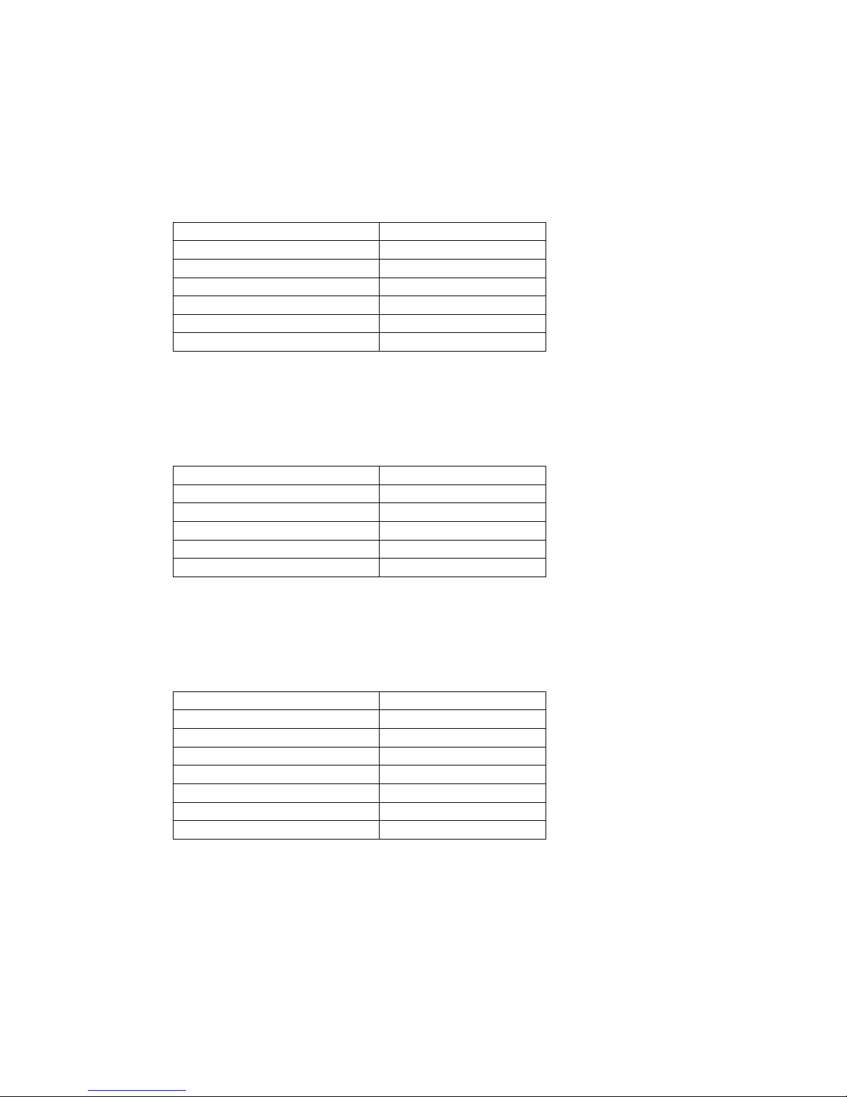
1.2 Operating AC Line Voltage
The super meg o h memeter c a n b e o p er a ted from on e o f th e following AC power s o u r c e w hen the
VOLTAGE SELECTOR switches are set accordingly.
AC Line Voltage
Frequency
100 V ±10% 50/60 Hz
120 V ±10% 50/60 Hz
220 V ±10% 50/60 Hz
240 V +10V,‑10% 50/60 Hz
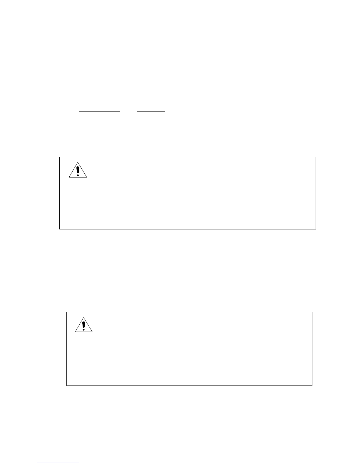
1.3 Setting VOLTAGE SELECTOR Switches
The super megohmmeter can be operated fro m one of the AC lin e voltages of 100 V, 120 V, 220 V
and 240 V by setting the VOLTAGE SE LECTOR switch es to the specific position s, respectively.
Confirm the switch setting to the specific positions in accordance with Fig. 1.1.
If they are not set properly, correct their positions, accordingly.
To change the position of the switch, insert the tip of a flat blade screwdriver into the slot of the
switch lever, and slide the lever upward or downward.
CAUTION
Before connecting the power cord to the AC outlet socket, confirm tha
t the VOLTAGE
SELECTOR switches on the rear panel are set to the positions, accordingly (See 1.3
Setting the VOLTAGE SELECTOR Switches.).
If the switches are set to wrong positions, a fire or burn may occur.
CAUTION
To chan ge th e VOLT ASGE SELE CTOR swit ch po sitio ns, b e sur e to
Unplu g the po wer co rd p lug fr om th e AC li ne soc ket to prev ent a
possible damage.
When th e swi tch po siti on is chan ged wh ile t he vo ltag e is on , the
Switch contacts will be damaged.
www.GlobalTestSupply.com
Find Quality Products Online at: sales@GlobalTestSupply.com
Page 13
3
V
O
L
T
A
G
E
S
E
L
E
C
T
O
R
100V
120V
220V
240V
Fig. 1.1 VOLTAGE SELECTOR Switch Setting
1.4 Checking the Fuse Amperage
The fuse holder of the instrument contains a time lag fuse of the following amperage:
CAUTION
The VOLTAGE SELECTOR switches have two positions –
up and down. Slide the
switch lever to either position until it stops.
Do not leave the lever at a neutral position. If the lever is set at a neutral position, a
normal function cannot be obtained, and it will cause a failure.
CAUTION
When the VOLTAGE SELECTOR switch position is changed, fuse amperage must be
changed t o me et the r equ irem ents of the n ew AC line v olt age.
Incorr ect fu se am perag e wil l cau se a f ailur e of th e inst rum ent.
Time Lag Fuse
AC Line Voltage
Fuse Amperage
100 V/120 V 0.4 A
220 V/240 V 0.2 A
www.GlobalTestSupply.com
Find Quality Products Online at: sales@GlobalTestSupply.com
Page 14
4
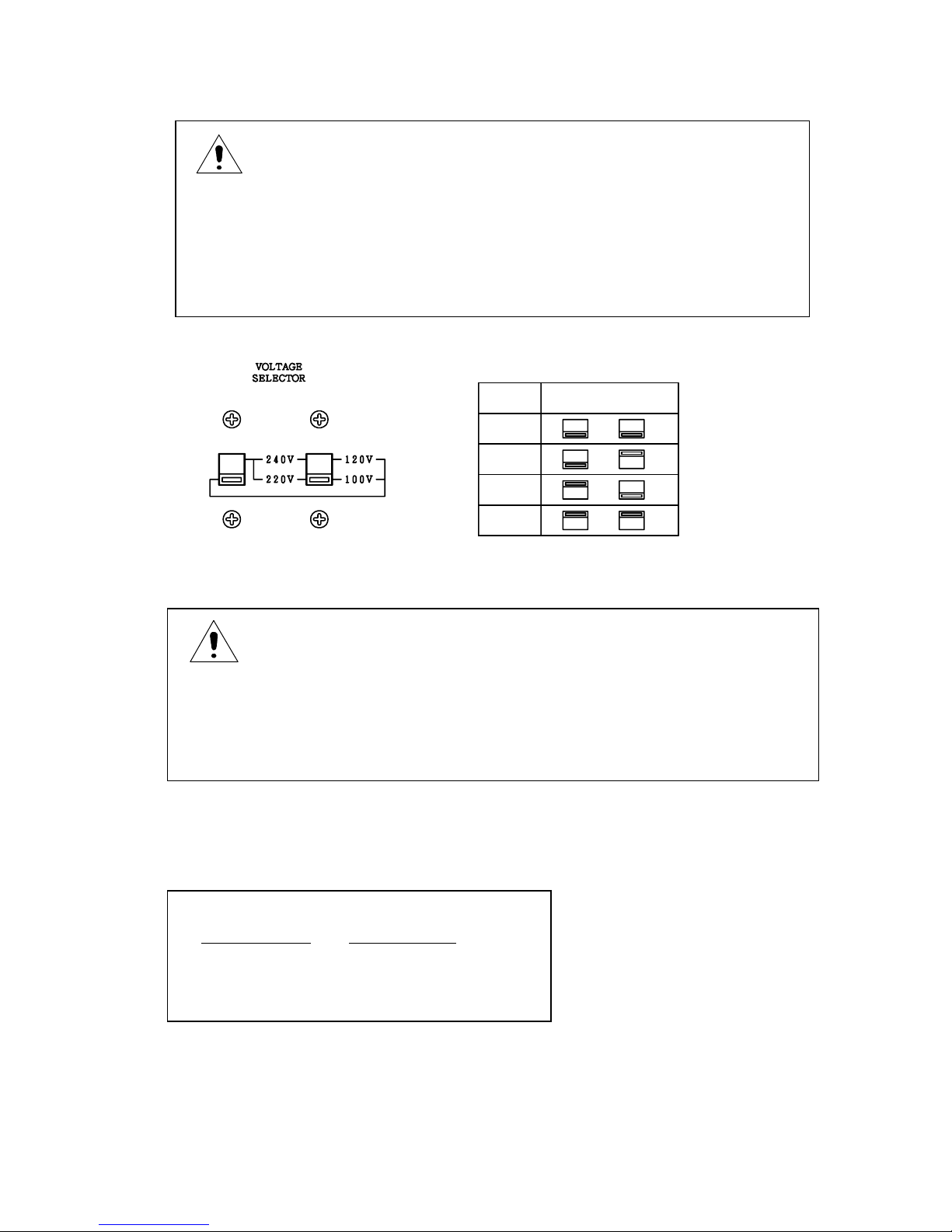
Fuse Replacement
The fuse is inserted in the FUSE holder (Fig. 1.2) on the rear of the unit.
Remove the cap, and replace the fuse with a new one with a correct amperage.
To remove the cap of the fuse holder, use a 4 mm Phillips screwdriver, and turn the cap
counterclockwise.
To set the cap in position, insert the cap, holding the fuse in to the holder , and turn it wi th the
screwdriver.
Fig. 1.2 Fuse Holder and Fuse Replacement
1.5 Grounding the Chassis
To avoid an electr ical shock accide nt, connect the GND terminal on the rear of the u nit to the
ground prong of the power cord to the ground post of the AC line system.
The round prong of the 3-pron g plug of the power cord is th e ground prong.
It is recommended to use an AC line socket with its third contact grounded for connection of the
accessory 3-prong power cord.
To use the accessory 3-prong to 2-prong a dapter to connect the power cord to a 2-co ntact AC line
socket, make sure to ground the green tab of the adapter.
WARNING
To replace or check the fuse, make sure to disconnect the power cord from the AC line
socket. If not, ther e is a fe ar of el ect rical shoc k.
WARNING
To prevent an accident, connect the ground prong of the power cord
Plug to the ground post of the AC line system. If it is impossible to
ground the ground prong of the power cord plug, be sure to connect
the GND terminal on the rear of the unit.
Fuse
Ca
p
www.GlobalTestSupply.com
Find Quality Products Online at: sales@GlobalTestSupply.com
Page 15

5
1.6 Warm-up Period
To obtain the performance of published specifications, allow the SM-8200 Series super
megohmmeter to warm for a minimum of 30 minutes.
www.GlobalTestSupply.com
Find Quality Products Online at: sales@GlobalTestSupply.com
Page 16
6
2. SPECIFICATIONS
2.1 Measuring Performance
1) Electrical Resistance Measurement
SM-8213
Measuring Range (Ω)
Measuring Voltage
5.0 × 10⁵ to 2 × 10¹²
100 V
2.5 × 10⁵ to 1 × 10¹²
50 V
1.25 × 10⁵ to 5 × 10¹¹
25 V
7.5 × 10⁴ to 3 × 10¹¹
15 V
5.0 × 10⁴ to 2 × 10¹¹
10 V
2.5 × 10⁴ to 1 × 10¹¹
5 V
Accuracy of measuring voltage: ±3% of set value
Measuring output current: 50 mA maximum
Accuracy of measurement: ±10% (A range of 10 times of the minimum
value of each range)
SM-8215
Measuring Range (Ω)
Measuring Voltage
5.0 × 10⁶ to 2 × 10¹³
1000 V
2.5 × 10⁶ to 1 × 10¹³
500 V
1.25 × 10⁶ to 5 × 10¹²
250 V
5.0 × 10⁵ to 2 × 10¹²
100 V
2.5 × 10⁵ to 1 × 10¹²
50 V
Accuracy of measuring voltage: ±3% of set value
Measuring output current: 2 mA maximum
Accuracy of measurement: ±10% (A range of 10 times of the minimum
value of each range)
SM-8220
Measuring Range (Ω)
Measuring Voltage
5.0 × 10⁶ to 2 × 10¹⁶
1000 V
2.5 × 10⁶ to 1 × 10¹⁶
500 V
1.25 × 10⁶ to 5 × 10¹⁵
250 V
5.0 × 10⁵ to 2 × 10¹⁵
100 V
2.5 × 10⁵ to 1 × 10¹⁵
50 V
1.25 × 10⁵ to 5 × 10¹⁴
25 V
5.0 × 10⁴ to 2 × 10¹⁴
10 V
Accuracy of measuring voltage: ±3% of set value
Measuring output current: 2 mA maximum
Accuracy of measurement: ±10% (A range of 10 times of the minimum
value of each range) except for×10
8
range.
±20% for×10
8
range
2) Measuring Time (Sampling Cycle)
Approx. 200 ms
www.GlobalTestSupply.com
Find Quality Products Online at: sales@GlobalTestSupply.com
Page 17

7
2.2 Function Specifications
1) CHARGE Function
This function charges the sample to be measured by applying the Selected measuring
voltage when the CHARGE switch is pushed.
Internal Resistance
SM-8213: Approx. 0Ω
SM-8215: Approx. 30kΩ
SM-8220: Approx. 30kΩ
2) DISCHARGE Function
This function discharges a residual voltage on the sample after measurement when the
DISCHARGE switch is pushed.
Internal Resistance
All models: Approx. 100kΩ
3) HV-EN (High Voltage Enable) – Interlocking Function
This function externally controls to make the output of mea suri ng vo lta ge on or off.
This function is used in combination with an interlock switch on the measuring jig so as to
preven t an el ectr ical s hoc k duri ng m easur em ent.
4) TIMER Function
This function determines the voltage charging time and the measuring time, respectively,
within a range from 1 to 999 s econds. Aft er the set time is up, the measur ed value is shown
held.
5) COMPARISON and JUDGMEN T Function
This function makes a comparison of the measured value with the preset judgment value,
and if the measured value is less than the judgment level, it makes the alert buzzer sound,
closing the incorporated relay contacts.
6) RS-232C Interface Func tion
This function allows a control of an optional prin ter via RS-232C interfac e.
The optional printer prints measured da ta.
7) REMOTE MEASUREMENT Function
This function allows a remotely controlled measurement by means of a remote switch.
2.3 Other Electrical and Physical Data
1) Envi ronm ent al te mper atu re and Hum idit y
Operation: 0 to 40℃ (SM-8213/8215), less than 85% RH
0 to 35℃ (SM-8220), less than 85% RH
Storage: ‑5 to, less than 85% RH
www.GlobalTestSupply.com
Find Quality Products Online at: sales@GlobalTestSupply.com
Page 18

8
2) Power Requirements
AC 100 V, 120 V, 220 V, ±10%, 240 V +10 V,‑10% 50/60 Hz
3) Power Consumption
Approx. 25 VA
4) Dimensions
Approx. 284 (W) × 139 (H)×215 (D) mm
Also, see 11. EXTERNAL VIEW for external appearance.
5) Weight
Approx. 4.3 kg
2.4 Optional Functions and Accessories
In addition to the standard accessories shown in 1.1 Unpacki ng and Ch ecking of t he Conten ts
and Table 1.1 List of Standard Accessories, the following two groups of optiona l acces sories are
available to expand the applica tions of the SM-8200 S eries super megohmm eters.
1) Options – designed exclusive for the SM-8200 Series
Name Model Remarks
DC signa l out put ( resis tan ce val ue
proportional or linear signal)
RP-8000*
Factory installed
DC signal output (1/R sign al) RI-8000*
Factory installed
Guard chips 0GZ00001
See 9.1.
Printer 0KC00001
Printer cable 0GC00004
Printer roll chart P000119
Printer ribbon cassette P000124
RS-232C cable (DOS/V) 0GC00002
HV-EN connection plug wit h cord 0GZ00002
Time lag fuse, 0.4 A, 5 pcs./pack 0AE00001
100 V/120 V line
Time lag fuse, 0.2 A, 5 pcs./pack 0AE00002
220 V/240 V line
*Either one of the RP-8000 or RI-8000 optional function can be installed in a single
SM-8200 Series unit.
2) Options – designed for common to SM- 8200 Series, SM-8216, and
SM-8000 Series super megohmmeters.
Name Model Description
Electrode for plate samples SME-8310
Electrode for plate sampl es SME-8311
With surface/volumetric
selector, interlock function
Weight electrode SME-8320 With surfac e/volumetric
Selector. Needs shield box.
Shield box SME-8350 Electro magnetic shieldin g
Mercury electrodes SME-8322 Stai nless steel rin g electro des designed
to put mercury
between them.
-- continu ed --
www.GlobalTestSupply.com
Find Quality Products Online at: sales@GlobalTestSupply.com
Page 19

9
Name Model Description
Electro de for surf ace
resistance measurement
SME-8301 Simplifi ed electrode for surf ace
resistance measurement
Electro de for surf ace
resistance measurement
SME-8302 Simplified electrode for curved surface
resistance
measurement
Electrodes for liquid sample
measur em ent
SME-8330 Capacit y, approx. 25 mL
Electro de con stant : Appro x.
500 cm
Electro des for conti nuou s
liquid sample
measurement
SME-8335 Capacit y, approx. 30 mL
Electro de con stant : Appro x.
75 cm
Electro des fo r chip
capacitors
SME-8360 Chip capacito r measurement
Other types o f opt iona l el ectro des a nd dev ic es ar e avai labl e upon req uest .
Contact your dealer or Hioki representative.
www.GlobalTestSupply.com
Find Quality Products Online at: sales@GlobalTestSupply.com
Page 20

10
3. OPEARATING PRINCIPLE
The SM-8200 Series super megohmmeters consist of a constant voltage power supply and a high
sensitive current measuring section to be combined to compose a resistance measuring circuit.
The current measuring section is composed of a current detective resistor, low drift voltage
amplifier and an integrator-type A/D converter.
A measured resistance value is computation-processed by a CPU to display the result on a liquid
crystal display (LCD).
Fig. 3.1 shows a circuit composition of the SM-8200 Series.
Fig. 3.1 Circuit Composition
Amplifier
+
−
C
i
r
c
u
i
t
D
i
s
c
h
a
r
g
e
Supply
Power
High Voltage
Power Supply
Switches
VOLTAGE SELECTOR
Control Keys
Signal Output
DC
A/D
Converter
DC
Current‑to Voltager
AC Line Source
(Option)
Discharge
Controller
Converte
RANGE Selector
RS−232C
(−)
(+)
DISCHARGE
DISCHARGE
CHARGE
CHARGE
MEAS
MEAS
LCD
CPU
Rx
www.GlobalTestSupply.com
Find Quality Products Online at: sales@GlobalTestSupply.com
Page 21

11
4. FAMILIARIZATION WITH CONTROLS AND PARTS
4.1 Front Panel
The figure below shows the front panel of the SM-8200 Series. However, note that the values for
the two knobs on the right are represent ed by those of the SM-8213.
Fig. 4.1 Front Panel
① LCD Display: This is a 320×240 dot liqui d crystal display module.
This shows measured results, measuring conditions and a variety of
data settings.
②POWER Sw itch: This is a power switc h to turn on or off the in stru ments.
A press of this switch in the released position turns ON the unit.
A press of this switch in the pushed position turns OFF the unit.
③ V. OUT Indicator: This indicator lights when t he Rx ‑/+measuring
terminals carry a measuring voltage across them.
④
Rx ‑/+Measuring Terminals: These terminals carry a selected measuring
voltage across them to measure the insulation resistance of a sample
via a pair of measuring rods or electrodes.
Note: Each of the terminals is incorporated with a plug insertion
detector switch. Unless otherwise this switch is turned on by a
full insertion of the plug of the measuring rod or electrode, the
output voltage circuit cannot be completed – no output.
⑤
SELECT Switch: This switch moves the curs or in t he LCD dis play to the
desired item set it.
This switch also acts as a STOP switch; this switch makes the voltage
①
⑪
⑩
⑨⑧⑦
⑥⑤
④
③
②
www.GlobalTestSupply.com
Find Quality Products Online at: sales@GlobalTestSupply.com
Page 22

12
on the Rx ‑/+
measuring terminals OFF when it is pressed while
the measuring voltage is being applied.
⑥
DOWN Switch: This switch decreases the value to set each time it is
pressed.
⑦
UP Switch: This switch increases the value to set each time it is pressed.
⑧
CHARGE Switch: This switch applies the measuring voltage across the Rx
measuring terminals to charge the sample to be measured when it is
pressed. During the charging perio d, the V. OUT indi cator lights.
the next press of this switch discharges the sample, turning off the
V. OUT indicator.
Note: When the timer function is used to determine the charging
period, the measurement automatically starts when the set
time is up.
⑨
MEASUR E/D ISCH ARGE Swit ch: Th is swit ch st arts a measu rem ent of the
sample in connection, when it is pressed, turning on the
incorporated indicator and the V. OUT indicator.
The next press of this switch discharges the sample, turning off the
two indicators.
⑩
VOLTAGE Selector Switch: This switch selects the voltage to be applied
across the Rx +/‑
measuring terminals. The arrow on the knob shows
a voltage to output.
⑪RANGE Selector Switch: This switch selects a factor for the m easured
value.
The selected factor is also shown at the ×10 multiplier area.
www.GlobalTestSupply.com
Find Quality Products Online at: sales@GlobalTestSupply.com
Page 23

13
⑱⑰ ⑯ ⑮
⑭⑬⑫
4.2 Rear Panel
The figure below shows the rear pan el of the SM-8200 Series. However, not e
that the VOLTAGE SE LECTOR switches are set fo r the operation from 100 V
AC line.
Fig. 4.2 Rear Panel
⑫
VOLTAGE SELE CTO R Swi tches : Thes e tw o swit ches are t o be s et in
accordance with the local AC line voltage (50 o r 60 Hz) for the
instrument.
For a proper setting, see 1.3 Setting VOLTAGE SELECTOR Switches.
For line voltage change between 100 V/120 V an d 220 V/240 V, the
power fuse amperage must be also changed accordingly.
⑬
AC LINE Receptacle:This connects the accessory power cord.
⑭
TIME LAG FUSE Holder: This holder contains a time lag fuse in a glass
tube. The a mper age o f the f use mu st a gree w ith t he lo cal AC l ine
voltage from which the unit is powered.
AC Line Voltage
Fuse Amperage
100 V/120 V (50/60 Hz) 0.4 A
220 V/240 V (50/60 Hz) 0.2 A
Note: When the AC line voltage for the unit is changed after receipt of
your super megohmmeter, check the fuse amperage.
⑮GND Terminal: This is a ground terminal connected to the chassis of the
unit.
www.GlobalTestSupply.com
Find Quality Products Online at: sales@GlobalTestSupply.com
Page 24

14
⑯
External Input/Output Terminal Block: This terminal block ca rries
signals measured result judgment outputs, optional DC output, and
remote signal input.
For details, see the following sections;
6.5 Comparison and Judgment Function
8. MEMORY CONTROLLED MEASUREMENT
9.2 DC Signal Output
⑰
HV-EN (High Voltage Enable) Interlocking Connector: This connector is
provided for connection of an external interlocking switch on the
measuring jig designed to block the ap plication of a hi gh voltage
across the Rx +/‑
measuring terminals ④for safety of the operator
when the switch is in the off position.
If such a switch is not provided, keep this connector plugged with
the accessory shorting plug, instead.
⑱
RS-232C Interface Con nector: This conn ector is provided fo r RS-232C
interfacing. For details, see 7. RS-232C INTERFACE CONNECTIONS.
www.GlobalTestSupply.com
Find Quality Products Online at: sales@GlobalTestSupply.com
Page 25

15
4.3 Measuring Display
In the measuring mode, the LCD display shows the resultant measured
resistance value and its NO/GO judgment, as well as the measuring voltage
and time.
Fig. 4.3
① Test Voltage Indication: This shows the test voltage set with the VOLTAGE
selector switch.
②
Measured Resistance Indication: This shows the measured resistance in
real time. When the measuring time is up, the final value is held
until the next measurement will start.
③
Measuring Range Indication: This shows the measuring range set with the
RANGE selector switch.
④
Analog Indicator: This shows the measured resistance value in analog
referred to the analog resistance scale.
⑤
Analog Resistance Scale: This shows the scale for the analog indicator
reading. When the measuring voltage is changed, the scale and
values are changed, accordingly.
⑥NO/GO Comparison Judgment Indication: When the NO/GO comparison
judgment function is set on, a judgment of resultant resistance can
be done ref erre d to pr eset h igh /low li mits . When the c ompar ison
judgment value is set to 000, the function becomes off.
⑦Timer Count Indication: This is a count-down timer shown in seconds.
When the timer is set to 000 sec., the function becomes invalid.
⑧
Comparison Judgment Value Mark: When the comparison judgment
function is set on, a heart mark appears at a position showing the
set value on the measured resistance bar graph.
⑨
Measured Resistance Bar Graph: This shows the measured resistance as
a length of the bar.
100V
⑦⑥
⑨
⑧
⑤
④
③②①
3
s
MΩ
10
2010521.5
000
www.GlobalTestSupply.com
Find Quality Products Online at: sales@GlobalTestSupply.com
Page 26

16
4.4 Measuring Condition Setting Display
The LCD display showing the measuring condition setting.
Fig. 4.4
⑩Status and Mode Notice:When the MEASURE/DISCHARGE selector
switch is set to the DISCHARGE position, press the SELECT switch to
enter the setting mode, and the selected mode is shown in this box.
Each time the SELECT switch is pressed, the mode is changed in
the order; C. SET (voltage charging time setting mode) →M. SET
(measuring time setting mode) →COMP (measured value comparison
level setting mode) → BUZZ (buzzer sound level setting mode) →
(blank – measuring display).
When the RANGE selector is set to the CAL position, CAL1is shown.
With the CAL1 status shown, the press of the SELECT switch changes
the status to CAL2 .
⑪Highlighted Compa rison and Judgment Val ue: When the COMP (co mparison
and judging level setting mode) is selected, the value is shown high lighted, and the it can be changed with the UP and DOWN switches.
⑫Comparison and Judgment Value Mark: This heart mark is shown when the
comparison and judgment function is set to on, showing the position
of the comparison and judgment level.
⑬Highlighted Judgment value: This shows the judgment level which can be
changed with the UP/DOWN switches.
⑭LOCK (Interlocking) Notice: This shows that preparation for the measure ment is not ready, yet. This notice is shown when the interlocking
function is used to show that the HV-EN connector is free, and/or the
Rx ‑/+measuring terminals are free.
When the LOCK notice is shown, the MEASURE and CHARGE switches
become inoperative.
LOCK
100V
⑭
⑬
⑫
⑪⑩
3
M.SET
s
MΩ
10
2010521.5
000
www.GlobalTestSupply.com
Find Quality Products Online at: sales@GlobalTestSupply.com
Page 27

17
4.5 Meanings of the Status and Mode Notices
This describes the meanings of the status and mode notice in the lower left
corner of the LC D di spla y.
1) LOCK (Interlocking): The test voltag e applying circuit is int erlocked, an
measurement is not ready, yet. This notice is shown when the
interlocking function is in use, but the HV-EN plug or measuring rod
plug is not plugged into the connector.
When the LOCK is shown, the MEASURE and CHARGE switches become
inoperative.
2) CAL1 (Calibration-1): This is shown when the RANGE selector switch is set
to the CAL position.
3) CAL2 (Calibration-2): This is shown when the SELECT switch is pushed
while the CAL1 notice is shown.
4) C. SET (Measuring voltage charging time setting mode): The time can be
adjusted within a range from 0 to 999 seconds.
5) M. SET (Measuring time setting mode): The time can be adjusted within a
range from 0 to 999 seconds.
6) COMP (Comparison judgment value setting mode): The value can be set
within a range from the minimum value for the range to 10 times the
value.
7) BUZZ (Buzzer ON/OFF setting mode): The buzzer can be set ON or OFF when
the resultant comparison judgment is NO.
www.GlobalTestSupply.com
Find Quality Products Online at: sales@GlobalTestSupply.com
Page 28

18
5. PREPARA TION FOR A MEASUR EMENT
WARNING
Make sure, before turning the instrument on, that the VOLTAGE
SELECTOR switches on the rear of the unit are properly set to the
positions in agreement with the local AC line voltage. If the agree ment is failed, the unit may br eak a fire or burning.
WARNING
Be sure to connect the ground prong of the power cord plug to
prevent danger. If grounding of the ground prong is impossible,
connect GND terminal to the ground post of the power line system.
Note: For safety, the measuring voltage cannot be output unless otherwise
the accessory shorting plug is plugged into the HV-EN connector on
the rear of the unit. During measurement, the shorting plug must
be kept plugged in
.
WARNING
Before trying to plug the shorting plug into the HV-EN connector,
be sure to turn the POWER switch OFF.
5.1 Preparation
Confirm the setting of the instrument in the order shown below.
1) Confirm that the VOLTAGE SELECTOR switches on the rear of the unit
are set to the positions in accordance with the local AC line voltage from
whic h the un it is powere d (See 1.3 Setting the VOLTAGE SELECTOR
Switches.).
2) Confirm that the POWER switch of the unit is positioned at the OFF
(released) position. Note that if the switch is in the ON position, it is
depressed.
3) Plug the accessory power cord into the AC LINE receptacle on the rear of
the unit. Also, plug the plug on the other end of the cord into the
commercial AC line socket.
www.GlobalTestSupply.com
Find Quality Products Online at: sales@GlobalTestSupply.com
Page 29

19
77
8802500
000
CAL2
100V
.5 1 2 5 1020
10
MΩ
CAL
SELECT MEASURE/DISCHARGECHARGE
s
UPDOWN
RANGE
VOLTAGE
4) Confirm that the accessory shorting plug is inserted into HV-EN
connector on the rear the unit.
5) Leave the Rx ‑/+ measuring terminals free at this stage – do not connect
the measuring rods and the sample to be measured to the terminals.
6) Set the RANGE selector switch to the ×1 p osition – the minimum
Multiplier.
7) Set the VOLTAGE SELECTOR switches to the voltage to be applied to
the sample.
8) Turn the POWER switch ON.
Allow the unit to warm for a minimum of 30 seconds to obtain the
specified performance. However, a measurement can be done after a
warm-up of several seconds.
5.2 Calibration
1) CAL1 Calibration*1
Set the RANGE selector switch to the CAL position.
The LCD display shows the CAL1 message in the lower left area of the
screen. When the unit is normal, the measured value indication area
should show a value wi thin a range from .970 (-3%)to 1.03 (+3%).
If the CAL2 calibration is not needed, set the RANGE switch to a position
other than the CAL .
2) CAL2 Calibration*2
To perform the CAL2 calibration, press the SELECT switch to start the
CAL2, replacing the CAL1 message with the CAL2 .
Set the RANGE switch to the ×102 position .
When the 5-digit value indication on the LCD display is stabilized with its
5 th place within a value of 4 peak to peak, the unit is normal.
To finish the CAL2 calibration, press the SELECT switch.
Example:The CAL2 calibration Note:
*1
This function is intended to check
the accuracy of the measuring voltage
and the integrity of the current
measuring circuit.
*2
This function is intended to measure
the offset. An offset value is stored in
E
2
PROM and is subtracted from
subsequent the measured value.
Fig.5.2.1
www.GlobalTestSupply.com
Find Quality Products Online at: sales@GlobalTestSupply.com
Page 30

20
VOLTAGE SELCTOR switch setting
HV-EN shorting plug insertion
VOLTAGE SELCTOR switch setting
HV-EN shorting plug insertion
Measuring Vo ltage Setting
Range Sett ing
Timer Set
ting -- (See 6.6.1)
Comparison and Judgment Va lue Setting
-- (See 6.6.2)
-- See 6.3.
-- See 6.2.
5.3 Basic Procedures for a Measurement
<Preparation>
<Measurement>
<End>
Power ON
VOLTAGE SELCTO R Switch Set ting
30-minute warm-up
Calibratio n
Sample Connection
Control Set ting
Preparatory Voltage Charging
Measurement -- See 6.1.
Residual Voltage Discharge
End
www.GlobalTestSupply.com
Find Quality Products Online at: sales@GlobalTestSupply.com
Page 31

21
6. MEASUR EMENT
6.1 Measuring Method
1) Plug the accessory measuring rods to the Rx +/‑ measuring terminals
until they are stopped.
■Red measu ring rod to the Rx ‑ measuring terminal
■Black measuri ng rod to the Rx + measur ing terminal
Note tha t each termin al has an incomp lete plugg ing detect ion switch.
If the rod is incompletely plugged, the switch is left open, and the
measuring voltage cannot be output.
2) Connect the measuring rods to the sample to measure.
Note 1: When one end of the sample is grounded, connect the black
measuring rod to the grounded end. (See Fig. 6.1.1.)
Note 2: When one end of the sample has a larger surface area which is
exposed to atmosphere than the other end, connect the black
measuring rod to such an end. (See Fig. 6.1.2.)
Fig. 6.1.1 Fig. 6.1.2
3) Set the VOLTAGE selector switch to the voltage to be used for the
measurement.
4) Set the RANGE selector switch to the range to be expected. If there is no
idea about the approximate insulation value of the sample, set the
selector to the × 1 range. Press the MEASURE switch to start a
measurement. Change the position of the RANGE selector switch to find
the most appropriate position to read the measured value. If the selector
is set to a position out of the measured value, the indicated value is
shown blinking.
Note 1: When the analog indicating needle is shown leftward, select a
larger range, while if the needle is shown rightward, select a
smaller range.
Note 2: To measure a capacitive sa mple within a possible s hortest time,
press the CHARGE switch to change the sample as much as
possible. Then, press the MEASURE switch to start a measurement.
During the measurement, the measured value will be changed with
time. In such a state, the elapsed time after voltage charging
試料
黒色測定棒
赤色測定棒
赤色測定棒
黒色測定棒
試料
Red
Measuring
Bar (“– “)
Black
Measuring
Bar (“+”)
Sample
Red Measuring
Bar (
“–“)
Black Measuring
Bar (“+“)
Sample
www.GlobalTestSupply.com
Find Quality Products Online at: sales@GlobalTestSupply.com
Page 32

22
becomes a significant parameter for the measuring conditions. In
most cases, the value of 1 minute after voltage charging is read as
a 1 minute rate value. The integrated timer can determine the
value at 1 minute after voltage charging. For details, see 6.6.
Note 3: When a measuring jig is used, it is recommend
ed to provide an
interlocking switch with it for safety. For the interlocking, utilize
the HV-EN (high voltage enable) socket on the rear of the unit.
This makes it possible to disarm the jig when the cover of the jig is
opened. For details, see 6.4.
6.2 Discharge Function
This function is intended to discharge the change on the sample connected
to the Rx ‑/+ measuring termina ls. Discharging is automatically performed
each time the super megohmmeter is turned on, and the measurement
is ended. The sample after measurement must be disconnected from the
terminals after the discharging func tion is performed.
Status of the MEASURE/DISCHARGE switch can be known by the
indicator.
Indicator
ON ------ MEASURE
OFF ------ DISCHARGE
In the DISCHARGE status, a resistor of approx. 100 kΩ is internally
inserted to discharge the charge of the sample.
A time required to discharge the charge of the sample depends on the
capacitance of the sample. When the capacitance of the sample is 1μF, it
takes approx. 5 seconds to reduce the residual voltage down to 5% of the
charged value.
Note: The discharge function does not work if the POWER switch is kept
OFF.
6.3 Charge Function
To measure a capacitive sample, charge it with the measuring voltage by
pressing the CHARGE switch. Then, the charge of the sample is completed
within several seconds.
There is no rule to determ ine the charging time, it is necessary to set it to
a fixed time to make the measur ing conditions unchanged among samples.
WARNING
When the super megohmmeter is in the charge status do not touch
the Rx ‑/+ measuring terminals a nd the sample being cha rged.
The measuring voltage selected with the VOLTAGE switch is directly
applied to these parts because there is a fear of electrical shock.
www.GlobalTestSupply.com
Find Quality Products Online at: sales@GlobalTestSupply.com
Page 33

23
6.4 Interlocking Function – Using the HV-EN Connector
The super megohmmeter generates a high voltage to be used as a testing
power source. It is dangerous if this measuring voltage is output to the
sample not ready for measurement, yet. To protect the operator from a
hazard of electric al shock, the HV-EN (high voltage enable ) connector is
prov ided on the rear of the unit to p rovide an inte rlocking fu nction in
combination with a measuring jig.
If a measurement does not use a jig with an interlocking mechanism, keep
the HV-EN connector plugged with the accessory shorting plug.
Usage of the HV-EN Connector for Interlocking
Connect the HV-EN connector to a switch to be actuated by the
interlocking mechanism of a measuring jig via an optionally available
HV-EN plug connected with a cord. Fig. 6.4.1 shows an example
interlocking circuit.
The optional accessories shown below have a safety interlocking switch.
SME-8310 – Electrode for plate samples
SME-8311 – Electrode for plate samples
SME-8350 – Shield box
Connect the plug at the end of the measuring cord of the optional
accessory to the HV-EN connector on the rear of the unit.
For connection of a customer designed measuring jig to the HV-EN
connector, use an optional HV-EN plug.
Fig. 6.4.1
Optional HV-EN Plug
(User should solder a
proper cord to the plug.)
Interlocking
www.GlobalTestSupply.com
Find Quality Products Online at: sales@GlobalTestSupply.com
Page 34
24
6.5 Comparison and Judgment Function
This function is provided to sound a built-in buzzer, and turn on the
COMP OUT G/+ terminals when the measured insulation resistance is
lower than the preset judgment value and make the COMP OUT G/+
terminals are of open collector as shown as an equivalent circuit in Fig.
6.5.3. Use this circuit within the conditions shown below:
Voltage: 50 V or less
Current: 50 mA or less
Fig. 6.5.1 shows a circuit diagram for connection with the COMP OUT
terminals.
Fig. 6.5.2 shows the externa l input/outpu t termina l block, includ ing the
COMP OUT G/+ terminals.
Fig. 6.5.1
Fig. 6.5.2 Fig. 6.5.3
G
+
COMP OUT
www.GlobalTestSupply.com
Find Quality Products Online at: sales@GlobalTestSupply.com
Page 35

25
6.6 Setting a Variety of Functions
A variety of useful functions can be set when the RANGE selector switch is
set to any position other than the CAL , and by using the SELECT, UP and
DOWN switches.
Each time the SELECT switch is pushed, the LCD display is changed in the
order of the Me asuring Display →C. SET → M. SET → COMP.→ BU ZZ
→ Measuring Display .
C. SET : Charging timer setting
M. SET : Measuring time setting
COMP. : GO/NO ju dgment leve l setting
BUZZ : Buzzer sound ON/OFF setting
6.6.1 Setting the Timer
Example: Setting a measuring time to 50 seconds
Fig. 6.6.1
1) Press the SELECT switch twice to show the M. SET indication in the
lower left area of the LCD for the measuring timer setting mode.
2) Using the UP and DOWN switches, set the time indication in the upper
center area of the display to 050 seconds.
3) Press the SELECT switch 3 times to return to the measuring display.
To accelerate the change of a value, keep the corresponding UP or DOWN
switch pushed.
6.6.2 Setting the Comparison GO/NO Judging Level
Example: Setting a judgment of NO<100MΩ≦GO for 100 V test voltage
Fig. 6.6.2
VOLTAGE
RANGE
050
DOWN UP
2
100
2
×10
M.SET
s
CHARGE MEASURE/DISCHARGESELECT
MΩ
10
2010521.5
100V
VOLTAGE
RANGE
DOWN UP
100
2
2
×10
COMP
s
CHARGE MEASURE/DISCHARGESELECT
MΩ
10
2010521.5
000
100V
www.GlobalTestSupply.com
Find Quality Products Online at: sales@GlobalTestSupply.com
Page 36

26
1) Set the VOLTAGE selector switch to 100 V.
2) Set the RANGE selector switch to×10
2
.
3) Press the SELECT switch 3 times to show the COMP indication in the
lower lef t area of the LCD for the compar ison GO/NO jud gment level .
4) Using the UP and DOWN switches, set the GO/NO judgment level to
100×10
2
MΩ.
5) Press the SELECT switch twice to return to the measuring display.
To accelerate the change of a value, keep the corresponding UP or DOWN
switch pushed.
Note : The comparis on GO/NO judg ment level set ting can be e ffective for
the currently set RANGE and VOLTAGE values, only. If setting is
required for other RANGE and VOLTAGE values , set desired RANGE
and VOLTAGE, first.
6.6.3 Setting Buzzer Sound ON/OFF
Fig. 6.6.3
1) Press the SELECT switch 4 times to show the BUZZ indication in the
lower left area of the LCD for the buzzer sound ON/OFF setting.
2) Using the UP and DOWN switches, set ON or OFF .
3) Press the SELECT switch once to return to the measuring display.
6.6.4 Setting Charging Time, Measuring Time, Comparison GO/NO
Judging Level and Buzzer Sound ON/OFF
Example: Setting for measuring co nditions below:
Charging Time: 10 seconds
Measuring Time: 50 seconds
Comparison Level: NO<100MΩ≦GO ju dgment
Buzzer Sound: Buzzer sounds when NO judgment is resulted.
RANGE Position: ×10
2
VOLTAGE Position: 100 V
VOLTAGE
RANGE
DOWN UP
100
2
×10
2
ONBUZZ
CHARGE MEASURE/DISCHARGESELECT
s
MΩ
10
2010521.5
000
100V
www.GlobalTestSupply.com
Find Quality Products Online at: sales@GlobalTestSupply.com
Page 37

27
Fig. 6.6.4
1) Set the VOLTAGE selector switch to 100 V .
2) Set the RANGE selector switch to ×102 .
3) Press the SELECT switch to show the C. SET indication for charging
time setting mode.
4) Using the UP or DOWN switch, set the charging time to 010 seconds.
(Fig. 6.6.4)
5) Press the SELECT switch to enter the value of 010. This action provides
the measuring time setting mode, showing the M. SET indication.
6) Using the UP and/or DOWN switches, set the measuring time to 050
seconds.
7) When this value is OK, press the SELECT switch to enter it. This action
provides the judgment level setting mode, showing the COMP indication.
8) Using the UP and/or DOWN switches, set the judgment level to
100×102 MΩ.(Fig. 6.6.2)
9) When this level is OK, press the SELECT switch to enter it. This action
provides the buzzer sound on/off setting mode, showing the BUZZ
indication.
10) Using the UP and/or DOWN switches, set ON or OFF for the buzzer.
(Fig. 6.6.3)
11) Press the SELECT switch to end the measuring condition setting mode,
and go back to the measurement screen.
After setting the measuring conditions as shown in the example, press
the CHARGE switch. Then, the measurement starts after a charging
period of 10 seconds.
VOLTAGE
RANGE
DOWN U P
2
100
2
×10
010
C.SET
s
CHARGE MEASURE/DISCHA RGESELECT
MΩ
10
2010521.5
100V
Note 1: The set measuring cond
itions are stored in the memory, and
the contents are kept backed up even if the power is turned
off.
Note 2: The c omparison jud gment leve l settings ar e valid only f or the
range and test voltage used for setting. For other ranges and
test voltages, change the settings, accordingly.
www.GlobalTestSupply.com
Find Quality Products Online at: sales@GlobalTestSupply.com
Page 38

28
Cn
Rn
C3C2C1
R3R2R1
C0
R0
6.7 C hanges in the Cu rrent Flow ing th rough an Insulator
In insulation resistance measurements, a large amount of current flows
upon the application of the test voltage to the insulator. The current
gradually reduces its value with time, but it takes a time until the value
becomes stable and fixed. This phenomena is due to the combination of the
charging current, absorption current, and leakage current, and it is
generally called dielectric absorption phenomena. The equivalent circuit of
an insulator is considered as shown in Fig. 6.7.1.
Fig. 6.7.1
When a voltage is applied to the circuit, a charging current flows through a
bank of capacitors, C
0
, C1, C2,....Cn. Firstly, C0 is charged, and
other capac itors follow. As the charging progresses the curre nt through R
0
constantly flows as shown in Fig. 6.7.2.
Fig. 6.7.2
R
0
is an insulation resistance to be measured, but, C0, C1, C2,....C
n
0
Charge current
Absorption current
Leakage current
Time
(Charge)
Voltage
application
Current
(Discharge)
Current
short
www.GlobalTestSupply.com
Find Quality Products Online at: sales@GlobalTestSupply.com
Page 39

29
Have series resistors R
0
, R1, R2,....Rn. Therefore, a measurement
of R
0
only is very difficult. It is said that, with some insulation resistance
measurements, it takes several hours to a few days for the leakage current
to stabilize. This is not practical.
To avoid this problem, a method is customarily used in the insulation
resistance measurement for convenience to read the resistance value one
minute after charging the test voltage to the sample. This value is called
minute rate value for the resistance value of an insulator, and is widely
employed among a variety of electrical standards.
In the 1-minute rate insulation resistance measurement, the measured
values may vary when a measurement is repeated once or twice with the
same sample. To minimize such a deviation, it is important to completely
discharge the sample before the start of each measurement. The required
discharge time mainly depends upon the charging voltage and the size of
C
0
in Fig. 6.7.1, but, generally it can be said to be 5 to 6 times longer than
the time of test voltage charging.
www.GlobalTestSupply.com
Find Quality Products Online at: sales@GlobalTestSupply.com
Page 40

30
7. RS-232C INTERFACE
7.1 RS-232C Communication Commands
Mnemonic
Contents Format
R Measuring Da ta Output Format : R
C
R
L
F
Response: ****E*,
Judgment [GO] 0 or [NO] 1
Example: 10.0E4, 0
C
R
L
F
M Starting a Me asurement Format: M
C
R
L
F
Response: 0 (valid) or 1 (invalid)
C Starting a Charg ing Format : C
C
R
L
F
Response:
0 (valid) or 1 (invalid)
S Stopping Forcedly Format: S
C
R
L
F
Response:
0 (valid) or 1 (invalid)
T Measuring Time Setting Format: T *** (000 to 999)
C
R
L
F
Example: T 60
C
R
L
F
Response:
0 (valid) or 1 (in valid)
G Charging Time Setting Format: G *** (000 to 999)
C
R
L
F
Example: G 120
C
R
L
F
Response:
0 (valid) or 1 (in valid)
P Judgment Level Setting Format: P *** (000 to 999)
C
R
L
F
Example: P . 100
C
R
L
F
Response:
0 (valid) or 1 (in valid)
B
Judgment Buzzer
Setting
Format: B [OFF] 0 or [ON) 1
C
R
L
F
Example: B 1
Response:
0 (valid ) or status
U Measuring Condition
Output
Format: U
C
R
L
F
Response: Range, Voltage, inter locking, Status
Example: 4, 1000, 0, 2
C
R
L
F
Range: 0 to 8
Voltage: 5 to 1000
Interlocking: 0[OFF]/1[ON]
Status:
Stand-by – 2
Under measurement – 3
Charging – 4
On setting – 5
Under calibration – 6
Timer in operation – 7
I Instrument ID Format: I
C
R
L
F
Response: Model, Version
Example:SM-8215V1.00
C
R
L
F
Baud Rate 9600 bps
Data Bit 8 bit
Parity Bi t None
Stop Bit 1 bit
Flow Contro l RTS/CTS possib le
www.GlobalTestSupply.com
Find Quality Products Online at: sales@GlobalTestSupply.com
Page 41

31
7.2 Applications of Commands
1) After each command transmission, make sure to receive the re sponse.
2) For R command, a state only response will be received, depending upon
the conditions at such a time.
Even during me asurement, a state 7 only response will be received when
the timer is functioning.
During stand-by, measured data are transmitted once. A command invalid
will be transmitted except for after re-measurement.
3) If a charging time is set upon receipt of a C command, a me asurement is
started as soon as the charging is completed.
4) For a P command, if a value out of the specified measuring range is
received without an actual setting.
7.3 Connector Specifications
Type of Connector: HDBE-9PF (05) [Hirose]
Type of Lock Fitting – HD-LNA (4-40), inch type
Pin Arrangement:
Direction of Signal Flow
Pin
No.
Signal
Line
Megohmmeter External Unit
Application
1 NC
No connectio n
2 TD
Transmission data
3 RD
Receiving data
4 NC
No connectio n
5 SG
Signal ground
6 ER
Data peri pheral re ady
7 CS
Send ready signal
8 RS
Send request signal
9 NC
No connectio n
Example of Connections
1) For connection with a DOS/V personal computer, use a straight 9-pin to
9-pin cable.
《 9-pin》 《 9-pin》
2 2
3 3
5 5
6 6
7 7
8 8
www.GlobalTestSupply.com
Find Quality Products Online at: sales@GlobalTestSupply.com
Page 42

32
2) For connection with an NEC PC-9801 Series personal computer, use a
straight 9-pin to 25-pin cable.
《9-pin》 《 25-pin》
2 2
3 3
4
5 5
6 6
7 7
8 8
7.4 Printer Output
Via the RS -232C interfac e, measured data can be outp ut to an optiona l
printer, 0KC00001.
[Printer Output Procedures]
1) Connect the RS-232C interface connector on the rear of the unit, to the
optional p rinter v ia the ded icated conne ction cord .
2) Set the measuring intervals as needed. (See Fig. 6.6.1.)
3) Press the MEASURE switch.
4) When the measurement is completed, the measured data are output to
the prin ter.
Example:
Measured Data – 10.0×10
4
MΩ, GO judgment
Printing – 10.0E4, 0
www.GlobalTestSupply.com
Find Quality Products Online at: sales@GlobalTestSupply.com
Page 43

33
Start of
Measurement
End of
Measurement
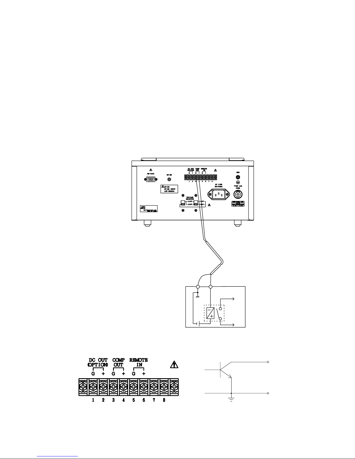
8. REMOT ELY CONTROL LED MEASU REMENT
A measurement can be remotely controlled by shorting the “G” and “+”
terminals of the REMOTE IN o f the External Input/Outpu t terminal bloc k on
the rear of the unit. When the terminals are shorted by a remote switch, a
measurement will start, and when opened the measure ment is ended.
Fig. 8.1.1 shows an example wiring and the signal timing.
Fig. 8.1.2 shows the external input/output terminal block.
■ Signal Timing
REMOTE IN OFF OFF
ON
Fig. 8.1.2
Fig. 8.1.1
www.GlobalTestSupply.com
Find Quality Products Online at: sales@GlobalTestSupply.com
Page 44

34
www.GlobalTestSupply.com
Find Quality Products Online at: sales@GlobalTestSupply.com
Page 45

35
Note 1: When the measuring time is set with the incorporated timer,
the timer has a priority over a remotely controlled switch
actuation.
When the REMOTE IN “G” and “+”
terminals are closed, a
measurement will start. The measurement will automatically end
when the time set with the timer is up.
Note that when the closed “G” and “+” terminals are opened
before the time-up of the timer, the opening of the “G” and “+”
terminals has a priority over the time set with the timer.
Note 2: When the charging time is set with the incorporated timer, the
timer has a priority over a remotely controlled switch
actuation.
When the REMOTE IN “G” and “+” terminals are closed, a
charging will start. The measurement will automatically start
when the charging time set with the timer is up.
Note that when the closed “G” and “+” terminals are opened
before the time-up of the timer, the opening of the “G” and “+”
terminals has a priority over the time set with the timer.
Note 3: When both the charging time and measuring time
are set with
the incorporated timer, the timer has a priority over a re mote
control.
When the REMOTE IN “G” and “+”
terminals are closed, a
charging wil l start.
When the set charging time is up, a measurement
automatically starts. However, note that when the “G” and “+”
terminals are opened before the set measuring time is up ,
the
remote control has a priority over the time set with the timer.
When the set measuring time is up, a measurement
automatically ends. However, note that when the “G” and “+”
terminals are opened before the set measuring time is up , the
remote control has a priority over the time set with the timer.
www.GlobalTestSupply.com
Find Quality Products Online at: sales@GlobalTestSupply.com
Page 46
36
9. INTRODUNTION OF OPTIONS
With the SM-8200 Series super megohmmeters, any of the following options
can be provided as needed. However, note that some of them can be installed
at factory.
9-1 Guar d Tip
1) Applications
1)-1 In a measurement of the insulation resi
stance of a capacitive sample,
the optional guard tip is used as a charging tip.
1)-2 In a measurement of the high insulation resistance, the optional
guard tip is used to guard the sample from the surface current of the
sample support made of insulation materials to obtain more reliable
data.
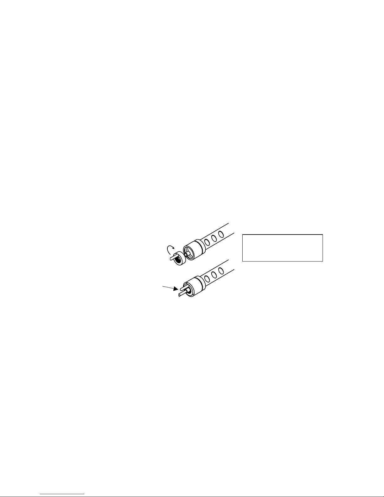
2) Usage
2)-1 Charging Tip
(1) Before connecting the measur ing plug of the red me asuring rod to
the Rx “‑“ terminals, mount the guard tip on the measuring plug as
shown in Fig. 9.1.1.
Fig. 9.1.1
(2) After mounting the guard tip, connect the measuring rod to the Rx
“‑“me asuringterm inals.
(3) Connect the black measuring rod to the sample to measure.
(4) Press the MEASURE switch.
(5) Connect the guard tip of the red measuring rod to the sample to
charge.
(6) When an appropriate period (See Note.) of charging time has passed,
connect the measuring tip of the rod to the sample in place of the
guard tip.
Note 1: When changing the guard tip connection to the measuring
tip connection, a spark may occur, depending upon the
capacitance of the sample.
1)
2)
Turn clockwise
to fit
Sample end of the
red measuring rod
Guard Tip
Measuring Tip
Guard Tip
www.GlobalTestSupply.com
Find Quality Products Online at: sales@GlobalTestSupply.com
Page 47

37
Note 2: There is no technical standards available to specify the
charging time for samples, but a constant time should be
always applied to a specific type of samples, and such a time
should be recorded for later reference.
2)-2 Leakage Guard
(1) Before connecting the measuring rods to the Rx ‑/+measu ring
terminals, mount the guar d tip onto the red measuring rod as shown
in Fig. 9.1.1 on the previous page.
(2) Connect the measuring rods to the Rx ‑/+me asuring terminals.
(3) Connect the samp le as shown in Fig. 9.1.2 bel ow.
Fig. 9.1.2
(4) Press the MEASURE switch to start the measurement.
DANGER
Do not touch the Rx ‑/+ measuring terminals and the connected
sample when the unit is in the MEASURE or CHARGE mode
because they carry the voltage set with the VOLTAGE selector
switch. It is electric shock hazardous.
CAUTION
For safety, unplug the measuring rod from the Rx ‑/+ measuring
terminals before disconnecting the guard tip from the sample.
Sample
Metal Plate
Sample Support
(Insulator)
Black
Measuring Rod
Red
Measuring Rod
Measuring Tip
Guard Tip
-- to be continued --
www.GlobalTestSupply.com
Find Quality Products Online at: sales@GlobalTestSupply.com
Page 48

38
DANGER
Use utmost care when handling a capacitive sample connected
to the Rx ‑/+ measuring terminals because the a capacitive
s ample’s inte rnal impedan ce is low, and a t ouch of the vol tage
applied parts of the sample may discharge the charge of the
sample at a time, giving a strong shock to the operator.
This is especially dangerous when the test voltage is high and
the capacitance of the sample is large.
This suggests, after measurement, to discharge the charge of
the sample without a fail.
9. 2 DC Signal Outputs
Either one of two different types of DC signal outputs can be optionally
installed with the unit at factory. The output can be used to make a
permanent record of measured data by connecting a chart recorder such as
the HIOKI EPR-3000 Series.
One of the outputs provides a linear DC signal directly proportional to the
measured resistance (RP-8000), and the othe r outputs a 1/R DC signal which
is inversely proportional to the measured resistance (RI-8000).
9 .2.1 DC Output, RP-8000 – Directly prop ortional or l inear to resis tance
An insulation resistance can be obtained when the measuring voltage is
divided by the current flowing through the circuit. When the measuring
voltage is constant, if the insulation resistance is doubled, the current
flowing through the circuit is halved. The RP-8000 DC output is designed
to convert the measured insulation resistance into a DC signal directly
proportional to the resistance.
1) Specifications
Output Range: From fu ll scale of the super me gohmmeter to 10 times
full scale
Output Voltage: 1V/full scale, 10 V/10 times full scale
Output Accuracy: Within ±10 % full scale
2) Usage
Measure the insulation resistance of a sample with the method
designed in 6.1 Measuring Method. There is no limitation in the
applications in relation with the provision of the RP-8000 DC output.
Fig. 9.2.1 on the next page illustrates an example connection with
the HIOKI EPR-3000 Series chart recorder.
www.GlobalTestSupply.com
Find Quality Products Online at: sales@GlobalTestSupply.com
Page 49

39
Recorder scale(Linear)
100 V scale
graduation
Fig. 9.2.1
Fig. 9.2.2
Fig. 9.2.2 shows the DC OUT (OPTI ON) “G”/”+” te rminals on the external
inpu t/output te rminal block on the rear of the unit.
A DC measuring instrument like a HIOKI chart recorder can be connected
to these terminals. For permanent data recording, a HIOKI chart recorder
is recommended for better technical follow-up, including a supply of a
variety of recording charts and technical service.
Fig. 9.2.3 shows the chart for the HIOKI EPR-3000 Series chart recorder (0
to 10 V full span) whose measuring range is set to ±5 V, and the –5 V
point is set to the zero (left most) line of the chart.
Fig. 9.2.3
SM‑8200シリーズ
EPR‑3000シリーズ
背面
正面
SM-8200 Series
Super Megohmmeter
HIOKI EPR-3000 Series Chart Recorder
Front
Rear
www.GlobalTestSupply.com
Find Quality Products Online at: sales@GlobalTestSupply.com
Page 50

40
graduation
100 V scale
Voltage
Output
Recorder scale(Linear)
9.2.2 DC O utput, RI-8000 – 1/R or inversely proportional to resistance
In insulation resistance, as described in 9.2.1 DC Output, RP-8000, if the
measuring voltage is constant, the current flowing through the sample is
halved, and the output voltage is also halved when the insulation
resistan ce -- R -- is do ubled. This relation ca n be expressed as “1 /R.”
The RI-8000 provides this type of DC signal output.
1) Specifications
Output Range: Full range of the measuring range of the SM-8200
Series super megohmmeter
Output Voltage: 10 V/full scale, 1 V/10 times full scale
Output Accuracy: Within 10% of displayed value in the range from full
scale to 10 times full scale
2) Usage
Measure the insulation resistance of a sample with the method
designed in 6.1 Measuring Method. There is no limitation in the
applications in relation with the provision of the RP-8000 DC output.
Fig. 9.2.1 on the previous page illustrates an example connection with
the HIOKI EPR-3000 Series chart recorder.
Fig. 9.2.2 on the previous page shows the DC OUT (OPTION) “G”/”+”
terminals on the extern al input/outp ut termina l block on the re ar of
the unit.
A DC measuring instrument like a HIOKI chart recorder whose input
impedance is greater than 10 MΩcan be connected to these terminals.
For permanent data recording, a HIOKI chart recorder is recommended for
better technical follow-up, including a supply of a variety of recording charts
and technical service.
Fig. 9.2.3 shows the chart for the HIOKI EPR-3000 Series chart recorder (0
to 10 V full span) whose measuring range is set to ±5 V, and the –5 V point
is set to the zero (left most) line of the chart.
Fig. 9.2.4
www.GlobalTestSupply.com
Find Quality Products Online at: sales@GlobalTestSupply.com
Page 51

41
10. MAINTENANCE AND MISCELANEOUS
Periodical maintenance, including checking and calibration is required for
the MS-8200 super megohmmeter to pe rform reliable measurements and
prevent a trouble and accident.
If necessary, ask your dealer or Hioki representative
to do such a
s
ervice as periodical checking, calibration and routine maintenance.
10.1 Periodical Checking
To keep your instrument its at best condition, the following checking is
required at monthly periods.
1) Check the Rx measuring term inals and input/output terminal block for
integrity.
As the Rx measuring terminals carry a high voltage (100 V to 1000 V,
maximum, depending upon the model and set-up, visually check the
terminals for any crack, loose connection, etc.
Crack and loose connection will lead a trouble and accident.
2) Clean the pa nels, Rx measur ing termin als, and input/ output termi nal
board with soft cloth.
3) Visually check the LCD display for brightness and clearness.
4) Check the action of the switches and pushbutton switches for smooth
and trouble-free operation.
5) Measure the measuring voltage across the Rx ‑/+ measuring terminals
With a voltmeter. The voltage should be within ±3% of the selected
value.
10.2 Storag e, Transporta tion and Abandon
1) Storage
When the SM-8200 Series unit is shutdown for a long period of time,
unplug the power cord from the AC line outlet, put a dust cover over it,
and store the unit in a place meeting the following conditions.
(1) Free of corrosive gas, dust and vibration
(2) Environment temperature of 5 to 45℃, less than 85% RH
2) Transportation
When the un it is transpo rted, avoid shock and vibr ation.
For long distance transportation, place the unit in a shock absorbing
carton box w ith a HANDLE WITH CARE label to p revent rou gh handling.
3) Abandon
To abandon an old unit, observe the rules of your local government.
www.GlobalTestSupply.com
Find Quality Products Online at: sales@GlobalTestSupply.com
Page 52

42
11. EXTERNAL APPEARANCE
Unit: mm
Approx
Approx.
www.GlobalTestSupply.com
Find Quality Products Online at: sales@GlobalTestSupply.com
Page 53

HIOKI SM-8213, 8215, 8220 SUPER MEGOHMMETER
Instruction Manual
Publication date: November 2006 Edition 1
Edited and published by HIOKI E.E. CORPORATION
Technical Support Section
Printed in Japan SM8213A981-00
• All reasonable care has been taken in the production of this
manual, but if you find any points which are unclear or in error,
please contact your supplier or the International Sales and Marketing Department at HIOKI headquarters.
• In the interests of product development, the contents of this
manual are subject to revision without prior notice.
• Unauthorized reproduction or copying of this manual is
prohibited.
www.GlobalTestSupply.com
Find Quality Products Online at: sales@GlobalTestSupply.com
 Loading...